EP2111826A1 - Dispositif d'introduction avec un dispositif de libération pour la libération d'un objet supporté par un cathéter et dispositif de libération d'un dispositif d'introduction - Google Patents
Dispositif d'introduction avec un dispositif de libération pour la libération d'un objet supporté par un cathéter et dispositif de libération d'un dispositif d'introduction Download PDFInfo
- Publication number
- EP2111826A1 EP2111826A1 EP09156301A EP09156301A EP2111826A1 EP 2111826 A1 EP2111826 A1 EP 2111826A1 EP 09156301 A EP09156301 A EP 09156301A EP 09156301 A EP09156301 A EP 09156301A EP 2111826 A1 EP2111826 A1 EP 2111826A1
- Authority
- EP
- European Patent Office
- Prior art keywords
- catheter
- outer shaft
- release
- winding
- roller
- Prior art date
- Legal status (The legal status is an assumption and is not a legal conclusion. Google has not performed a legal analysis and makes no representation as to the accuracy of the status listed.)
- Granted
Links
- 238000003780 insertion Methods 0.000 title claims abstract description 22
- 230000037431 insertion Effects 0.000 title claims abstract description 22
- 238000004804 winding Methods 0.000 claims abstract description 62
- 238000006073 displacement reaction Methods 0.000 claims abstract description 13
- 210000004204 blood vessel Anatomy 0.000 description 4
- 239000002184 metal Substances 0.000 description 3
- 230000002349 favourable effect Effects 0.000 description 2
- 208000031481 Pathologic Constriction Diseases 0.000 description 1
- 238000002399 angioplasty Methods 0.000 description 1
- 230000010339 dilation Effects 0.000 description 1
- 238000011010 flushing procedure Methods 0.000 description 1
- 238000004519 manufacturing process Methods 0.000 description 1
- 230000013011 mating Effects 0.000 description 1
- 238000000034 method Methods 0.000 description 1
- 238000000926 separation method Methods 0.000 description 1
- 230000006641 stabilisation Effects 0.000 description 1
- 238000011105 stabilization Methods 0.000 description 1
- 208000037804 stenosis Diseases 0.000 description 1
- 230000036262 stenosis Effects 0.000 description 1
- 210000003813 thumb Anatomy 0.000 description 1
Images


Classifications
-
- A—HUMAN NECESSITIES
- A61—MEDICAL OR VETERINARY SCIENCE; HYGIENE
- A61F—FILTERS IMPLANTABLE INTO BLOOD VESSELS; PROSTHESES; DEVICES PROVIDING PATENCY TO, OR PREVENTING COLLAPSING OF, TUBULAR STRUCTURES OF THE BODY, e.g. STENTS; ORTHOPAEDIC, NURSING OR CONTRACEPTIVE DEVICES; FOMENTATION; TREATMENT OR PROTECTION OF EYES OR EARS; BANDAGES, DRESSINGS OR ABSORBENT PADS; FIRST-AID KITS
- A61F2/00—Filters implantable into blood vessels; Prostheses, i.e. artificial substitutes or replacements for parts of the body; Appliances for connecting them with the body; Devices providing patency to, or preventing collapsing of, tubular structures of the body, e.g. stents
- A61F2/95—Instruments specially adapted for placement or removal of stents or stent-grafts
- A61F2/962—Instruments specially adapted for placement or removal of stents or stent-grafts having an outer sleeve
- A61F2/966—Instruments specially adapted for placement or removal of stents or stent-grafts having an outer sleeve with relative longitudinal movement between outer sleeve and prosthesis, e.g. using a push rod
-
- A—HUMAN NECESSITIES
- A61—MEDICAL OR VETERINARY SCIENCE; HYGIENE
- A61F—FILTERS IMPLANTABLE INTO BLOOD VESSELS; PROSTHESES; DEVICES PROVIDING PATENCY TO, OR PREVENTING COLLAPSING OF, TUBULAR STRUCTURES OF THE BODY, e.g. STENTS; ORTHOPAEDIC, NURSING OR CONTRACEPTIVE DEVICES; FOMENTATION; TREATMENT OR PROTECTION OF EYES OR EARS; BANDAGES, DRESSINGS OR ABSORBENT PADS; FIRST-AID KITS
- A61F2/00—Filters implantable into blood vessels; Prostheses, i.e. artificial substitutes or replacements for parts of the body; Appliances for connecting them with the body; Devices providing patency to, or preventing collapsing of, tubular structures of the body, e.g. stents
- A61F2/95—Instruments specially adapted for placement or removal of stents or stent-grafts
- A61F2/962—Instruments specially adapted for placement or removal of stents or stent-grafts having an outer sleeve
- A61F2/97—Instruments specially adapted for placement or removal of stents or stent-grafts having an outer sleeve the outer sleeve being splittable
-
- A—HUMAN NECESSITIES
- A61—MEDICAL OR VETERINARY SCIENCE; HYGIENE
- A61F—FILTERS IMPLANTABLE INTO BLOOD VESSELS; PROSTHESES; DEVICES PROVIDING PATENCY TO, OR PREVENTING COLLAPSING OF, TUBULAR STRUCTURES OF THE BODY, e.g. STENTS; ORTHOPAEDIC, NURSING OR CONTRACEPTIVE DEVICES; FOMENTATION; TREATMENT OR PROTECTION OF EYES OR EARS; BANDAGES, DRESSINGS OR ABSORBENT PADS; FIRST-AID KITS
- A61F2/00—Filters implantable into blood vessels; Prostheses, i.e. artificial substitutes or replacements for parts of the body; Appliances for connecting them with the body; Devices providing patency to, or preventing collapsing of, tubular structures of the body, e.g. stents
- A61F2/95—Instruments specially adapted for placement or removal of stents or stent-grafts
- A61F2/9517—Instruments specially adapted for placement or removal of stents or stent-grafts handle assemblies therefor
Definitions
- the invention relates to an insertion device with a release device for releasing a carried by a catheter object and a release device of an insertion device according to the preambles of the independent claims.
- catheters For the release of articles such as e.g. Stents or in the application of dilation balloons are known to use catheters.
- a field of application relates to e.g. Angioplasty, in which balloon catheters are introduced into blood vessels, inserted into a stenosis and expanded there to eliminate the constriction of the blood vessel.
- a small diameter guidewire protrudes beyond the balloon catheter at the distal end.
- an intravascular prosthetic introducer wherein a catheter engages a tread at its proximal end to facilitate relative displacement between an inner and an outer sheath of the catheter.
- a distal end article such as a stent
- the outer sheath is pulled toward the proximal end. The movement can be uniform by pulling the outer shell into the running device.
- the invention has for its object to provide an improved introducer with a release device for a subject to be released as well as an improved release device of an introducer, which allows for easier and ergonomic handling.
- the invention relates to an insertion device with a release device for releasing an article, in particular a support body, which is supported by a catheter, wherein the catheter has at least one outer shaft, which is relatively displaceable against the object for its release.
- the catheter has, at its proximal end, a winding device which winds a proximal section of the outer shaft in order to produce a relative displacement of the outer shaft.
- the spooling causes the outer shaft to slide away from the distal end of the catheter to the proximal end.
- the sliding movement can be controlled and precise.
- the spooling allows for a compact design of the catheter having a length independent of the length of the object to be released, which may for example be a stent.
- the winding device can relieve the user and at least partially take over the propulsion force for the retraction of the outer shaft during the release of the object. A release can be very controlled and accurate.
- the displacement of the outer shaft can be continuous and uniform. It is also conceivable that a variable displacement speed can be realized manually or automatically, to retire the outer shaft slowly and at the beginning of the release more quickly and towards the end of the release the outer shaft.
- the release device can preferably have a cutting device with which the section of the outer shaft moving toward the proximal end of the catheter can be cut open.
- the cutting device may have at least one cutting edge, which cuts open the outer shaft in the axial direction. By cutting open the outer shaft, the free end of the outer shaft can be taken in the winding device and wound up.
- the catheter can be formed independently of the length of the support body. In the production of catheters for different articles to be released, such as stents, inexpensive identical parts can be used.
- the release device can form a grip part of the catheter. This allows a particularly ergonomic handling of the catheter.
- the release device may form a T-body as an end piece of the catheter.
- the winding device may preferably comprise a roller which is arranged on one side on the catheter. A cut can be produced in the outer shaft and the cut-up skirt surface can be wound up by the winding device.
- the winding device may comprise at least two rollers, preferably arranged symmetrically on the catheter.
- at least two cuts can be produced and the cut-open portion of the outer shaft can be divided into separate surface areas which can each be grasped and wound separately from the winding device. This facilitates the winding, which can be done with less effort.
- the invention is based on a release device of an insertion device for releasing an object, in particular a support body, which is carried by a catheter at its distal end, wherein the catheter has at least one outer shaft which is relatively displaceable against the object for its release.
- a winding device that winds to form a relative displacement of the outer shaft a proximal portion of the outer shaft.
- the spooling causes the outer shaft to slide away from the distal end of the catheter to the proximal end.
- the sliding movement can be controlled and precise.
- a release of the article can be very controlled and accurate, since the small dimension of the handling part advantageously allows optimal handling.
- the displacement of the outer shaft can be continuous and uniform. It is also conceivable that a variable displacement speed can be realized manually or automatically in order to withdraw the outer shaft slowly and, for example, at the beginning of the release for a more precise positioning, and to retract the outer shaft more quickly towards the end of the release.
- the winding device can be conveniently connected to a conventional catheter.
- a cutting device can be coupled with the winding device, with which the section of the outer shaft moving toward the proximal end of the catheter can be cut open, when the outer shaft moves to release the object at the distal end of the catheter to the proximal end.
- At least one roller may be provided in the winding device, to which the outer shaft can be wound at least in regions.
- the outer shaft can be moved at a constant speed of revolution at a variable speed.
- An improved handling results when the at least one roller can be locked by a lock. This allows a defined start of the release and a good control of the movement of the outer shaft, which can also be interrupted controlled.
- the winding device for winding can be conveniently coupled to a spring element so that by the spring force winding and / or movement of the External support can be supported. This allows a particularly simple and controlled handling of the winding device.
- the winding device for winding the outer shaft can be driven manually, z. B. with a crank element.
- the winding device may alternatively or in addition to winding the outer shaft comprise an electric drive.
- the winding of the outer shaft can be done without the use of force of the user.
- the winding device may have an actuating element which releases the at least one roller for carrying out a rotational movement in a first position and blocks the at least one roller in a further position.
- an actuating element which releases the at least one roller for carrying out a rotational movement in a first position and blocks the at least one roller in a further position.
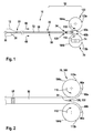
- Fig. 1 shows a first preferred embodiment of the invention with a preferred first introducer 10 with a preferred release means 70 for releasing an article 12, in particular a support body carried at a distal end 22 of a catheter 20, the catheter 20 having at least one outer shaft 50, which is relatively displaceable against the article 12 for release in a draw direction 68.
- the catheter 20 has at its proximal end 24 a winding device 100 which winds to form the relative displacement of the outer shaft 50 a proximal portion 52 of the outer shaft 50.
- the proximal portion 52 of the outer shaft 50 corresponds to the length of the article 12, e.g. may be a self-expanding stent.
- Proximal and distal refer to the position of the user, the proximal end 24 is adjacent to the user while the distal end 22 is remote from the user.
- the outer shaft 50 is arranged around an inner shaft 28, wherein at the distal end 22 of the catheter 20, a tip 30 for guiding the catheter 20 via an insertion wire (Guide Wire) is provided in a conventional manner, wherein the article 12 surrounds the inner shaft 28 and for insertion into, for example, a blood vessel within the outer shaft 50.
- a tip 30 for guiding the catheter 20 via an insertion wire Guide Wire
- the winding device 100 in this exemplary embodiment comprises two rollers 104a, 104b which are arranged symmetrically with respect to the catheter 20 or outer shaft 50 and which can be driven by a drive (not shown), e.g. a crank or an electric motor.
- a drive e.g. a crank or an electric motor.
- the release device 70 comprises, in addition to the winding device 100, a cutting device 120 with at least one cutting edge 122, with which the section 52 of the outer shaft 50 moved toward the proximal end 24 of the catheter 20 can be cut along the longitudinal extension 72 of the outer shaft 50.
- a symmetrical separation of the outer shaft 50 into two parts 60a, 60b is expedient.
- the outer shaft 50 may be cut open at the proximal end of the catheter 20 and its ends secured to the rollers 104a, 104b.
- the rollers 104a, 104b are rotated, the parts 60a, 60b are laid down on a lateral surface 113a (roller 104a) and 113b (roller 104b) of the rollers 104a, 104b and fastened with the ends 66a, 66b, as in the detail of FIGS Fig. 2 can be seen more clearly.
- the rollers 104a, 104b are rotated in opposite directions of rotation 110, 112, the roller 104a e.g. in the counterclockwise direction and the roller 104b in a clockwise direction.
- the rotation can be done with a drive 74, e.g. a manually operable crank, or even electrically (not shown).
- the drive 74 is actuated on the roller 104b and set in rotation, this can be achieved by a favorable embodiment of the winding device 100 (FIG. Fig. 4a, 4b ) the other roller 104a are moved with.
- a toothed wheel 108a, 108b is arranged on each roller 104a, 104b at one end.
- the gears 108a, 108b mesh with each other, so that the movement of a roller 104b, for example, the other role, eg 104a, entrains and allows symmetrical winding ( Fig. 4a, 4b ).
- FIG. 12 shows a variant of the invention in which a plurality of cuts are not made in the outer shaft 50 but only a one-sided cut 54 is made from a proximal free end 66 of the outer shaft 50 to a stop 58 along the longitudinal extent 72 of the catheter 20.
- the winding device (not shown) then preferably has only a single role for winding the outer shaft 50, as in the embodiment in Fig. 7a, 7b is explained in more detail.
- Fig. 5 shows a preferred release device 70 with two rollers 104a, 104b in a housing 86 in plan view
- Fig. 6 shows an end body 80 of the catheter 20 in side view, on which the housing 86 with the release device 70 is arranged (housing and winding device in the side view in FIG Fig. 6 not shown) can be.
- the end body 80 may also be integrated into the housing 86 of the release device 70
- the rollers 104a, 104b are symmetrical to each other and rotate in opposite directions.
- the rollers 104a, 104b may be fixed or released with a detent 118 disposed on one of the rollers 104b.
- the inner shaft 28 of the catheter 20 (FIG. Fig. 1 ) can eg by means of a metal shaft 88 ( Fig. 6 ; Fig. 8a, 8b ) are fixed in the housing 86.
- a kink guard 26 is attached to the catheter 20, which encases the catheter 20.
- a port 82 e.g. in the form of a so-called Luer lock, serves for the usual flushing of a space between inner shaft 28 and outer shaft 50, and arranged at the free end port 84, which may also be formed as a Luer lock, serves for introducing a guide wire (Guide Wire) and the Rinse this area.
- a guide wire Guide Wire
- two symmetrically arranged blades 122 are arranged on a lug 124 of the end body 80, which cut the outer shaft 50 from the inside when retracted. It would also be conceivable to arrange the outer shaft 50 with external cutting edges (not shown) longitudinally.
- Distal and proximal seals 80 and 96 are respectively disposed on the end body 80 to seal the space between the inner shaft 28 and the outer shaft 50, and the metal shaft 88 and the end body 80 and the outer shaft 50, respectively.
- the already partially slotted outer shaft 50 is attached to the outer surfaces 113a, 113b of the rollers 104a, 104b to be wound on them, as in FIGS Fig. 1 and 2 was hinted at.
- the outer shaft 50 is wound up and thus automatically retracted to the proximal end 24 of the catheter 20.
- the article 12 (FIG. Fig. 1 ), such as a self-expanding stent, released.
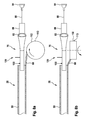
- Fig. 7a, 7b schematically illustrate further preferred embodiments of an insertion device 10 according to the invention with a release device 70, which comprises a winding device 100, which has only one roller 102 and comprises a one-sided cutting device, as shown in FIG Fig. 3 is shown schematically.
- the roller 102 is arranged on one side of the catheter 20.
- the release device 70 is integrated into an end body 80 of the catheter 20 and forms a handle portion of the catheter 20 with a grip portion 94 which the user can hold in his hand.
- the roller 102 can be rotated either clockwise or counterclockwise with the user only allowed to rotate in one direction and the opposite direction locked.
- the catheter 20 is externally provided with a kink guard 26, protrudes into the end body 80, and may also be secured to the end body 80 with a metal stem as described above.
- Fig. 7a shows an embodiment in which the roller 102 of the winding device 100 is arranged upright, so that the roller 102 with its circular area is parallel to the catheter 20.
- Fig. 7b an alternative embodiment is shown, in which the catheter 20 is arranged tangentially to the roller 102.
- the existing cutting device is not shown explicitly.
- the roller 102 can be fixed or released, which is indicated by a double arrow.
- the roller 102 is disposed distal to the handle portion 94 of the end body 80.
- the roller 102 rotate, for example, with the thumb, so that a one-handed operation of the release device 70 and the winding device 100 of the insertion device 10 is possible. Stopping the slicing may be accomplished with a stop member 58 (FIG. Fig. 1, 2 . 3 ), or by allowing only a limited number of revolutions of roll 102.
- Fig. 8a and 8b show a further preferred embodiment of the invention with a designed as T-body end body 80, wherein the roller 102 of the winding device 100 tangentially ( Fig. 8a ) or parallel next to the catheter 20 and the end body 80 (FIG. Fig. 8b ) is arranged.
- the rollers 102, 104a, 104b in the above-described embodiments of the winding device 100 may have a cylindrical lateral surface 113 or may also have a tapered shape, as in FIG Fig. 9 is shown.
- the roller 102, 104a, 104b has a larger diameter of the lateral surface 113 than at its opposite axial end 116. This results in that the parts 60, 60a, 60b of the outer shaft 50 at a constant rotational speed of the roller 102, 104a, 104b are wound at different speeds, depending on the axial height at which the parts 60, 60a, 60b are deposited.
- the Figures 10a and 10b show a detail of an advantageous winding device 100, in which the roller 102, 104a, 104b can be mechanically or electrically rotated with a triggering mechanism 130.
- the triggering mechanism extends along a central axis 140 of the roller 102, 104a, 104b.
- An actuating element 132 can be moved downward against a spring force of a spring element 134 designed as an axial spring, for example.
- a counter element 138 is moved out of a brake 136 and the axle 140 is thus released.
- the brake 136 may include brake shoes engaged by the mating member 138 when the roller 102, 104a, 104b is blocked.
- the axle 140 is coupled to a spring element 106 designed as a torsion spring, which can set the axle 140 and thus the roller 102, 104a, 104b in a rotational movement when the counter element 138 is decoupled from the brake 136.
- a spring element 106 designed as a torsion spring, which can set the axle 140 and thus the roller 102, 104a, 104b in a rotational movement when the counter element 138 is decoupled from the brake 136.
- the spring element 106 may also be provided an electric drive.
- the coil 102, 104a, 104b can be operated by the push of a button and offers the possibility of realizing different winding speeds. Stopping the slicing can be achieved, for example, by allowing only a limited number of revolutions of the rollers 102, 104a, 104b and / or limited movement of the spring element 106.
- the slicing and winding of the outer shaft 50 allows for the provision of a short handling portion of the catheter 20. This advantageously results in easier handling and shortened displacement of the catheter 20 over the guidewire (guide wire).
- the simplification of the release process in particular via a simple button operation of the release device, allows a more accurate and homogeneous positioning of the article, e.g. a stent in the blood vessel.
Landscapes
- Health & Medical Sciences (AREA)
- Engineering & Computer Science (AREA)
- Biomedical Technology (AREA)
- Cardiology (AREA)
- Oral & Maxillofacial Surgery (AREA)
- Transplantation (AREA)
- Heart & Thoracic Surgery (AREA)
- Vascular Medicine (AREA)
- Life Sciences & Earth Sciences (AREA)
- Animal Behavior & Ethology (AREA)
- General Health & Medical Sciences (AREA)
- Public Health (AREA)
- Veterinary Medicine (AREA)
- Media Introduction/Drainage Providing Device (AREA)
Applications Claiming Priority (1)
| Application Number | Priority Date | Filing Date | Title |
|---|---|---|---|
| DE102008021060A DE102008021060A1 (de) | 2008-04-26 | 2008-04-26 | Einführvorrichtung mit einer Freisetzeinrichtung zur Freisetzung eines von einem Katheter getragenen Gegenstandes sowie Freisetzeinrichtung einer Einführvorrichtung |
Publications (2)
| Publication Number | Publication Date |
|---|---|
| EP2111826A1 true EP2111826A1 (fr) | 2009-10-28 |
| EP2111826B1 EP2111826B1 (fr) | 2012-11-28 |
Family
ID=40845886
Family Applications (1)
| Application Number | Title | Priority Date | Filing Date |
|---|---|---|---|
| EP09156301A Active EP2111826B1 (fr) | 2008-04-26 | 2009-03-26 | Dispositif d'introduction avec un dispositif de libération pour la libération d'un objet supporté par un cathéter et dispositif de libération d'un dispositif d'introduction |
Country Status (3)
| Country | Link |
|---|---|
| US (1) | US8778006B2 (fr) |
| EP (1) | EP2111826B1 (fr) |
| DE (1) | DE102008021060A1 (fr) |
Cited By (6)
| Publication number | Priority date | Publication date | Assignee | Title |
|---|---|---|---|---|
| WO2010120670A1 (fr) * | 2009-04-15 | 2010-10-21 | Cook Incorporated | Appareil d'introduction |
| EP2910221A1 (fr) * | 2014-02-25 | 2015-08-26 | Biotronik AG | Dispositif de dégagement pour libérer un implant médical d'un cathéter ainsi que cathéter avec dispositif de dégagement |
| EP3400914A1 (fr) | 2017-05-08 | 2018-11-14 | Biotronik AG | Poignée pour un cathéter et cathéter correspondant |
| WO2019053507A1 (fr) * | 2017-09-13 | 2019-03-21 | CARDINAL HEALTH SWITZERLAND 515 GmbH | Cathéter de pose de stent à commande à molette fine et à manivelle à main rapide |
| WO2021061182A1 (fr) * | 2019-09-25 | 2021-04-01 | Aquedeon Medical, Inc. | Greffons vasculaire et aortique et outils de déploiement |
| US12029639B2 (en) | 2018-07-03 | 2024-07-09 | Aquedeon Medical, Inc. | Vascular and aortic grafts and deployment tool |
Families Citing this family (21)
| Publication number | Priority date | Publication date | Assignee | Title |
|---|---|---|---|---|
| WO2010120671A1 (fr) * | 2009-04-15 | 2010-10-21 | Cook Incorporated | Système et poignée à déploiement réversible |
| EP2623151A4 (fr) * | 2010-09-28 | 2014-04-16 | Terumo Corp | Gaine d'introducteur, dispositif de placement pour un instrument de traitement de vaisseau sanguin et procédé de raccourcissement de gaine d'introducteur |
| US8657866B2 (en) * | 2010-12-22 | 2014-02-25 | Cook Medical Technologies Llc | Emergency vascular repair prosthesis deployment system |
| GB2488107B (en) * | 2011-02-11 | 2013-03-06 | Cook Medical Technologies Llc | Drive assembly for facilitating deployment of an implantable medical device |
| GB2488531B (en) * | 2011-02-18 | 2013-04-10 | Cook Medical Technologies Llc | Introducer and deployment handle for splittable sheath |
| US20120259355A1 (en) * | 2011-04-08 | 2012-10-11 | Kyphon Sarl | Retractable inflatable bone tamp |
| US10213329B2 (en) | 2011-08-12 | 2019-02-26 | W. L. Gore & Associates, Inc. | Evertable sheath devices, systems, and methods |
| US9131959B2 (en) * | 2011-08-22 | 2015-09-15 | Cook Medical Technologies Llc | Splittable dilator delivery system |
| US9849015B2 (en) | 2012-12-28 | 2017-12-26 | Cook Medical Technologies Llc | Endoluminal prosthesis introducer |
| US9763819B1 (en) | 2013-03-05 | 2017-09-19 | W. L. Gore & Associates, Inc. | Tapered sleeve |
| US9974676B2 (en) | 2013-08-09 | 2018-05-22 | Cook Medical Technologies Llc | Wire collection device with geared advantage |
| US9974677B2 (en) | 2013-08-20 | 2018-05-22 | Cook Medical Technologies Llc | Wire collection device for stent delivery system |
| US9907641B2 (en) | 2014-01-10 | 2018-03-06 | W. L. Gore & Associates, Inc. | Implantable intraluminal device |
| US10966850B2 (en) * | 2014-03-06 | 2021-04-06 | W. L. Gore & Associates, Inc. | Implantable medical device constraint and deployment apparatus |
| US9974678B2 (en) | 2014-03-10 | 2018-05-22 | Cook Medical Technologies Llc | Wire collection device with varying collection diameter |
| WO2016094068A1 (fr) * | 2014-12-09 | 2016-06-16 | Cook Medical Technologies Llc | Poignée à deux broches |
| US20180325585A1 (en) * | 2017-05-15 | 2018-11-15 | Biosense Webster (Israel) Ltd. | Networked thermistors |
| WO2019075069A1 (fr) | 2017-10-11 | 2019-04-18 | W. L. Gore & Associates, Inc. | Appareil de déploiement et de contrainte de dispositifs médicaux implantables |
| US10441449B1 (en) | 2018-05-30 | 2019-10-15 | Vesper Medical, Inc. | Rotary handle stent delivery system and method |
| US10449073B1 (en) | 2018-09-18 | 2019-10-22 | Vesper Medical, Inc. | Rotary handle stent delivery system and method |
| US11219541B2 (en) | 2020-05-21 | 2022-01-11 | Vesper Medical, Inc. | Wheel lock for thumbwheel actuated device |
Citations (7)
| Publication number | Priority date | Publication date | Assignee | Title |
|---|---|---|---|---|
| EP0747021A2 (fr) | 1995-06-07 | 1996-12-11 | Cook Incorporated | Dispositif d'introduction d'un stent |
| US6533811B1 (en) * | 1993-07-08 | 2003-03-18 | Medtronic, Inc. | Internal graft prosthesis and delivery system |
| EP1447058A1 (fr) | 1998-09-30 | 2004-08-18 | Bard Peripheral Vascular, Inc. | Mécanisme de mise en place d'extenseur implantable |
| US6866669B2 (en) | 2001-10-12 | 2005-03-15 | Cordis Corporation | Locking handle deployment mechanism for medical device and method |
| DE60011355T2 (de) | 1999-08-24 | 2005-07-14 | Novatech Sa | Anbringungssystem für eine intravaskuläre Prothese |
| EP1844739A1 (fr) * | 2006-04-13 | 2007-10-17 | Medtronic Vascular, Inc. | Poignée courte pour une endoprothèse longue |
| WO2009091603A1 (fr) * | 2008-01-15 | 2009-07-23 | Gore Enterprise Holdings, Inc. | Fourreau expansible plaqué |
Family Cites Families (13)
| Publication number | Priority date | Publication date | Assignee | Title |
|---|---|---|---|---|
| US5346498A (en) * | 1991-11-06 | 1994-09-13 | Imagyn Medical, Inc. | Controller for manipulation of instruments within a catheter |
| WO1994015549A1 (fr) * | 1992-12-30 | 1994-07-21 | Schneider (Usa) Inc. | Appareil de deploiement d'extenseurs implantables |
| DE19936207A1 (de) * | 1999-08-02 | 2001-02-15 | Angiomed Ag | Katheter und Einführbesteck mit Trenneinrichtung |
| US6660031B2 (en) * | 2001-04-11 | 2003-12-09 | Scimed Life Systems, Inc. | Multi-length delivery system |
| US6599296B1 (en) * | 2001-07-27 | 2003-07-29 | Advanced Cardiovascular Systems, Inc. | Ratcheting handle for intraluminal catheter systems |
| US6673101B1 (en) * | 2002-10-09 | 2004-01-06 | Endovascular Technologies, Inc. | Apparatus and method for deploying self-expanding stents |
| US7967829B2 (en) * | 2003-10-09 | 2011-06-28 | Boston Scientific Scimed, Inc. | Medical device delivery system |
| US20050256562A1 (en) * | 2004-05-14 | 2005-11-17 | Boston Scientific Scimed, Inc. | Stent delivery handle and assembly formed therewith |
| JP4439437B2 (ja) * | 2005-06-15 | 2010-03-24 | グローブライド株式会社 | 魚釣用電動リール |
| DE102006004123A1 (de) * | 2006-01-25 | 2007-08-02 | Jotec Gmbh | Einführsystem für Stents mit Zug-Druck-Kinematik |
| US20070219617A1 (en) * | 2006-03-17 | 2007-09-20 | Sean Saint | Handle for Long Self Expanding Stent |
| US8029481B2 (en) * | 2006-10-17 | 2011-10-04 | Matthew Dickson Reavill | Apparatus and method of inserting an infusing catheter and determining catheter depth without a guidewire or direct contact with the catheter |
| US7976574B2 (en) * | 2008-08-08 | 2011-07-12 | Advanced Cardiovascular Systems, Inc. | Delivery system with variable delivery rate for deploying a medical device |
-
2008
- 2008-04-26 DE DE102008021060A patent/DE102008021060A1/de not_active Withdrawn
-
2009
- 2009-03-26 EP EP09156301A patent/EP2111826B1/fr active Active
- 2009-04-27 US US12/430,191 patent/US8778006B2/en active Active
Patent Citations (7)
| Publication number | Priority date | Publication date | Assignee | Title |
|---|---|---|---|---|
| US6533811B1 (en) * | 1993-07-08 | 2003-03-18 | Medtronic, Inc. | Internal graft prosthesis and delivery system |
| EP0747021A2 (fr) | 1995-06-07 | 1996-12-11 | Cook Incorporated | Dispositif d'introduction d'un stent |
| EP1447058A1 (fr) | 1998-09-30 | 2004-08-18 | Bard Peripheral Vascular, Inc. | Mécanisme de mise en place d'extenseur implantable |
| DE60011355T2 (de) | 1999-08-24 | 2005-07-14 | Novatech Sa | Anbringungssystem für eine intravaskuläre Prothese |
| US6866669B2 (en) | 2001-10-12 | 2005-03-15 | Cordis Corporation | Locking handle deployment mechanism for medical device and method |
| EP1844739A1 (fr) * | 2006-04-13 | 2007-10-17 | Medtronic Vascular, Inc. | Poignée courte pour une endoprothèse longue |
| WO2009091603A1 (fr) * | 2008-01-15 | 2009-07-23 | Gore Enterprise Holdings, Inc. | Fourreau expansible plaqué |
Cited By (16)
| Publication number | Priority date | Publication date | Assignee | Title |
|---|---|---|---|---|
| WO2010120670A1 (fr) * | 2009-04-15 | 2010-10-21 | Cook Incorporated | Appareil d'introduction |
| US9326874B2 (en) | 2009-04-15 | 2016-05-03 | Cook Medical Technologies Llc | Introducer apparatus |
| EP2910221A1 (fr) * | 2014-02-25 | 2015-08-26 | Biotronik AG | Dispositif de dégagement pour libérer un implant médical d'un cathéter ainsi que cathéter avec dispositif de dégagement |
| US10299949B2 (en) | 2014-02-25 | 2019-05-28 | Biotronik Ag | Release device for releasing a medical implant from a catheter, and catheter |
| EP3400914A1 (fr) | 2017-05-08 | 2018-11-14 | Biotronik AG | Poignée pour un cathéter et cathéter correspondant |
| WO2018206205A1 (fr) | 2017-05-08 | 2018-11-15 | Biotronik Ag | Poignée pour cathéter, et cathéter correspondant |
| CN110536661A (zh) * | 2017-05-08 | 2019-12-03 | 百多力股份公司 | 导管的手柄和相应的导管 |
| CN110536661B (zh) * | 2017-05-08 | 2022-05-03 | 百多力股份公司 | 导管的手柄和相应的导管 |
| WO2019053507A1 (fr) * | 2017-09-13 | 2019-03-21 | CARDINAL HEALTH SWITZERLAND 515 GmbH | Cathéter de pose de stent à commande à molette fine et à manivelle à main rapide |
| US11241324B2 (en) | 2017-09-13 | 2022-02-08 | CARDINAL HEALTH SWITZERLAND 515 GmbH | Stent delivery catheter with fine thumbwheel control and fast crank handle |
| IL270234B1 (en) * | 2017-09-13 | 2023-06-01 | Cardinal Health 515 Gmbh | A support that includes a transfer catheter with fine control and a quick turning handle |
| US12029639B2 (en) | 2018-07-03 | 2024-07-09 | Aquedeon Medical, Inc. | Vascular and aortic grafts and deployment tool |
| US11712330B2 (en) | 2019-07-03 | 2023-08-01 | Aquedeon Medical, Inc. | Vascular and aortic grafts and deployment tools |
| US11864977B2 (en) | 2019-07-03 | 2024-01-09 | Aquedeon Medical, Inc. | Vascular and aortic grafts and deployment tools |
| US11944530B2 (en) | 2019-07-03 | 2024-04-02 | Aquedeon Medical, Inc. | Vascular and aortic grafts and deployment tools |
| WO2021061182A1 (fr) * | 2019-09-25 | 2021-04-01 | Aquedeon Medical, Inc. | Greffons vasculaire et aortique et outils de déploiement |
Also Published As
| Publication number | Publication date |
|---|---|
| EP2111826B1 (fr) | 2012-11-28 |
| DE102008021060A1 (de) | 2009-10-29 |
| US8778006B2 (en) | 2014-07-15 |
| US20090270969A1 (en) | 2009-10-29 |
Similar Documents
| Publication | Publication Date | Title |
|---|---|---|
| EP2111826B1 (fr) | Dispositif d'introduction avec un dispositif de libération pour la libération d'un objet supporté par un cathéter et dispositif de libération d'un dispositif d'introduction | |
| EP2496152B1 (fr) | Dispositif pour recanalisation d'un organe tubulaire, kit comprenant un tel dispositif et méthode pour sa fabrication | |
| EP1976466B1 (fr) | Systeme d'insertion de protheses intravasculaires a cinematique de traction-compression | |
| DE3889333T2 (de) | Katheter für ballon-angioplastie. | |
| EP1964532B1 (fr) | Dispositif destiné à libérer un stent autoextensible dans un vaisseau corporel | |
| DE69431262T2 (de) | Expandierbare vorrichtung zum entfernen von verschlüssen in gefässen | |
| DE60207065T2 (de) | Vorrichtung zum Einbringen eines selbstexpandierbaren Stents | |
| DE2800362C3 (de) | Endoskop mit steuerbar beweglicher Führungsröhre für ein Instrument | |
| DE69824431T2 (de) | Medizinisches fangkörbchen | |
| EP0442137B1 (fr) | Dispositif d'athérectomie | |
| DE3714560C2 (fr) | ||
| EP2667804B1 (fr) | Canule de sécurité suprapubienne | |
| EP0536610A1 (fr) | Dispositif pour la dilatation d'une sténose | |
| EP0884063A1 (fr) | Système de cathéter | |
| DE29717110U1 (de) | Vorrichtung zum Einführen eines Stents, eines Drainagerohrs o.dgl. in Hohlorgane | |
| DE3114896A1 (de) | "drehmechanismus zur einfuehrung einer fetalelektrode" | |
| DE202020106210U1 (de) | Kathetervorrichtung | |
| DE102014222600A1 (de) | Medizinisches Fangdrahtinstrument | |
| EP2910221B1 (fr) | Dispositif de dégagement pour libérer un implant médical d'un cathéter ainsi que cathéter avec dispositif de dégagement | |
| WO2011076390A1 (fr) | Dispositif pour placer un implant médical et agencement comprenant un tel dispositif | |
| WO2011107532A1 (fr) | Instrument médical | |
| WO2009077203A2 (fr) | Dispositif de traitement endovasculaire servant en particulier à extraire des concrétions de lumières corporelles | |
| EP4426238A1 (fr) | Unité portative pour l'introduction et la libération d'un implant | |
| DE102021132089A1 (de) | Handeinheit zum Zuführen und Freigeben eines Implantats | |
| DE19750332C2 (de) | Endoskopisch geführte Drainlegevorrichtung |
Legal Events
| Date | Code | Title | Description |
|---|---|---|---|
| PUAI | Public reference made under article 153(3) epc to a published international application that has entered the european phase |
Free format text: ORIGINAL CODE: 0009012 |
|
| AK | Designated contracting states |
Kind code of ref document: A1 Designated state(s): AT BE BG CH CY CZ DE DK EE ES FI FR GB GR HR HU IE IS IT LI LT LU LV MC MK MT NL NO PL PT RO SE SI SK TR |
|
| AX | Request for extension of the european patent |
Extension state: AL BA RS |
|
| 17P | Request for examination filed |
Effective date: 20100330 |
|
| 17Q | First examination report despatched |
Effective date: 20100507 |
|
| AKX | Designation fees paid |
Designated state(s): CH DE FR GB IE LI |
|
| GRAP | Despatch of communication of intention to grant a patent |
Free format text: ORIGINAL CODE: EPIDOSNIGR1 |
|
| GRAS | Grant fee paid |
Free format text: ORIGINAL CODE: EPIDOSNIGR3 |
|
| GRAA | (expected) grant |
Free format text: ORIGINAL CODE: 0009210 |
|
| AK | Designated contracting states |
Kind code of ref document: B1 Designated state(s): CH DE FR GB IE LI |
|
| REG | Reference to a national code |
Ref country code: GB Ref legal event code: FG4D Free format text: NOT ENGLISH |
|
| REG | Reference to a national code |
Ref country code: CH Ref legal event code: EP |
|
| REG | Reference to a national code |
Ref country code: IE Ref legal event code: FG4D Free format text: LANGUAGE OF EP DOCUMENT: GERMAN |
|
| REG | Reference to a national code |
Ref country code: DE Ref legal event code: R096 Ref document number: 502009005487 Country of ref document: DE Effective date: 20130124 |
|
| PLBE | No opposition filed within time limit |
Free format text: ORIGINAL CODE: 0009261 |
|
| STAA | Information on the status of an ep patent application or granted ep patent |
Free format text: STATUS: NO OPPOSITION FILED WITHIN TIME LIMIT |
|
| 26N | No opposition filed |
Effective date: 20130829 |
|
| REG | Reference to a national code |
Ref country code: DE Ref legal event code: R097 Ref document number: 502009005487 Country of ref document: DE Effective date: 20130829 |
|
| REG | Reference to a national code |
Ref country code: DE Ref legal event code: R082 Ref document number: 502009005487 Country of ref document: DE Representative=s name: RANDOLL, SOEREN, DIPL.-CHEM. UNIV. DR. RER. NA, DE |
|
| REG | Reference to a national code |
Ref country code: FR Ref legal event code: PLFP Year of fee payment: 8 |
|
| REG | Reference to a national code |
Ref country code: FR Ref legal event code: PLFP Year of fee payment: 9 |
|
| REG | Reference to a national code |
Ref country code: FR Ref legal event code: PLFP Year of fee payment: 10 |
|
| REG | Reference to a national code |
Ref country code: DE Ref legal event code: R082 Ref document number: 502009005487 Country of ref document: DE Ref country code: DE Ref legal event code: R081 Ref document number: 502009005487 Country of ref document: DE Owner name: BIOTRONIK AG, CH Free format text: FORMER OWNER: BIOTRONIK VI PATENT AG, BAAR, CH |
|
| REG | Reference to a national code |
Ref country code: GB Ref legal event code: 732E Free format text: REGISTERED BETWEEN 20180719 AND 20180725 |
|
| REG | Reference to a national code |
Ref country code: FR Ref legal event code: TP Owner name: BIOTRONIK AG, CH Effective date: 20180907 |
|
| PGFP | Annual fee paid to national office [announced via postgrant information from national office to epo] |
Ref country code: IE Payment date: 20220322 Year of fee payment: 14 |
|
| P01 | Opt-out of the competence of the unified patent court (upc) registered |
Effective date: 20230605 |
|
| REG | Reference to a national code |
Ref country code: IE Ref legal event code: MM4A |
|
| PG25 | Lapsed in a contracting state [announced via postgrant information from national office to epo] |
Ref country code: IE Free format text: LAPSE BECAUSE OF NON-PAYMENT OF DUE FEES Effective date: 20230326 |
|
| PGFP | Annual fee paid to national office [announced via postgrant information from national office to epo] |
Ref country code: DE Payment date: 20240321 Year of fee payment: 16 Ref country code: GB Payment date: 20240322 Year of fee payment: 16 |
|
| PGFP | Annual fee paid to national office [announced via postgrant information from national office to epo] |
Ref country code: FR Payment date: 20240320 Year of fee payment: 16 |
|
| PGFP | Annual fee paid to national office [announced via postgrant information from national office to epo] |
Ref country code: CH Payment date: 20240401 Year of fee payment: 16 |