EP2108924A2 - Positionsbestimmungsvorrichtung und Verfahren - Google Patents
Positionsbestimmungsvorrichtung und Verfahren Download PDFInfo
- Publication number
- EP2108924A2 EP2108924A2 EP09001838A EP09001838A EP2108924A2 EP 2108924 A2 EP2108924 A2 EP 2108924A2 EP 09001838 A EP09001838 A EP 09001838A EP 09001838 A EP09001838 A EP 09001838A EP 2108924 A2 EP2108924 A2 EP 2108924A2
- Authority
- EP
- European Patent Office
- Prior art keywords
- wave signal
- amplitude
- sine wave
- cosine
- cosine wave
- Prior art date
- Legal status (The legal status is an assumption and is not a legal conclusion. Google has not performed a legal analysis and makes no representation as to the accuracy of the status listed.)
- Granted
Links
- 238000000034 method Methods 0.000 title claims description 9
- 230000005284 excitation Effects 0.000 claims description 12
- 238000001514 detection method Methods 0.000 claims description 4
- 238000010586 diagram Methods 0.000 description 1
Images

Classifications
-
- G—PHYSICS
- G01—MEASURING; TESTING
- G01D—MEASURING NOT SPECIALLY ADAPTED FOR A SPECIFIC VARIABLE; ARRANGEMENTS FOR MEASURING TWO OR MORE VARIABLES NOT COVERED IN A SINGLE OTHER SUBCLASS; TARIFF METERING APPARATUS; MEASURING OR TESTING NOT OTHERWISE PROVIDED FOR
- G01D5/00—Mechanical means for transferring the output of a sensing member; Means for converting the output of a sensing member to another variable where the form or nature of the sensing member does not constrain the means for converting; Transducers not specially adapted for a specific variable
- G01D5/12—Mechanical means for transferring the output of a sensing member; Means for converting the output of a sensing member to another variable where the form or nature of the sensing member does not constrain the means for converting; Transducers not specially adapted for a specific variable using electric or magnetic means
- G01D5/244—Mechanical means for transferring the output of a sensing member; Means for converting the output of a sensing member to another variable where the form or nature of the sensing member does not constrain the means for converting; Transducers not specially adapted for a specific variable using electric or magnetic means influencing characteristics of pulses or pulse trains; generating pulses or pulse trains
- G01D5/24471—Error correction
- G01D5/2448—Correction of gain, threshold, offset or phase control
-
- G—PHYSICS
- G01—MEASURING; TESTING
- G01B—MEASURING LENGTH, THICKNESS OR SIMILAR LINEAR DIMENSIONS; MEASURING ANGLES; MEASURING AREAS; MEASURING IRREGULARITIES OF SURFACES OR CONTOURS
- G01B15/00—Measuring arrangements characterised by the use of electromagnetic waves or particle radiation, e.g. by the use of microwaves, X-rays, gamma rays or electrons
-
- G—PHYSICS
- G01—MEASURING; TESTING
- G01B—MEASURING LENGTH, THICKNESS OR SIMILAR LINEAR DIMENSIONS; MEASURING ANGLES; MEASURING AREAS; MEASURING IRREGULARITIES OF SURFACES OR CONTOURS
- G01B21/00—Measuring arrangements or details thereof, where the measuring technique is not covered by the other groups of this subclass, unspecified or not relevant
-
- G—PHYSICS
- G01—MEASURING; TESTING
- G01B—MEASURING LENGTH, THICKNESS OR SIMILAR LINEAR DIMENSIONS; MEASURING ANGLES; MEASURING AREAS; MEASURING IRREGULARITIES OF SURFACES OR CONTOURS
- G01B7/00—Measuring arrangements characterised by the use of electric or magnetic techniques
-
- H—ELECTRICITY
- H03—ELECTRONIC CIRCUITRY
- H03L—AUTOMATIC CONTROL, STARTING, SYNCHRONISATION OR STABILISATION OF GENERATORS OF ELECTRONIC OSCILLATIONS OR PULSES
- H03L7/00—Automatic control of frequency or phase; Synchronisation
Definitions
- the present invention relates to a position detecting device and a position detecting method that use a resolver. More particularly, the present invention relates a position detecting device and a position detecting method that detects a position of an object by amplifying a sine wave signal and a cosine wave signal of a resolver provided in the object.
- Some conventional position detecting device uses a resolver, an amplifier circuit and a microcomputer as disclosed in US 2003/0111974 A1 ( JP 2003-166803 A ).
- the sine phase signal and the cosine phase signal produced by the resolver are amplified by the amplifier circuit in the interface circuit and applied to the microcomputer.
- the microcomputer calculates a difference between gains of the amplified sine phase signal and the amplified cosine phase signal produced by the I/F circuit, and corrects the outputs of the amplifier circuit in accordance with the calculated difference.
- the difference in the detected angle caused by the difference of the gains in the outputs of the amplifier circuit is reduced.
- the amplified sine phase signal and the amplified cosine phase signal are amplified, the positive amplitude and the negative amplitude of each of the amplified sine phase signal and the amplified cosine phase signal sometimes vary from each other. Therefore, the amplified sine phase signal and the amplified cosine phase signal are corrected based on the difference of gains of the sine phase signal and the cosine phase signal.
- the difference between the positive amplitude and the negative amplitude of the sine phase signal or the cosine phase signal is not considered. As a result, it is not possible to reduce any error in the detection of the angular position caused by any difference between the positive amplitude and the negative amplitude of the amplified sine phase signal or the amplified cosine phase signal.
- a first sine wave signal and a first cosine wave signal produced by a resolver provided in an object such as a motor is amplified to a second sine wave signal and a second cosine wave signal, respectively, and the position of the object is determined in accordance with the second sine wave signal and the second cosine wave signal.
- At least one of the second sine wave signal and the second cosine wave signal is corrected so that all of positive amplitudes and negative amplitudes of the second sine wave signal and the second cosine wave signal become equal one another and used to determine the position of the object.
- the second sine wave signal is corrected based on a comparison of a positive amplitude and a negative amplitude of the second sine wave signal to produce a third sine wave signal
- the second cosine wave signal is corrected based on a comparison of a positive amplitude and a negative amplitude of the second cosine wave signal to produce a third cosine wave signal
- at least one of the third sine wave signal and the third cosine wave signal is corrected based on a comparison of an amplitude of the third sine wave signal and an amplitude of the third cosine wave signal to produce a fourth sine wave signal and a fourth cosine wave signal.
- the position of the object is determined by using the fourth sine wave signal and the fourth cosine wave signal.
- a position detecting device 1 includes a resolver 10 provided in a motor (not shown) M and an electronic signal processing unit 11.
- the resolver 10 is configured to produce a first sine wave signal and a first cosine wave signal in the analog voltage form, which varies with a rotation angular position of a rotor shaft of the motor M, when an analog excitation signal is applied thereto. Specifically, when the exciting signal Ksin ⁇ t is applied, the resolver 10 produces a first sine wave signal Kcos ⁇ sin ⁇ t and a first cosine wave signal Ksin ⁇ cos ⁇ t, which vary with the rotation angle ⁇ .
- the signal processing unit 11 is configured to produce the excitation signal for the resolver 10 and calculates the position (rotation angle ⁇ ) of the motor M based on the first sine wave signal and the first cosine wave signal produced by the resolver 10.
- the signal processing unit 11 includes an excitation signal generator circuit (excitation circuit) 110, an analog sine wave signal amplifier circuit (sine amplifier) 111, an analog cosine wave signal amplifier circuit (cosine amplifier) 112 and a microcomputer (signal processor) 113.
- the excitation circuit 110 is connected to the microcomputer 113 at the input terminal thereof and the resolver 10 at the output terminal thereof. It produces the excitation signal in response to a command from the microcomputer 113 and applies it to the resolver 10.
- the sine amplifier 111 is connected to the resolver 10 at an input terminal thereof and the microcomputer 113 at the output terminal thereof. It amplifies the first sine wave signal produced from the resolver 10 and applies the amplified first sine wave signal to the microcomputer 113 as a second sine wave signal in the analog voltage form.
- the cosine amplifier 112 is connected to the resolver 10 at the input terminal thereofr and the microcomputer 113 at an output terminal thereof. It amplifies the first cosine wave signal produced from the resolver 10 and applies the amplified first cosine wave signal to the microcomputer 113 as a second cosine wave signal in the analog voltage form.
- the microcomputer 113 is configured and programmed to control the excitation circuit 110 so that the excitation circuit 110 responsively produces the excitation signal. It is further configured and programmed to correct the second sine wave signal and the second cosine wave signal received from the sine amplifier 111 and the cosine amplifier 112, respectively, and calculates the position (rotation angle) of the motor M based on the corrected signals.
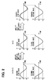
- the operation of the position detecting device 1, particularly the operation of the signal processing unit 11, is described next with further reference to FIG. 2 .
- the signal processing unit 11 starts its operation, when electric power is supplied thereto. With the excitation signal applied from the excitation circuit 110, the resolver 10 produces the first sine wave signal and the first cosine wave signal varying with the motor rotation angle ⁇ .
- the amplifiers 111 and 112 amplify these signals and apply the second sine wave signal and the second cosine wave signal to the microcomputer 113.
- the amplitudes of the first sine wave signal and the first cosine wave signal are equal to each other.
- the amplitudes sometimes become different between the second sine wave signal and the second cosine wave signal, if the sine amplifier 111 and the cosine amplifier 112 have operation characteristic variations.
- the positive amplitude (voltage level in the positive polarity side) and the negative amplitude (voltage level in the negative polarity side) also sometimes become different.
- the microcomputer 113 therefore measures the amplitudes and calculates a ratio between the positive amplitude and the negative amplitude of the second sine wave signal as a comparison result, and corrects at least one of the positive amplitude and the negative amplitude of the second sine wave signal in accordance with the calculated ratio to equalize the positive amplitude and the negative amplitude.
- a third sine wave signal having the same positive and negative amplitudes is determined.
- the third sine wave signal may be determined by amplifying one of the positive amplitude or the negative amplitude of the second sine wave signal by a predetermined gain.
- the microcomputer measures the amplitudes and calculates a ratio between the positive amplitude and the negative amplitude of the second cosine wave signal as a comparison result, and corrects at least one of the positive amplitude and the negative amplitude of the second cosine wave signal in accordance with the calculated ratio to equalize the positive amplitude and the negative amplitude.
- a third cosine wave signal having the same positive and negative amplitudes is determined.
- the third cosine wave signal may be determined by amplifying one of the positive amplitude or the negative amplitude of the second cosine wave signal by a predetermined gain.
- the microcomputer 113 calculates a ratio of the amplitude of the third sine wave signal and the amplitude of the third cosine wave signal, and corrects at least one of the amplitudes of the third sine wave signal and the third cosine wave signal in accordance with the calculated ratio to equalize the amplitudes of the sine wave signal and the cosine wave signal.
- a fourth sine wave signal and a fourth cosine wave having the same amplitude are determined.
- the fourth sine wave signal and the fourth cosine wave signal may be determined by amplifying only one of the third sine wave signal and the third cosine wave signal by a predetermined gain and maintaining the other of the two third wave signals. It is also possible to amplify both the third sine wave signal and the third cosine wave signal by different gains to determine the fourth sine wave signal and the fourth cosine wave signal having the same amplitudes.
- the microcomputer 113 determines the rotation angle of the motor M based on the fourth sine wave signal and the fourth cosine wave signal in the known manner. This determined rotation angle may be used to control the operation of the motor M in the known manner.
- the third sine wave signal having the same amplitude B is determined.
- the microcomputer 113 further measures the positive amplitude and the negative amplitude of the second cosine wave signal and compares the measured amplitudes. If the amplitudes C of the second cosine wave signal are equal to each other and greater than the amplitudes A and B of the second sine wave signal, the second cosine wave signal is used as it is as the third cosine wave signal.
- the microcomputer 113 thus determines the third sine wave signal, which has the same amplitude B in both positive signal part and negative signal part, and the third cosine wave signal, which has the same amplitude C in both positive signal part and the negative signal part.
- the third cosine signal having the amplitudes C in both positive and negative signal parts are used as it is as the fourth cosine wave signal.
- the fourth sine wave signal and the fourth cosine wave signal having the same amplitudes are determined.
- the microcomputer 113 then calculates the rotation angle of the motor M based on the two fourth signals having the same amplitude C.
- the rotation position can be determined accurately even if the sine wave signal and the cosine wave signal of the resolver 10 are amplified by the amplifiers 111 and 112 having different operation characteristics.
- each of the amplified (second) wave signals are corrected to have the same amplitudes in both positive amplitude and negative amplitude by using the ratio of its amplitudes in the positive polarity and the negative polarity, the variation in the positive amplitude and the negative amplitude can be suppressed surely.
- the final (fourth) sine wave signal and the final (fourth) cosine wave signal are determined to have the same amplitude therebetween by correcting either one of the preceding (third) wave signals in accordance with the ratio of magnitudes of the preceding wave signals, the variation in the magnitudes between the sine wave signal and the cosine wave signal can be suppressed surely.
- the present embodiment may be modified as follows.
- the second sine wave signal may be corrected by correcting the positive signal part by the ratio A/B so that the positive amplitude becomes the amplitude A, in place of correcting the negative signal part by the ratio B/A.
- the second sine wave signal may be corrected by correcting both the positive signal part and the negative signal part by respective gains different from each other as long as the resulting positive amplitude and the negative amplitude become equal.
- the third cosine wave signal having the amplitude C may be corrected to become equal to the amplitude B of the third sine wave signal, in place of correcting the third sine wave signal to have the amplitude C.
- both the third sine wave signal and the third cosine wave signal may be corrected to have the same amplitude different from any of the amplitudes B and C.
Landscapes
- Physics & Mathematics (AREA)
- General Physics & Mathematics (AREA)
- Electromagnetism (AREA)
- Transmission And Conversion Of Sensor Element Output (AREA)
Applications Claiming Priority (1)
| Application Number | Priority Date | Filing Date | Title |
|---|---|---|---|
| JP2008099258A JP4524705B2 (ja) | 2008-04-07 | 2008-04-07 | 位置検出装置及び位置検出補正方法 |
Publications (3)
| Publication Number | Publication Date |
|---|---|
| EP2108924A2 true EP2108924A2 (de) | 2009-10-14 |
| EP2108924A3 EP2108924A3 (de) | 2013-03-27 |
| EP2108924B1 EP2108924B1 (de) | 2016-02-10 |
Family
ID=41004892
Family Applications (1)
| Application Number | Title | Priority Date | Filing Date |
|---|---|---|---|
| EP09001838.3A Ceased EP2108924B1 (de) | 2008-04-07 | 2009-02-10 | Positionsbestimmungsvorrichtung und Verfahren |
Country Status (4)
| Country | Link |
|---|---|
| US (1) | US7873487B2 (de) |
| EP (1) | EP2108924B1 (de) |
| JP (1) | JP4524705B2 (de) |
| KR (1) | KR101235413B1 (de) |
Families Citing this family (6)
| Publication number | Priority date | Publication date | Assignee | Title |
|---|---|---|---|---|
| CN101865699B (zh) * | 2009-04-14 | 2012-11-21 | 鸿富锦精密工业(深圳)有限公司 | 弦波解码装置及其解码方法 |
| JP5895442B2 (ja) * | 2010-12-01 | 2016-03-30 | 株式会社デンソー | 角度検出装置の異常判断装置 |
| US8680849B2 (en) | 2011-03-01 | 2014-03-25 | Hamilton Sundstrand Corporation | Spring loaded gear driven resolver |
| KR101664567B1 (ko) | 2014-10-20 | 2016-10-10 | 현대자동차주식회사 | 레졸버의 위치 정보 오차를 보상하기 위한 장치 및 방법 |
| DE102015213924A1 (de) * | 2015-07-23 | 2017-01-26 | Volkswagen Aktiengesellschaft | Fahrzeug, Lenksystem, eine Resolveranordnung sowie Verfahren zur Verarbeitung von Ausgangssignalen eines Resolvers |
| JP7251751B2 (ja) * | 2017-11-07 | 2023-04-04 | 株式会社松尾製作所 | 電気角取得システム、電気角取得方法、電気角取得プログラム、電気角取得特性測定システム、電気角取得特性測定方法および電気角取得特性測定プログラム |
Citations (1)
| Publication number | Priority date | Publication date | Assignee | Title |
|---|---|---|---|---|
| JP2003166803A (ja) | 2001-12-04 | 2003-06-13 | Toyoda Mach Works Ltd | 位置検出器の補正方法、及び、電気式動力舵取装置 |
Family Cites Families (4)
| Publication number | Priority date | Publication date | Assignee | Title |
|---|---|---|---|---|
| JP2515891B2 (ja) * | 1989-09-20 | 1996-07-10 | 株式会社日立製作所 | 角度センサ及びトルクセンサ、そのセンサの出力に応じて制御される電動パワ―ステアリング装置 |
| JP2947124B2 (ja) * | 1995-05-31 | 1999-09-13 | 日本電気株式会社 | アンテナ角度誤差補正装置 |
| JP2004045286A (ja) * | 2002-07-12 | 2004-02-12 | Denso Corp | レゾルバ補正方法 |
| JP2005208028A (ja) * | 2003-12-22 | 2005-08-04 | Minebea Co Ltd | バリアブルリラクタンスレゾルバ用角度演算方法とそのための角度演算装置 |
-
2008
- 2008-04-07 JP JP2008099258A patent/JP4524705B2/ja not_active Expired - Fee Related
-
2009
- 2009-02-10 EP EP09001838.3A patent/EP2108924B1/de not_active Ceased
- 2009-02-17 US US12/372,165 patent/US7873487B2/en not_active Expired - Fee Related
- 2009-04-06 KR KR1020090029185A patent/KR101235413B1/ko not_active Expired - Fee Related
Patent Citations (2)
| Publication number | Priority date | Publication date | Assignee | Title |
|---|---|---|---|---|
| JP2003166803A (ja) | 2001-12-04 | 2003-06-13 | Toyoda Mach Works Ltd | 位置検出器の補正方法、及び、電気式動力舵取装置 |
| US20030111974A1 (en) | 2001-12-04 | 2003-06-19 | Toyoda Machine Works, Ltd. | Position detector correction method and electrically-powered steering apparatus |
Also Published As
| Publication number | Publication date |
|---|---|
| EP2108924A3 (de) | 2013-03-27 |
| KR20090106996A (ko) | 2009-10-12 |
| US20090254295A1 (en) | 2009-10-08 |
| KR101235413B1 (ko) | 2013-02-20 |
| EP2108924B1 (de) | 2016-02-10 |
| US7873487B2 (en) | 2011-01-18 |
| JP2009250790A (ja) | 2009-10-29 |
| JP4524705B2 (ja) | 2010-08-18 |
Similar Documents
| Publication | Publication Date | Title |
|---|---|---|
| US7343254B2 (en) | Resolver digital converter | |
| EP2108924B1 (de) | Positionsbestimmungsvorrichtung und Verfahren | |
| US8514110B2 (en) | Resolver digital converter | |
| US6925401B2 (en) | Method and apparatus for correcting resolver output | |
| JP2020018168A (ja) | モータモジュールおよびモータ認証方法 | |
| EP2559971A1 (de) | Rotationswinkelerkennungsvorrichtung | |
| WO2011024730A1 (ja) | 回転角検出装置 | |
| JP5011824B2 (ja) | 異常判定装置 | |
| US20150276373A1 (en) | Resolver excitation circuit | |
| US20150009517A1 (en) | Rotation-angle detection device and method, and image processing apparatus | |
| JP5176208B2 (ja) | 回転角度検出方法および回転角度センサ | |
| JP5331980B2 (ja) | 回転角度センサ及び回転角度算出方法 | |
| CN107561398B (zh) | 正余弦编码器断线故障检测方法及装置 | |
| JP2017118708A (ja) | 回転角センサ取り付け角度測定装置および回転角センサ取り付け角度測定方法 | |
| JP2007057316A (ja) | レゾルバインターフェース装置 | |
| US10374541B2 (en) | Motor control system and method for detecting abnormality in resolver/digital converter | |
| JP2801124B2 (ja) | トルクセンサの零点誤差の補正方法 | |
| US10312836B2 (en) | Disconnection detection apparatus of sinusoidal wave signal | |
| JP2803966B2 (ja) | トルクセンサの零点誤差の補正方法 | |
| US20180231611A1 (en) | Detection of current sensor malfunction | |
| JP6112832B2 (ja) | 角度補正装置及び回転角センサ | |
| US20070273372A1 (en) | Method of Determining Angles | |
| JP4725109B2 (ja) | ブラシレスモータ | |
| JP5429575B2 (ja) | レゾルバ信号処理装置 | |
| KR20180132191A (ko) | 센싱 시스템 및 방법 |
Legal Events
| Date | Code | Title | Description |
|---|---|---|---|
| PUAI | Public reference made under article 153(3) epc to a published international application that has entered the european phase |
Free format text: ORIGINAL CODE: 0009012 |
|
| AK | Designated contracting states |
Kind code of ref document: A2 Designated state(s): AT BE BG CH CY CZ DE DK EE ES FI FR GB GR HR HU IE IS IT LI LT LU LV MC MK MT NL NO PL PT RO SE SI SK TR |
|
| AX | Request for extension of the european patent |
Extension state: AL BA RS |
|
| PUAL | Search report despatched |
Free format text: ORIGINAL CODE: 0009013 |
|
| AK | Designated contracting states |
Kind code of ref document: A3 Designated state(s): AT BE BG CH CY CZ DE DK EE ES FI FR GB GR HR HU IE IS IT LI LT LU LV MC MK MT NL NO PL PT RO SE SI SK TR |
|
| AX | Request for extension of the european patent |
Extension state: AL BA RS |
|
| RIC1 | Information provided on ipc code assigned before grant |
Ipc: G01D 5/244 20060101AFI20130221BHEP |
|
| 17P | Request for examination filed |
Effective date: 20130514 |
|
| AKX | Designation fees paid |
Designated state(s): DE FR |
|
| GRAP | Despatch of communication of intention to grant a patent |
Free format text: ORIGINAL CODE: EPIDOSNIGR1 |
|
| INTG | Intention to grant announced |
Effective date: 20150821 |
|
| GRAS | Grant fee paid |
Free format text: ORIGINAL CODE: EPIDOSNIGR3 |
|
| GRAA | (expected) grant |
Free format text: ORIGINAL CODE: 0009210 |
|
| AK | Designated contracting states |
Kind code of ref document: B1 Designated state(s): DE FR |
|
| REG | Reference to a national code |
Ref country code: FR Ref legal event code: PLFP Year of fee payment: 8 |
|
| REG | Reference to a national code |
Ref country code: DE Ref legal event code: R096 Ref document number: 602009036137 Country of ref document: DE |
|
| REG | Reference to a national code |
Ref country code: DE Ref legal event code: R084 Ref document number: 602009036137 Country of ref document: DE |
|
| REG | Reference to a national code |
Ref country code: DE Ref legal event code: R097 Ref document number: 602009036137 Country of ref document: DE |
|
| PLBE | No opposition filed within time limit |
Free format text: ORIGINAL CODE: 0009261 |
|
| STAA | Information on the status of an ep patent application or granted ep patent |
Free format text: STATUS: NO OPPOSITION FILED WITHIN TIME LIMIT |
|
| 26N | No opposition filed |
Effective date: 20161111 |
|
| REG | Reference to a national code |
Ref country code: FR Ref legal event code: PLFP Year of fee payment: 9 |
|
| REG | Reference to a national code |
Ref country code: FR Ref legal event code: PLFP Year of fee payment: 10 |
|
| PGFP | Annual fee paid to national office [announced via postgrant information from national office to epo] |
Ref country code: DE Payment date: 20180219 Year of fee payment: 10 |
|
| PGFP | Annual fee paid to national office [announced via postgrant information from national office to epo] |
Ref country code: FR Payment date: 20180223 Year of fee payment: 10 |
|
| REG | Reference to a national code |
Ref country code: DE Ref legal event code: R119 Ref document number: 602009036137 Country of ref document: DE |
|
| PG25 | Lapsed in a contracting state [announced via postgrant information from national office to epo] |
Ref country code: DE Free format text: LAPSE BECAUSE OF NON-PAYMENT OF DUE FEES Effective date: 20190903 |
|
| PG25 | Lapsed in a contracting state [announced via postgrant information from national office to epo] |
Ref country code: FR Free format text: LAPSE BECAUSE OF NON-PAYMENT OF DUE FEES Effective date: 20190228 |