EP2107979B1 - Wischarm - Google Patents
Wischarm Download PDFInfo
- Publication number
- EP2107979B1 EP2107979B1 EP07822075A EP07822075A EP2107979B1 EP 2107979 B1 EP2107979 B1 EP 2107979B1 EP 07822075 A EP07822075 A EP 07822075A EP 07822075 A EP07822075 A EP 07822075A EP 2107979 B1 EP2107979 B1 EP 2107979B1
- Authority
- EP
- European Patent Office
- Prior art keywords
- bolt
- wiper arm
- fastening part
- spring
- sheet
- Prior art date
- Legal status (The legal status is an assumption and is not a legal conclusion. Google has not performed a legal analysis and makes no representation as to the accuracy of the status listed.)
- Active
Links
- 239000002184 metal Substances 0.000 claims description 13
- 239000000725 suspension Substances 0.000 description 7
- 238000005452 bending Methods 0.000 description 3
- 238000004519 manufacturing process Methods 0.000 description 2
- 230000006835 compression Effects 0.000 description 1
- 238000007906 compression Methods 0.000 description 1
- 239000000463 material Substances 0.000 description 1
- 238000004080 punching Methods 0.000 description 1
Images

Classifications
-
- B—PERFORMING OPERATIONS; TRANSPORTING
- B60—VEHICLES IN GENERAL
- B60S—SERVICING, CLEANING, REPAIRING, SUPPORTING, LIFTING, OR MANOEUVRING OF VEHICLES, NOT OTHERWISE PROVIDED FOR
- B60S1/00—Cleaning of vehicles
- B60S1/02—Cleaning windscreens, windows or optical devices
- B60S1/04—Wipers or the like, e.g. scrapers
- B60S1/32—Wipers or the like, e.g. scrapers characterised by constructional features of wiper blade arms or blades
- B60S1/34—Wiper arms; Mountings therefor
- B60S1/3463—Means to press blade onto screen
- B60S1/3465—Means to press blade onto screen with coil springs
- B60S1/3468—Mountings therefor
-
- B—PERFORMING OPERATIONS; TRANSPORTING
- B60—VEHICLES IN GENERAL
- B60S—SERVICING, CLEANING, REPAIRING, SUPPORTING, LIFTING, OR MANOEUVRING OF VEHICLES, NOT OTHERWISE PROVIDED FOR
- B60S1/00—Cleaning of vehicles
- B60S1/02—Cleaning windscreens, windows or optical devices
- B60S1/04—Wipers or the like, e.g. scrapers
- B60S1/32—Wipers or the like, e.g. scrapers characterised by constructional features of wiper blade arms or blades
- B60S1/34—Wiper arms; Mountings therefor
- B60S1/3425—Constructional aspects of the arm
- B60S1/3436—Mounting heads
- B60S1/3438—Manufacturing details thereof
Definitions
- the invention relates to a wiper arm of a windshield wiper device with a fastening part.
- the publication EP 1 167 136 A2 shows a wiper arm attachment part comprising side walls.
- the side walls have bent over portions which comprise a groove through which a bolt can be inserted. On the bolt then a spring can be attached.
- the publication FR 2 724 897 shows a spring suspension in a hinge part of a wiper arm.
- the publication DE 100 10 174 A1 shows a Gußbefest onlysteil for a wiper arm.
- the invention therefore has the object to improve a wiper arm of the type mentioned in that future can be dispensed with the spring suspension made of sheet metal.
- the invention solves this problem with a wiper arm with the features of claim 1.
- At least one of the tabs may be bent toward the interior of the sheet-metal fastening part. This reduces the length of the bolt. The shorter the length of the bolt, the smaller is its deflection, which can occur as a result of the spring force. Since the deflection of the bolt reduces the bearing force of the wiper arm, the shortest possible bolt ensures a high contact force. Furthermore, the bolt is not visible from the outside by the at least one bent tab. ff
- the one tab may have a through hole and the other tab may have an U-shaped or L-shaped recess.
- the U-shaped or L-shaped recess allows rapid assembly of the bolt. It also gives the bolt a secure hold during operation.
- the support of the bolt is additionally secured.
- the clamping of the bolt avoids undesirable twisting of the bolt. Since disturbing squeaking noises can be caused by the rotation of the bolt during operation, they are avoided by the clamping.
- the bolt may be provided with a rough surface.
- the surface may have corrugations and / or knurls.
- the bolt may have a head. Consequently, the bolt can be inserted through the provided in one of the tabs through hole, the head prevents slipping of the bolt through the through hole.
- the tabs in the connection area in which they are connected to the sheet-metal fastening part, the highest possible width. This avoids that the tabs bent over to the interior of the sheet-metal fastening part can be bent open by the spring force. To save material, the width of the tabs may decrease towards their free end.
- the stud with a diameter of 3 millimeters has shown good results in terms of deflection.
- the bolt has a diameter of 3 millimeters on a relatively small circumference, so that it causes no disturbing squeaking noises during a possible rotational movement.
- the bolt may be hardened.
- the invention also relates to a windshield wiper device, in particular for a motor vehicle, which according to the invention has the wiper arm according to one of claims 1 to 10.
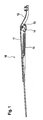
- Fig. 1 shows a wiper arm 10 with a hinge part 11 and a fixing part 12.
- the hinge part 11 is hinged to the fixing part 12, so that a wiper blade not shown in detail here is pivotally mounted on the wiper arm 10. In this way, the wiper blade can be folded away from a vehicle window and folded onto the vehicle window.
- a C-bracket 14 On a bolt 13, a C-bracket 14 is mounted, in which a spring 15 is mounted, which in turn is also mounted on the hinge part 11.
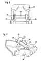
- Fig. 2 shows a fastening part 20 with two tabs 21 and 22 and a bolt 23.
- the tabs 21 and 22 are bent to the interior of the fastening part 20 out.
- the bolt 23 has a relatively short length. Due to the relatively short length of the bolt 23, the deflection is reduced and consequently ensures a maximum contact force of the wiper arm 10.
- the tab 21 has a through hole 30 (see Fig. 3 ), through which the bolt 23 is inserted.
- the bolt is provided with a head 24 (see also Fig. 2 ), which prevents the bolt 23 from slipping through the through hole 30.
- the tab 22 has an L-shaped recess 40 (see Fig. 4 ), in which the bolt 23 is mounted.
- the spring not shown here pushes the pin 23 in the L-shaped recess 40 so that the pin 23 has a secure hold during operation.
- Fig. 5 shows a fixing member 50 with tabs 51 and 52, each having U-shaped recesses 53 and 54.
- a bolt 55 is inserted in the recesses 53 and 54.
- the spring also not shown here, pushes the pin 55 in operation into the U-shaped recesses 53 and 54.
- the pin 55 can be clamped by bending legs 56 and 58 into the recesses 53 and 54. By the clamping of the bolt 55, this is in the recesses 53 and 54 secured.
- the clamping avoids that the bolt 55 can rotate and thereby generates squeaking noises.
- the bolt 55 is provided with a corrugation, which also helps prevent twisting of the bolt 55.
- the bolts 13, 23 and 55 are hardened to prevent wear by the spring arranged thereon.
Landscapes
- Engineering & Computer Science (AREA)
- Mechanical Engineering (AREA)
- Connection Of Plates (AREA)
- Springs (AREA)
- Cleaning Implements For Floors, Carpets, Furniture, Walls, And The Like (AREA)
- Vehicle Cleaning, Maintenance, Repair, Refitting, And Outriggers (AREA)
Description
- Die Erfindung betrifft einen Wischarm einer Scheibenwischvorrichtung mit einem Befestigungsteil.
- Nach dem eine Entwicklung von Gussbefestigungsteilen hin zu Blechbefestigungsteilen stattgefunden hat, hat man im Zuge dieser Entwicklung auch eine eine Feder aufnehmende Federeinhängung aus Blech bei den Blechbefestigungsteilen vorgesehen. Bei der aus Blech hergestellten Federeinhängung kann es jedoch vorkommen, dass sich die Feder im Laufe der Zeit in das Blech der Federeinhängung eingräbt. Daraus resultiert ein Verlust der Auflagekraft des Wischarms, da die Federlänge durch die in das Blech eingegrabene Feder kürzer wird. Ausserdem führen Riefen und Grate, die durch die Herstellung der Federeinhängung verursacht werden, an der Oberfläche der Federeinhängung zu einer unerwünschten Geräuschentwicklung während des Betriebes des Wischarms .
- Die Offenlegungsschrift
EP 1 167 136 A2 zeigt ein Wischarmbefestigungsteil umfassend Seitenwände. Die Seitenwände weisen umgebogene Abschnitt auf, welche eine Nut umfassen, durch welche ein Bolzen gesteckt werden kann. An dem Bolzen kann dann eine Feder befestigt werden. - Die Patentschrift
US 3,427,676 zeigt eine Druckfederanordnung für einen Wischarm. - Die Offenlegungsschrift
FR 2 724 897 - Die Offenlegungsschrift
DE 100 10 174 A1 zeigt ein Gußbefestigungsteil für einen Wischerarm. - Die Erfindung hat deshalb die Aufgabe, einen Wischarm der eingangs genannten Art dahingehend zu verbessern, dass zukünftig auf die aus Blech gefertigte Federeinhängung verzichtet werden kann.
- Die Erfindung löst die gestellte Aufgabe mit einem Wischarm mit dem Merkmalen des Anspruchs 1.
- Mindestens eine der Laschen kann zum Inneren des Blechbefestigungsteiles hin umgebogen sein. Dadurch reduziert sich die Länge des Bolzens. Je kürzer die Länge des Bolzens ist, umso geringer ist auch seine Durchbiegung, die infolge der Federkraft auftreten kann. Da die Durchbiegung des Bolzens die Auflagekraft des Wischarms reduziert, gewährleistet ein möglichst kurzer Bolzen eine hohe Auflagekraft. Ferner ist der Bolzen durch die mindestens eine umgebogene Lasche von außen nicht sichtbar. Ff
- In einer bevorzugten Ausführungsform kann die eine Lasche ein Durchgangsloch und die andere Lasche eine Ü-förmige oder L-förmige Ausnehmung aufweisen. Die U-förmige oder L-förmige Ausnehmung ermöglicht eine rasche Montage des Bolzens. Außerdem gibt sie dem Bolzen einen sicheren Halt während des Betriebes.
- Diese Vorteile kommen noch besser zum Tragen, wenn beide Laschen eine U-förmige Ausnehmung aufweisen.
- Erfindungsgemäß ist der in den U-förmigen Ausnehmungen angeordnete Bolzen geklemmt. Somit wird der Halt des Bolzens zusätzlich gesichert. Außerdem vermeidet die Klemmung des Bolzens ein unerwünschtes Verdrehen des Bolzens. Da durch das Verdrehen des Bolzens im Betrieb störende Quietschgeräusche hervorgerufen werden können, werden diese durch die Klemmung vermieden.
- Um das Verdrehen des Bolzens zuverlässig zu verhindern, kann der Bolzen mit einer rauen Oberfläche versehen sein. Vorzugsweise kann die Oberfläche Riffelungen und/oder Rändelungen aufweisen.
- In einer bevorzugten Ausführungsform kann der Bolzen einen Kopf aufweisen. Folglich kann der Bolzen durch das in einer der Laschen vorgesehene Durchgangsloch gesteckt werden, wobei der Kopf ein Durchrutschen des Bolzens durch das Durchgangsloch verhindert.
- Sinnvollerweise weisen die Laschen im Anbindungsbereich, in dem sie am Blechbefestigungsteil angebunden sind, eine möglichst hohe Breite auf. Dadurch wird vermieden, dass die zum Inneren des Blechbefestigungsteiles hin umgebogenen Laschen durch die Federkraft aufgebogen werden können. Um Material zu sparen, kann die Breite der Laschen zu ihrem freien Ende hin abnehmen.
- In der Praxis hat der Bolzen mit einem Durchmesser von 3 Millimetern gute Ergebnisse bezüglich der Durchbiegung gezeigt. Außerdem weist der Bolzen bei einem Durchmesser von 3 Millimetern einen relativ geringen Umfang auf, so dass er bei einer eventuellen Rotationsbewegung keine störenden Quietschgeräusche verursacht.
- Um die Gefahr eines Verschleißes des Bolzens zu reduzieren, kann der Bolzen gehärtet sein.
- Die Erfindung betrifft auch eine Scheibenwischvorrichtung, insbesondere für ein Kraftfahrzeug, welches erfindungsgemäß den Wischarm nach einem der Ansprüche 1 bis 10 aufweist.
- Außerdem betrifft die Erfindung ein Verfahren zur Herstellung des Blechbefestigungsteiles des Wischarms nach einem der Ansprüche 1 bis 10, das durch folgende Schritte gekennzeichnet ist:
- Ausstanzen des Blechbefestigungsteiles zusammen mit den Laschen und dem Durchgangsloch und/oder den Ausnehmungen,
- Ziehen des Randes,
- Montieren des Bolzens in das Blechbefestigungsteil und Umbiegen der Laschen oder
- Umbiegen der Laschen und Montieren des Bolzens.
- Nachfolgend werden verschiedene Ausführungsbeispiele des erfindungsgemäßen Wischarms anhand der beiliegenden Zeichnungen näher erläutert.
- Im Einzelnen zeigen:
- Fig. 1
- einen Längsschnitt durch einen Wischarm;
- Fig. 2
- eine Vorderansicht auf eine erste Ausführungsform eines Befestigungsteiles;
- Fig. 3
- eine perspektivische Ansicht von unten auf das Befestigungsteil aus
Fig. 2 ; - Fig. 4
- eine weitere perspektivische Ansicht von unten auf das Befestigungsteil aus
Fig. 2 ; - Fig. 5
- eine perspektivische Ansicht von unten auf eine zweite Ausführungsform des Befestigungsteiles.
-
Fig. 1 zeigt einen Wischarm 10 mit einem Gelenkteil 11 und einem Befestigungsteil 12. Das Gelenkteil 11 ist an dem Befestigungsteil 12 angelenkt, so dass ein hier nicht näher dargestelltes Wischblatt an dem Wischarm 10 verschwenkbar angeordnet ist. Auf diese Weise kann das Wischblatt von einer Fahrzeugscheibe weggeklappt und an die Fahrzeugscheibe angeklappt werden. - An einem Bolzen 13 ist ein C-Bügel 14 eingehängt, in den eine Feder 15 eingehängt ist, die wiederum ebenfalls am Gelenkteil 11 eingehängt ist.
-
Fig. 2 zeigt ein Befestigungsteil 20 mit zwei Laschen 21 und 22 und einem Bolzen 23. Die Laschen 21 und 22 sind zum Inneren des Befestigungsteil 20 hin umgebogen. Somit weist der Bolzen 23 eine relativ kurze Länge auf. Durch die relativ kurze Länge des Bolzens 23 wird die Durchbiegung reduziert und folglich eine maximale Auflagekraft des Wischarms 10 sichergestellt. - Die Lasche 21 weist ein Durchgangsloch 30 auf (siehe
Fig. 3 ), durch das der Bolzen 23 hindurchgesteckt ist. Der Bolzen ist mit einem Kopf 24 versehen(siehe auchFig. 2 ), der verhindert, dass der Bolzen 23 durch das Durchgangsloch 30 hindurch rutschen kann. - Die Lasche 22 weist eine L-förmige Ausnehmung 40 auf (siehe
Fig. 4 ), in welche der Bolzen 23 eingehängt ist. Die hier nicht gezeigte Feder drückt den Bolzen 23 in die L-förmige Ausnehmung 40, so dass der Bolzen 23 im Betrieb einen sicheren Halt hat. -
Fig. 5 zeigt ein Befestigungsteil 50 mit Laschen 51 und 52, die jeweils U-förmige Ausnehmungen 53 und 54 aufweisen. Ein Bolzen 55 ist in die Ausnehmungen 53 und 54 eingelegt. Die hier ebenfalls nicht gezeigte Feder drückt den Bolzen 55 im Betrieb in die U-förmigen Ausnehmungen 53 und 54. Der Bolzen 55 kann durch Verbiegen von Schenkeln 56 und 58 in die Ausnehmungen 53 und 54 eingeklemmt werden. Durch die Klemmung des Bolzens 55 wird dieser in den Ausnehmungen 53 und 54 gesichert. Außerdem vermeidet die Klemmung, dass sich der Bolzen 55 verdrehen kann und dadurch Quietschgeräusche erzeugt. - Ferner ist der Bolzen 55 mit einer Riffelung versehen, die ebenfalls ein Verdrehen des Bolzens 55 vermeiden hilft.
- Die Bolzen 13, 23 und 55 sind gehärtet, um einem Verschleiß durch die daran angeordnete Feder vorzubeugen.
Claims (8)
- Wischarm (10) einer Scheibenwischvorrichtung mit einem Befestigungsteil (12, 20, 50), wobei das Befestigungsteil (12, 20, 50) mit zwei Laschen (21, 22, 51, 52) zur Aufnahme eines Bolzens (13, 23, 55) versehen ist, wobei beide Laschen (51, 52) eine U-förmige Ausnehmung (53, 54) aufweisen, dadurch gekennzeichnet, dass der in den U-förmigen Ausnehmungen (53, 54) angeordnete Bolzen (55) geklemmt ist.
- Wischarm (10) nach Anspruch 1, dadurch gekennzeichnet, dass mindestens eine der Laschen (21, 22, 51, 52) zum Inneren des Blechbefestigungsteiles (12, 20, 50) hin umgebogen ist.
- Wischarm (10) nach Anspruch 1 oder 2, dadurch gekennzeichnet, dass der Bolzen (13, 23, 55) mit einer rauen Oberfläche versehen ist.
- Wischarm nach einem der Ansprüche 1 bis 3, dadurch gekennzeichnet, dass der Bolzen (23) einen Kopf (24) aufweist.
- Wischarm (10) nach einem der Ansprüche 1 bis 4, dadurch gekennzeichnet, dass die Laschen (21, 22, 51, 52) im Anbindungsbereich, in dem sie am Blechbefestigungsteil (12, 20, 50) angebunden sind, eine möglichst hohe Breite aufweisen.
- Wischarm (10) nach einem der Ansprüche 1 bis 5, dadurch gekennzeichnet, dass der Bolzen (13, 23, 55) einen Durchmesser von 3 Millimetern hat.
- Wischarm (10) nach einem der Ansprüche 1 bis 6, dadurch gekennzeichnet, dass der Bolzen (13, 23, 55) gehärtet ist.
- Scheibenwischvorrichtung, insbesondere für ein Kraftfahrzeug, dadurch gekennzeichnet, dass sie den Wischarm (10) nach einem der Ansprüche 1 bis 7 aufweist.
Priority Applications (1)
| Application Number | Priority Date | Filing Date | Title |
|---|---|---|---|
| PL07822075T PL2107979T3 (pl) | 2006-12-28 | 2007-10-31 | Ramię wycieraczki |
Applications Claiming Priority (2)
| Application Number | Priority Date | Filing Date | Title |
|---|---|---|---|
| DE102006061672A DE102006061672A1 (de) | 2006-12-28 | 2006-12-28 | Wischarm |
| PCT/EP2007/061727 WO2008080668A1 (de) | 2006-12-28 | 2007-10-31 | Wischarm |
Publications (2)
| Publication Number | Publication Date |
|---|---|
| EP2107979A1 EP2107979A1 (de) | 2009-10-14 |
| EP2107979B1 true EP2107979B1 (de) | 2013-03-06 |
Family
ID=38805784
Family Applications (1)
| Application Number | Title | Priority Date | Filing Date |
|---|---|---|---|
| EP07822075A Active EP2107979B1 (de) | 2006-12-28 | 2007-10-31 | Wischarm |
Country Status (6)
| Country | Link |
|---|---|
| EP (1) | EP2107979B1 (de) |
| CN (1) | CN101573262B (de) |
| DE (1) | DE102006061672A1 (de) |
| ES (1) | ES2401300T3 (de) |
| PL (1) | PL2107979T3 (de) |
| WO (1) | WO2008080668A1 (de) |
Family Cites Families (5)
| Publication number | Priority date | Publication date | Assignee | Title |
|---|---|---|---|---|
| US3427676A (en) * | 1968-01-12 | 1969-02-18 | Trico Products Corp | Windshield wiper arm |
| CN2148707Y (zh) * | 1992-12-15 | 1993-12-08 | 高英郎 | 螺丝固定的雨刷的接头改进装置 |
| FR2724897B1 (fr) * | 1994-09-23 | 1996-12-13 | Valeo Systemes Dessuyage | Essuie-glace de vehicule automobile comportant des moyens perfectionnes pour l'accrochage du ressort d'essuyage |
| DE10010174B4 (de) * | 2000-03-02 | 2005-02-17 | Robert Bosch Gmbh | Guß-Befestigungsteil für einen Scheibenwischerarm |
| GB0015464D0 (en) * | 2000-06-24 | 2000-08-16 | Trico Ltd | Improvements relating to windscreen wipers |
-
2006
- 2006-12-28 DE DE102006061672A patent/DE102006061672A1/de not_active Ceased
-
2007
- 2007-10-31 WO PCT/EP2007/061727 patent/WO2008080668A1/de not_active Ceased
- 2007-10-31 ES ES07822075T patent/ES2401300T3/es active Active
- 2007-10-31 PL PL07822075T patent/PL2107979T3/pl unknown
- 2007-10-31 CN CN2007800487415A patent/CN101573262B/zh active Active
- 2007-10-31 EP EP07822075A patent/EP2107979B1/de active Active
Also Published As
| Publication number | Publication date |
|---|---|
| DE102006061672A1 (de) | 2008-07-03 |
| EP2107979A1 (de) | 2009-10-14 |
| ES2401300T3 (es) | 2013-04-18 |
| WO2008080668A1 (de) | 2008-07-10 |
| CN101573262B (zh) | 2013-07-24 |
| PL2107979T3 (pl) | 2013-08-30 |
| CN101573262A (zh) | 2009-11-04 |
Similar Documents
| Publication | Publication Date | Title |
|---|---|---|
| EP1375273B1 (de) | Scheibenwischvorrichtung | |
| DE112007002556B4 (de) | Wischersystem mit einem Stift-Wischerarm und Wischeranordnung | |
| EP1404551B1 (de) | Wischerarm und scheibenwischvorrichtung, insbesondere für ein kraftfahrzeug und verfahren zur herstellung eines wischerarms | |
| EP1713669B1 (de) | Scheibenwischvorrichtung, insbesondere für ein kraftfahrzeug | |
| WO1996022204A1 (de) | Wischarm für eine hubgesteuerte scheibenwischvorrichtung | |
| DE3132183A1 (de) | Schweibenwischanlage | |
| DE69709614T2 (de) | Scheibenwischerarm | |
| EP2107979B1 (de) | Wischarm | |
| DE102012201287A1 (de) | Wischvorrichtung | |
| EP0580822B1 (de) | Wischarm, insbesondere zur reinigung von scheiben von kraftfahrzeugen | |
| EP1373015A1 (de) | Fahrzeugsitz mit lagervorrichtung | |
| EP1395469A1 (de) | Wischerarm, insbesondere für ein kraftfahrzeug und verfahren zur herstellung eines solchen | |
| EP1720749B1 (de) | Wischerarm für eine scheibenwischvorrichtung | |
| DE19933767B4 (de) | Befestigungsanordnung für eine Scheibenwischeranlage an einer Fahrzeugkarosserie | |
| DE102008041092B4 (de) | Platine mit Formrohr zur Führung und Lagerung einer Antriebswelle | |
| DE102013222996A1 (de) | Scheibenwischvorrichtung | |
| EP1054797A1 (de) | Viergelenkwischarm für eine scheibenwischanlage | |
| DE19856961A1 (de) | Vorrichtung mit gelenkig verbundenen Bauteilen und Verfahren zu dessen Herstellung | |
| EP1727716B1 (de) | Wischerarm für eine scheibenwischvorrichtung | |
| WO2005063533A1 (de) | Wischereinrichtung zum wischen einer windschutzscheibe | |
| DE4136938A1 (de) | Wischarm, insbesondere zur reinigung einer scheibe eines kraftfahrzeugs | |
| WO2004018270A1 (de) | Verstärkungselement für ein befestigungsteil eines wischarms | |
| EP1818227B1 (de) | Wischerarm, insbesondere für ein Kraftfahrzeug | |
| EP1968826B1 (de) | Befestigungsteil mit erhöhter torsionssteifigkeit | |
| EP0835792A2 (de) | Wischarm einer Wischvorrichtung für eine Scheibe eines Fahrzeuges |
Legal Events
| Date | Code | Title | Description |
|---|---|---|---|
| PUAI | Public reference made under article 153(3) epc to a published international application that has entered the european phase |
Free format text: ORIGINAL CODE: 0009012 |
|
| 17P | Request for examination filed |
Effective date: 20090728 |
|
| AK | Designated contracting states |
Kind code of ref document: A1 Designated state(s): AT BE BG CH CY CZ DE DK EE ES FI FR GB GR HU IE IS IT LI LT LU LV MC MT NL PL PT RO SE SI SK TR |
|
| DAX | Request for extension of the european patent (deleted) | ||
| 17Q | First examination report despatched |
Effective date: 20101019 |
|
| GRAP | Despatch of communication of intention to grant a patent |
Free format text: ORIGINAL CODE: EPIDOSNIGR1 |
|
| GRAS | Grant fee paid |
Free format text: ORIGINAL CODE: EPIDOSNIGR3 |
|
| GRAA | (expected) grant |
Free format text: ORIGINAL CODE: 0009210 |
|
| AK | Designated contracting states |
Kind code of ref document: B1 Designated state(s): AT BE BG CH CY CZ DE DK EE ES FI FR GB GR HU IE IS IT LI LT LU LV MC MT NL PL PT RO SE SI SK TR |
|
| REG | Reference to a national code |
Ref country code: GB Ref legal event code: FG4D Free format text: NOT ENGLISH |
|
| REG | Reference to a national code |
Ref country code: CH Ref legal event code: EP Ref country code: AT Ref legal event code: REF Ref document number: 599415 Country of ref document: AT Kind code of ref document: T Effective date: 20130315 |
|
| REG | Reference to a national code |
Ref country code: IE Ref legal event code: FG4D Free format text: LANGUAGE OF EP DOCUMENT: GERMAN |
|
| REG | Reference to a national code |
Ref country code: ES Ref legal event code: FG2A Ref document number: 2401300 Country of ref document: ES Kind code of ref document: T3 Effective date: 20130418 |
|
| REG | Reference to a national code |
Ref country code: DE Ref legal event code: R096 Ref document number: 502007011422 Country of ref document: DE Effective date: 20130502 |
|
| PG25 | Lapsed in a contracting state [announced via postgrant information from national office to epo] |
Ref country code: LT Free format text: LAPSE BECAUSE OF FAILURE TO SUBMIT A TRANSLATION OF THE DESCRIPTION OR TO PAY THE FEE WITHIN THE PRESCRIBED TIME-LIMIT Effective date: 20130306 Ref country code: BG Free format text: LAPSE BECAUSE OF FAILURE TO SUBMIT A TRANSLATION OF THE DESCRIPTION OR TO PAY THE FEE WITHIN THE PRESCRIBED TIME-LIMIT Effective date: 20130606 Ref country code: SE Free format text: LAPSE BECAUSE OF FAILURE TO SUBMIT A TRANSLATION OF THE DESCRIPTION OR TO PAY THE FEE WITHIN THE PRESCRIBED TIME-LIMIT Effective date: 20130306 |
|
| REG | Reference to a national code |
Ref country code: NL Ref legal event code: VDEP Effective date: 20130306 |
|
| REG | Reference to a national code |
Ref country code: LT Ref legal event code: MG4D |
|
| PG25 | Lapsed in a contracting state [announced via postgrant information from national office to epo] |
Ref country code: SI Free format text: LAPSE BECAUSE OF FAILURE TO SUBMIT A TRANSLATION OF THE DESCRIPTION OR TO PAY THE FEE WITHIN THE PRESCRIBED TIME-LIMIT Effective date: 20130306 Ref country code: LV Free format text: LAPSE BECAUSE OF FAILURE TO SUBMIT A TRANSLATION OF THE DESCRIPTION OR TO PAY THE FEE WITHIN THE PRESCRIBED TIME-LIMIT Effective date: 20130306 Ref country code: GR Free format text: LAPSE BECAUSE OF FAILURE TO SUBMIT A TRANSLATION OF THE DESCRIPTION OR TO PAY THE FEE WITHIN THE PRESCRIBED TIME-LIMIT Effective date: 20130607 Ref country code: FI Free format text: LAPSE BECAUSE OF FAILURE TO SUBMIT A TRANSLATION OF THE DESCRIPTION OR TO PAY THE FEE WITHIN THE PRESCRIBED TIME-LIMIT Effective date: 20130306 |
|
| REG | Reference to a national code |
Ref country code: PL Ref legal event code: T3 |
|
| PG25 | Lapsed in a contracting state [announced via postgrant information from national office to epo] |
Ref country code: EE Free format text: LAPSE BECAUSE OF FAILURE TO SUBMIT A TRANSLATION OF THE DESCRIPTION OR TO PAY THE FEE WITHIN THE PRESCRIBED TIME-LIMIT Effective date: 20130306 Ref country code: SK Free format text: LAPSE BECAUSE OF FAILURE TO SUBMIT A TRANSLATION OF THE DESCRIPTION OR TO PAY THE FEE WITHIN THE PRESCRIBED TIME-LIMIT Effective date: 20130306 Ref country code: PT Free format text: LAPSE BECAUSE OF FAILURE TO SUBMIT A TRANSLATION OF THE DESCRIPTION OR TO PAY THE FEE WITHIN THE PRESCRIBED TIME-LIMIT Effective date: 20130708 Ref country code: RO Free format text: LAPSE BECAUSE OF FAILURE TO SUBMIT A TRANSLATION OF THE DESCRIPTION OR TO PAY THE FEE WITHIN THE PRESCRIBED TIME-LIMIT Effective date: 20130306 Ref country code: NL Free format text: LAPSE BECAUSE OF FAILURE TO SUBMIT A TRANSLATION OF THE DESCRIPTION OR TO PAY THE FEE WITHIN THE PRESCRIBED TIME-LIMIT Effective date: 20130306 Ref country code: IS Free format text: LAPSE BECAUSE OF FAILURE TO SUBMIT A TRANSLATION OF THE DESCRIPTION OR TO PAY THE FEE WITHIN THE PRESCRIBED TIME-LIMIT Effective date: 20130706 |
|
| PG25 | Lapsed in a contracting state [announced via postgrant information from national office to epo] |
Ref country code: CY Free format text: LAPSE BECAUSE OF FAILURE TO SUBMIT A TRANSLATION OF THE DESCRIPTION OR TO PAY THE FEE WITHIN THE PRESCRIBED TIME-LIMIT Effective date: 20130306 |
|
| PLBE | No opposition filed within time limit |
Free format text: ORIGINAL CODE: 0009261 |
|
| STAA | Information on the status of an ep patent application or granted ep patent |
Free format text: STATUS: NO OPPOSITION FILED WITHIN TIME LIMIT |
|
| PG25 | Lapsed in a contracting state [announced via postgrant information from national office to epo] |
Ref country code: DK Free format text: LAPSE BECAUSE OF FAILURE TO SUBMIT A TRANSLATION OF THE DESCRIPTION OR TO PAY THE FEE WITHIN THE PRESCRIBED TIME-LIMIT Effective date: 20130306 |
|
| 26N | No opposition filed |
Effective date: 20131209 |
|
| PG25 | Lapsed in a contracting state [announced via postgrant information from national office to epo] |
Ref country code: IT Free format text: LAPSE BECAUSE OF FAILURE TO SUBMIT A TRANSLATION OF THE DESCRIPTION OR TO PAY THE FEE WITHIN THE PRESCRIBED TIME-LIMIT Effective date: 20130306 |
|
| REG | Reference to a national code |
Ref country code: DE Ref legal event code: R097 Ref document number: 502007011422 Country of ref document: DE Effective date: 20131209 |
|
| BERE | Be: lapsed |
Owner name: ROBERT BOSCH G.M.B.H. Effective date: 20131031 |
|
| PG25 | Lapsed in a contracting state [announced via postgrant information from national office to epo] |
Ref country code: MC Free format text: LAPSE BECAUSE OF FAILURE TO SUBMIT A TRANSLATION OF THE DESCRIPTION OR TO PAY THE FEE WITHIN THE PRESCRIBED TIME-LIMIT Effective date: 20130306 |
|
| REG | Reference to a national code |
Ref country code: CH Ref legal event code: PL |
|
| GBPC | Gb: european patent ceased through non-payment of renewal fee |
Effective date: 20131031 |
|
| REG | Reference to a national code |
Ref country code: IE Ref legal event code: MM4A |
|
| PG25 | Lapsed in a contracting state [announced via postgrant information from national office to epo] |
Ref country code: GB Free format text: LAPSE BECAUSE OF NON-PAYMENT OF DUE FEES Effective date: 20131031 Ref country code: LI Free format text: LAPSE BECAUSE OF NON-PAYMENT OF DUE FEES Effective date: 20131031 Ref country code: CH Free format text: LAPSE BECAUSE OF NON-PAYMENT OF DUE FEES Effective date: 20131031 |
|
| PG25 | Lapsed in a contracting state [announced via postgrant information from national office to epo] |
Ref country code: BE Free format text: LAPSE BECAUSE OF NON-PAYMENT OF DUE FEES Effective date: 20131031 |
|
| PG25 | Lapsed in a contracting state [announced via postgrant information from national office to epo] |
Ref country code: IE Free format text: LAPSE BECAUSE OF NON-PAYMENT OF DUE FEES Effective date: 20131031 |
|
| REG | Reference to a national code |
Ref country code: AT Ref legal event code: MM01 Ref document number: 599415 Country of ref document: AT Kind code of ref document: T Effective date: 20131031 |
|
| PG25 | Lapsed in a contracting state [announced via postgrant information from national office to epo] |
Ref country code: AT Free format text: LAPSE BECAUSE OF NON-PAYMENT OF DUE FEES Effective date: 20131031 |
|
| PG25 | Lapsed in a contracting state [announced via postgrant information from national office to epo] |
Ref country code: TR Free format text: LAPSE BECAUSE OF FAILURE TO SUBMIT A TRANSLATION OF THE DESCRIPTION OR TO PAY THE FEE WITHIN THE PRESCRIBED TIME-LIMIT Effective date: 20130306 |
|
| PG25 | Lapsed in a contracting state [announced via postgrant information from national office to epo] |
Ref country code: HU Free format text: LAPSE BECAUSE OF FAILURE TO SUBMIT A TRANSLATION OF THE DESCRIPTION OR TO PAY THE FEE WITHIN THE PRESCRIBED TIME-LIMIT; INVALID AB INITIO Effective date: 20071031 Ref country code: LU Free format text: LAPSE BECAUSE OF NON-PAYMENT OF DUE FEES Effective date: 20131031 |
|
| PG25 | Lapsed in a contracting state [announced via postgrant information from national office to epo] |
Ref country code: MT Free format text: LAPSE BECAUSE OF FAILURE TO SUBMIT A TRANSLATION OF THE DESCRIPTION OR TO PAY THE FEE WITHIN THE PRESCRIBED TIME-LIMIT Effective date: 20130306 |
|
| REG | Reference to a national code |
Ref country code: FR Ref legal event code: PLFP Year of fee payment: 9 |
|
| REG | Reference to a national code |
Ref country code: FR Ref legal event code: PLFP Year of fee payment: 10 |
|
| REG | Reference to a national code |
Ref country code: FR Ref legal event code: PLFP Year of fee payment: 11 |
|
| REG | Reference to a national code |
Ref country code: FR Ref legal event code: PLFP Year of fee payment: 12 |
|
| PGFP | Annual fee paid to national office [announced via postgrant information from national office to epo] |
Ref country code: PL Payment date: 20241018 Year of fee payment: 18 |
|
| PGFP | Annual fee paid to national office [announced via postgrant information from national office to epo] |
Ref country code: FR Payment date: 20241024 Year of fee payment: 18 |
|
| PGFP | Annual fee paid to national office [announced via postgrant information from national office to epo] |
Ref country code: CZ Payment date: 20241018 Year of fee payment: 18 |
|
| PGFP | Annual fee paid to national office [announced via postgrant information from national office to epo] |
Ref country code: ES Payment date: 20241118 Year of fee payment: 18 |
|
| PGFP | Annual fee paid to national office [announced via postgrant information from national office to epo] |
Ref country code: DE Payment date: 20241218 Year of fee payment: 18 |