EP1167136A2 - Improvements relating to windscreen wipers - Google Patents
Improvements relating to windscreen wipers Download PDFInfo
- Publication number
- EP1167136A2 EP1167136A2 EP01305386A EP01305386A EP1167136A2 EP 1167136 A2 EP1167136 A2 EP 1167136A2 EP 01305386 A EP01305386 A EP 01305386A EP 01305386 A EP01305386 A EP 01305386A EP 1167136 A2 EP1167136 A2 EP 1167136A2
- Authority
- EP
- European Patent Office
- Prior art keywords
- support head
- pin
- side walls
- spring
- windscreen wiper
- Prior art date
- Legal status (The legal status is an assumption and is not a legal conclusion. Google has not performed a legal analysis and makes no representation as to the accuracy of the status listed.)
- Granted
Links
- 238000010276 construction Methods 0.000 description 1
Images
Classifications
-
- B—PERFORMING OPERATIONS; TRANSPORTING
- B60—VEHICLES IN GENERAL
- B60S—SERVICING, CLEANING, REPAIRING, SUPPORTING, LIFTING, OR MANOEUVRING OF VEHICLES, NOT OTHERWISE PROVIDED FOR
- B60S1/00—Cleaning of vehicles
- B60S1/02—Cleaning windscreens, windows or optical devices
- B60S1/04—Wipers or the like, e.g. scrapers
- B60S1/32—Wipers or the like, e.g. scrapers characterised by constructional features of wiper blade arms or blades
- B60S1/34—Wiper arms; Mountings therefor
- B60S1/3463—Means to press blade onto screen
- B60S1/3465—Means to press blade onto screen with coil springs
- B60S1/3468—Mountings therefor
Definitions
- a windscreen wiper support head is pivotally mounted to a drive head, but is held in a lowered condition by a spring. It is necessary to provide mounting means between the two parts for attachment to the ends of the spring.
- a support head of a windscreen wiper assembly incorporating a mounting arrangement for a location pin for holding the end of a spring which biases the pivoted support head of the windscreen wiper assembly into a lowered condition, the support head having a top face and two side walls, the mounting arrangement comprising inturned arms from the two side walls of the head, the arms terminating in upturned bearing walls to receive the location pin.
- the bearing walls will incorporate notches to locate the pin in a desired position.
- each notch will open into a face of the bearing wall which is directed towards the base of the support head.
- the notch could be keyhole shaped to enable the pin to be snap-fitted into place.
- One or both of the side walls of the head could incorporate a hole for receipt of an end of the pin, to provide added stability.
- a windscreen wiper support head 1 has a pair of side walls 2 defining inturned arms 3 terminating in upturned bearing walls 4 located at the position as shown in dashed outline in Figure 1.
- the bearing walls 4 each incorporate a notch 5 at their outer faces into which can be located a pin 6 in the manner as indicated in Figure 3.
- the hooked end 7 of a spring 8 can then be located over the pin. The pressure of the spring holds the pin in place in the notch 5, enabling the pin also to act as a location anchorage for the hooked end 7 of the spring.
- the bearing walls 4 are plain in configuration and do not necessarily incorporate a notch 5. However, holes 9 are provided in the side walls 2 to allow a pin 6 to be fed through, with the ends of the pin being supported in those holes in the side walls 2.
- the bearing walls 4 provide added support for the pin 6 against the pressure exerted by the spring 8.
- the bearing walls 4 could be arranged to have a forwardly extending portion 10 defining a key-shaped opening 11.
- a pin 6 can then be introduced from below and pressed as a snap-fit into the keyhole shaped recess 11.
Landscapes
- Engineering & Computer Science (AREA)
- Mechanical Engineering (AREA)
- Joining Of Glass To Other Materials (AREA)
- Window Of Vehicle (AREA)
- Materials For Medical Uses (AREA)
- Snaps, Bayonet Connections, Set Pins, And Snap Rings (AREA)
- Springs (AREA)
- Pivots And Pivotal Connections (AREA)
- Gears, Cams (AREA)
Abstract
Description
- Conventionally, a windscreen wiper support head is pivotally mounted to a drive head, but is held in a lowered condition by a spring. It is necessary to provide mounting means between the two parts for attachment to the ends of the spring.
- Various types of mounting means have been proposed in the past. Some of these are complex. Others are simple, but may be subject to fatigue leading to breakage. It is an object of this invention to provide a simple yet robust mounting means for the spring on the support head.
- In accordance with the present invention there is provided a support head of a windscreen wiper assembly incorporating a mounting arrangement for a location pin for holding the end of a spring which biases the pivoted support head of the windscreen wiper assembly into a lowered condition, the support head having a top face and two side walls, the mounting arrangement comprising inturned arms from the two side walls of the head, the arms terminating in upturned bearing walls to receive the location pin.
- In the preferred arrangement, the bearing walls will incorporate notches to locate the pin in a desired position. Ideally, each notch will open into a face of the bearing wall which is directed towards the base of the support head. The notch could be keyhole shaped to enable the pin to be snap-fitted into place.
- One or both of the side walls of the head could incorporate a hole for receipt of an end of the pin, to provide added stability.
- The invention may be performed in various ways and preferred embodiments thereof will now be described by way of example, with reference to the accompanying drawings, in which:-
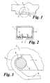
- Figure 1 illustrates a side view of part of a windscreen wiper support head of this invention;
- Figure 2 is a vertical section through the support head of Figure 1;
- Figure 3 is an enlargement of part of the assembly in Figures 1 and 2, illustrating the location of the hooked end of a spring;
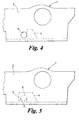
- Figure 4 is a side view illustration of an alternative wiper support head construction of the invention; and
- Figure 5 shows a still further example of a windscreen wiper support head of the invention.
-
- As shown in the example of Figures 1 to 3, a windscreen
wiper support head 1 has a pair ofside walls 2 defining inturnedarms 3 terminating in upturned bearingwalls 4 located at the position as shown in dashed outline in Figure 1. Thebearing walls 4 each incorporate anotch 5 at their outer faces into which can be located apin 6 in the manner as indicated in Figure 3. The hooked end 7 of aspring 8 can then be located over the pin. The pressure of the spring holds the pin in place in thenotch 5, enabling the pin also to act as a location anchorage for the hooked end 7 of the spring. - In the arrangement shown in Figure 4, the
bearing walls 4 are plain in configuration and do not necessarily incorporate anotch 5. However, holes 9 are provided in theside walls 2 to allow apin 6 to be fed through, with the ends of the pin being supported in those holes in theside walls 2. Thebearing walls 4 provide added support for thepin 6 against the pressure exerted by thespring 8. - As shown in Figure 5, the
bearing walls 4 could be arranged to have a forwardly extending portion 10 defining a key-shaped opening 11. Apin 6 can then be introduced from below and pressed as a snap-fit into the keyhole shapedrecess 11.
Claims (7)
- A support head of a windscreen wiper assembly incorporating a mounting arrangement for a location pin for holding the end of a spring which biases the pivoted support head of the windscreen wiper assembly into a lowered condition, the support head having a top face and two side walls, the mounting arrangement comprising inturned arms from the two side walls of the head, the arms terminating in upturned bearing walls to receive the location pin.
- A support head according to Claim 1, wherein the bearing walls incorporate notches to locate the pin in a desired position.
- A support head according to Claim 2, wherein each notch opens into a face of the bearing wall which is directed towards the base of the support head.
- A support head according to Claim 3, wherein the notch is keyhole-shaped to enable the pin to be snap-fitted into place.
- A support head according to any one of Claims 1 to 4, wherein one or both of the side walls of the head incorporates a hole for receipt of an end of the pin.
- A support head substantially as herein described with reference to the accompanying drawings.
- Any novel combination of features of a support head of a windscreen wiper assembly as described herein and/or as shown in the accompanying drawings.
Applications Claiming Priority (2)
| Application Number | Priority Date | Filing Date | Title |
|---|---|---|---|
| GB0015464 | 2000-06-24 | ||
| GBGB0015464.1A GB0015464D0 (en) | 2000-06-24 | 2000-06-24 | Improvements relating to windscreen wipers |
Publications (3)
| Publication Number | Publication Date |
|---|---|
| EP1167136A2 true EP1167136A2 (en) | 2002-01-02 |
| EP1167136A3 EP1167136A3 (en) | 2002-08-07 |
| EP1167136B1 EP1167136B1 (en) | 2004-09-22 |
Family
ID=9894301
Family Applications (1)
| Application Number | Title | Priority Date | Filing Date |
|---|---|---|---|
| EP01305386A Expired - Lifetime EP1167136B1 (en) | 2000-06-24 | 2001-06-21 | Improvements relating to windscreen wipers |
Country Status (4)
| Country | Link |
|---|---|
| EP (1) | EP1167136B1 (en) |
| AT (1) | ATE276903T1 (en) |
| DE (1) | DE60105697D1 (en) |
| GB (2) | GB0015464D0 (en) |
Cited By (1)
| Publication number | Priority date | Publication date | Assignee | Title |
|---|---|---|---|---|
| WO2008080668A1 (en) * | 2006-12-28 | 2008-07-10 | Robert Bosch Gmbh | Wiper arm |
Family Cites Families (5)
| Publication number | Priority date | Publication date | Assignee | Title |
|---|---|---|---|---|
| IT206952Z2 (en) * | 1986-05-08 | 1987-10-26 | Champion Spark Plug Italiana | CONTROL ARM FOR WIPER SPATULAS WITH SPIRAL SPRING |
| DE3829466C2 (en) * | 1988-08-31 | 1999-06-02 | Teves Gmbh Alfred | Wiper arm |
| FR2693693B1 (en) * | 1992-07-15 | 1994-08-19 | Valeo Systemes Dessuyage | Wiper arms. |
| FR2724897B1 (en) * | 1994-09-23 | 1996-12-13 | Valeo Systemes Dessuyage | MOTOR VEHICLE WINDSCREEN WIPER COMPRISING IMPROVED MEANS FOR HANGING THE WIPING SPRING |
| GB2311461B (en) * | 1996-03-23 | 1999-04-21 | Trico Ltd | Improvements relating to mounting arrangements |
-
2000
- 2000-06-24 GB GBGB0015464.1A patent/GB0015464D0/en not_active Ceased
-
2001
- 2001-06-21 AT AT01305386T patent/ATE276903T1/en not_active IP Right Cessation
- 2001-06-21 GB GB0115193A patent/GB2363706B/en not_active Revoked
- 2001-06-21 DE DE60105697T patent/DE60105697D1/en not_active Expired - Lifetime
- 2001-06-21 EP EP01305386A patent/EP1167136B1/en not_active Expired - Lifetime
Non-Patent Citations (1)
| Title |
|---|
| None |
Cited By (1)
| Publication number | Priority date | Publication date | Assignee | Title |
|---|---|---|---|---|
| WO2008080668A1 (en) * | 2006-12-28 | 2008-07-10 | Robert Bosch Gmbh | Wiper arm |
Also Published As
| Publication number | Publication date |
|---|---|
| GB2363706A (en) | 2002-01-09 |
| GB0115193D0 (en) | 2001-08-15 |
| EP1167136B1 (en) | 2004-09-22 |
| GB0015464D0 (en) | 2000-08-16 |
| ATE276903T1 (en) | 2004-10-15 |
| EP1167136A3 (en) | 2002-08-07 |
| GB2363706B (en) | 2003-12-24 |
| DE60105697D1 (en) | 2004-10-28 |
Similar Documents
| Publication | Publication Date | Title |
|---|---|---|
| ES2276977T3 (en) | WASHERS WITH AN ARM WINDSHIELD. | |
| US6055697A (en) | Windshield wiper blade | |
| US9021652B2 (en) | Connecting element for the articulated connection of a wiper blade to a wiper arm | |
| US6308373B1 (en) | Wiper blade for motor vehicle windshields | |
| US8191201B2 (en) | Connection element | |
| CN100564116C (en) | Adapter for the articulation of a wiper blade to a wiper arm | |
| US7793382B2 (en) | Wiper arm and cover for a wiper arm | |
| CN101094781B (en) | wiper device | |
| US5647088A (en) | Wiper with a wind guide device | |
| EP1568559A1 (en) | A windscreen wiper device | |
| US20040074037A1 (en) | Windscreen wiper with a wiper arm | |
| US20060112511A1 (en) | Wiping device for windows of motor vehicles | |
| US20050262653A1 (en) | Wiper lever with a driven wiper arm and a wiper blade linked to it for cleaning the windows of motor vehicles in particular | |
| CN102548811A (en) | Wiper blade | |
| JP2003500290A (en) | Wiper device for windshield of automobile | |
| US6058555A (en) | Wiper blade with wind-deflecting surface for windshield wiper systems of motor vehicles | |
| US20040140663A1 (en) | Mud flap hanger system | |
| EP1637419A2 (en) | Windshield wiper for automotive vehicles | |
| EP0285262B1 (en) | Wiperblade of windshield wiper | |
| EP1167136A2 (en) | Improvements relating to windscreen wipers | |
| US6209166B1 (en) | Windshield wiper | |
| JPH11512994A (en) | Wiper blade for automotive window glass | |
| EP0845394B1 (en) | A windscreen wiper arm | |
| US6473932B1 (en) | Wiper arm | |
| CN103260965B (en) | Wiper, in particular for the windshield wiper of self-propelled vehicle |
Legal Events
| Date | Code | Title | Description |
|---|---|---|---|
| PUAI | Public reference made under article 153(3) epc to a published international application that has entered the european phase |
Free format text: ORIGINAL CODE: 0009012 |
|
| AK | Designated contracting states |
Kind code of ref document: A2 Designated state(s): AT BE CH CY DE DK ES FI FR GB GR IE IT LI LU MC NL PT SE TR |
|
| AX | Request for extension of the european patent |
Free format text: AL;LT;LV;MK;RO;SI |
|
| PUAL | Search report despatched |
Free format text: ORIGINAL CODE: 0009013 |
|
| AK | Designated contracting states |
Kind code of ref document: A3 Designated state(s): AT BE CH CY DE DK ES FI FR GB GR IE IT LI LU MC NL PT SE TR |
|
| AX | Request for extension of the european patent |
Free format text: AL;LT;LV;MK;RO;SI |
|
| 17P | Request for examination filed |
Effective date: 20030207 |
|
| AKX | Designation fees paid |
Designated state(s): AT BE CH CY DE DK ES FI FR GB GR IE IT LI LU MC NL PT SE TR |
|
| 17Q | First examination report despatched |
Effective date: 20030703 |
|
| GRAP | Despatch of communication of intention to grant a patent |
Free format text: ORIGINAL CODE: EPIDOSNIGR1 |
|
| RAP1 | Party data changed (applicant data changed or rights of an application transferred) |
Owner name: TRICO PRODUCTS CORPORATION |
|
| GRAS | Grant fee paid |
Free format text: ORIGINAL CODE: EPIDOSNIGR3 |
|
| GRAA | (expected) grant |
Free format text: ORIGINAL CODE: 0009210 |
|
| AK | Designated contracting states |
Kind code of ref document: B1 Designated state(s): AT BE CH CY DE DK ES FI FR GB GR IE IT LI LU MC NL PT SE TR |
|
| PG25 | Lapsed in a contracting state [announced via postgrant information from national office to epo] |
Ref country code: IT Free format text: LAPSE BECAUSE OF FAILURE TO SUBMIT A TRANSLATION OF THE DESCRIPTION OR TO PAY THE FEE WITHIN THE PRESCRIBED TIME-LIMIT;WARNING: LAPSES OF ITALIAN PATENTS WITH EFFECTIVE DATE BEFORE 2007 MAY HAVE OCCURRED AT ANY TIME BEFORE 2007. THE CORRECT EFFECTIVE DATE MAY BE DIFFERENT FROM THE ONE RECORDED. Effective date: 20040922 Ref country code: AT Free format text: LAPSE BECAUSE OF FAILURE TO SUBMIT A TRANSLATION OF THE DESCRIPTION OR TO PAY THE FEE WITHIN THE PRESCRIBED TIME-LIMIT Effective date: 20040922 Ref country code: BE Free format text: LAPSE BECAUSE OF FAILURE TO SUBMIT A TRANSLATION OF THE DESCRIPTION OR TO PAY THE FEE WITHIN THE PRESCRIBED TIME-LIMIT Effective date: 20040922 Ref country code: NL Free format text: LAPSE BECAUSE OF FAILURE TO SUBMIT A TRANSLATION OF THE DESCRIPTION OR TO PAY THE FEE WITHIN THE PRESCRIBED TIME-LIMIT Effective date: 20040922 Ref country code: FI Free format text: LAPSE BECAUSE OF FAILURE TO SUBMIT A TRANSLATION OF THE DESCRIPTION OR TO PAY THE FEE WITHIN THE PRESCRIBED TIME-LIMIT Effective date: 20040922 Ref country code: TR Free format text: LAPSE BECAUSE OF FAILURE TO SUBMIT A TRANSLATION OF THE DESCRIPTION OR TO PAY THE FEE WITHIN THE PRESCRIBED TIME-LIMIT Effective date: 20040922 Ref country code: CH Free format text: LAPSE BECAUSE OF FAILURE TO SUBMIT A TRANSLATION OF THE DESCRIPTION OR TO PAY THE FEE WITHIN THE PRESCRIBED TIME-LIMIT Effective date: 20040922 Ref country code: FR Free format text: LAPSE BECAUSE OF FAILURE TO SUBMIT A TRANSLATION OF THE DESCRIPTION OR TO PAY THE FEE WITHIN THE PRESCRIBED TIME-LIMIT Effective date: 20040922 Ref country code: LI Free format text: LAPSE BECAUSE OF FAILURE TO SUBMIT A TRANSLATION OF THE DESCRIPTION OR TO PAY THE FEE WITHIN THE PRESCRIBED TIME-LIMIT Effective date: 20040922 |
|
| REG | Reference to a national code |
Ref country code: GB Ref legal event code: FG4D |
|
| REG | Reference to a national code |
Ref country code: CH Ref legal event code: EP |
|
| REG | Reference to a national code |
Ref country code: IE Ref legal event code: FG4D |
|
| REF | Corresponds to: |
Ref document number: 60105697 Country of ref document: DE Date of ref document: 20041028 Kind code of ref document: P |
|
| PG25 | Lapsed in a contracting state [announced via postgrant information from national office to epo] |
Ref country code: DK Free format text: LAPSE BECAUSE OF FAILURE TO SUBMIT A TRANSLATION OF THE DESCRIPTION OR TO PAY THE FEE WITHIN THE PRESCRIBED TIME-LIMIT Effective date: 20041222 Ref country code: SE Free format text: LAPSE BECAUSE OF FAILURE TO SUBMIT A TRANSLATION OF THE DESCRIPTION OR TO PAY THE FEE WITHIN THE PRESCRIBED TIME-LIMIT Effective date: 20041222 Ref country code: GR Free format text: LAPSE BECAUSE OF FAILURE TO SUBMIT A TRANSLATION OF THE DESCRIPTION OR TO PAY THE FEE WITHIN THE PRESCRIBED TIME-LIMIT Effective date: 20041222 |
|
| PG25 | Lapsed in a contracting state [announced via postgrant information from national office to epo] |
Ref country code: DE Free format text: LAPSE BECAUSE OF FAILURE TO SUBMIT A TRANSLATION OF THE DESCRIPTION OR TO PAY THE FEE WITHIN THE PRESCRIBED TIME-LIMIT Effective date: 20041223 |
|
| PG25 | Lapsed in a contracting state [announced via postgrant information from national office to epo] |
Ref country code: ES Free format text: LAPSE BECAUSE OF FAILURE TO SUBMIT A TRANSLATION OF THE DESCRIPTION OR TO PAY THE FEE WITHIN THE PRESCRIBED TIME-LIMIT Effective date: 20050102 |
|
| REG | Reference to a national code |
Ref country code: CH Ref legal event code: PL |
|
| NLV1 | Nl: lapsed or annulled due to failure to fulfill the requirements of art. 29p and 29m of the patents act | ||
| PG25 | Lapsed in a contracting state [announced via postgrant information from national office to epo] |
Ref country code: CY Free format text: LAPSE BECAUSE OF FAILURE TO SUBMIT A TRANSLATION OF THE DESCRIPTION OR TO PAY THE FEE WITHIN THE PRESCRIBED TIME-LIMIT Effective date: 20050621 |
|
| PGFP | Annual fee paid to national office [announced via postgrant information from national office to epo] |
Ref country code: FR Payment date: 20050627 Year of fee payment: 5 |
|
| PGFP | Annual fee paid to national office [announced via postgrant information from national office to epo] |
Ref country code: IE Payment date: 20050628 Year of fee payment: 5 Ref country code: MC Payment date: 20050628 Year of fee payment: 5 |
|
| PGFP | Annual fee paid to national office [announced via postgrant information from national office to epo] |
Ref country code: LU Payment date: 20050705 Year of fee payment: 5 |
|
| PLBE | No opposition filed within time limit |
Free format text: ORIGINAL CODE: 0009261 |
|
| STAA | Information on the status of an ep patent application or granted ep patent |
Free format text: STATUS: NO OPPOSITION FILED WITHIN TIME LIMIT |
|
| 26N | No opposition filed |
Effective date: 20050623 |
|
| EN | Fr: translation not filed | ||
| PG25 | Lapsed in a contracting state [announced via postgrant information from national office to epo] |
Ref country code: IE Free format text: LAPSE BECAUSE OF NON-PAYMENT OF DUE FEES Effective date: 20060621 |
|
| PG25 | Lapsed in a contracting state [announced via postgrant information from national office to epo] |
Ref country code: MC Free format text: LAPSE BECAUSE OF NON-PAYMENT OF DUE FEES Effective date: 20060630 |
|
| REG | Reference to a national code |
Ref country code: IE Ref legal event code: MM4A |
|
| PG25 | Lapsed in a contracting state [announced via postgrant information from national office to epo] |
Ref country code: PT Free format text: LAPSE BECAUSE OF NON-PAYMENT OF DUE FEES Effective date: 20050222 |
|
| PG25 | Lapsed in a contracting state [announced via postgrant information from national office to epo] |
Ref country code: LU Free format text: LAPSE BECAUSE OF NON-PAYMENT OF DUE FEES Effective date: 20060621 |
|
| PGFP | Annual fee paid to national office [announced via postgrant information from national office to epo] |
Ref country code: GB Payment date: 20150617 Year of fee payment: 15 |
|
| GBPC | Gb: european patent ceased through non-payment of renewal fee |
Effective date: 20160621 |
|
| PG25 | Lapsed in a contracting state [announced via postgrant information from national office to epo] |
Ref country code: GB Free format text: LAPSE BECAUSE OF NON-PAYMENT OF DUE FEES Effective date: 20160621 |