EP2107591A1 - Multistage gas cascade amplifier - Google Patents
Multistage gas cascade amplifier Download PDFInfo
- Publication number
- EP2107591A1 EP2107591A1 EP09156789A EP09156789A EP2107591A1 EP 2107591 A1 EP2107591 A1 EP 2107591A1 EP 09156789 A EP09156789 A EP 09156789A EP 09156789 A EP09156789 A EP 09156789A EP 2107591 A1 EP2107591 A1 EP 2107591A1
- Authority
- EP
- European Patent Office
- Prior art keywords
- electrode
- sample
- detector
- stage
- gas
- Prior art date
- Legal status (The legal status is an assumption and is not a legal conclusion. Google has not performed a legal analysis and makes no representation as to the accuracy of the status listed.)
- Withdrawn
Links
- 230000003321 amplification Effects 0.000 claims abstract description 93
- 238000003199 nucleic acid amplification method Methods 0.000 claims abstract description 93
- 230000015556 catabolic process Effects 0.000 claims abstract description 51
- 239000002245 particle Substances 0.000 claims abstract description 28
- 150000002500 ions Chemical class 0.000 claims description 76
- 238000000034 method Methods 0.000 claims description 22
- 230000005684 electric field Effects 0.000 claims description 16
- 238000003384 imaging method Methods 0.000 claims description 15
- 230000003472 neutralizing effect Effects 0.000 claims description 9
- 238000006386 neutralization reaction Methods 0.000 claims description 7
- 230000033001 locomotion Effects 0.000 claims description 4
- 239000012528 membrane Substances 0.000 claims description 4
- 238000004020 luminiscence type Methods 0.000 claims description 3
- 239000002800 charge carrier Substances 0.000 claims description 2
- 239000004020 conductor Substances 0.000 abstract 1
- 239000007789 gas Substances 0.000 description 89
- 238000002834 transmittance Methods 0.000 description 14
- 230000008901 benefit Effects 0.000 description 9
- 230000008569 process Effects 0.000 description 8
- 230000007423 decrease Effects 0.000 description 5
- 238000009826 distribution Methods 0.000 description 5
- 230000000694 effects Effects 0.000 description 5
- 230000006798 recombination Effects 0.000 description 5
- 238000005215 recombination Methods 0.000 description 5
- 238000004458 analytical method Methods 0.000 description 4
- 238000010894 electron beam technology Methods 0.000 description 3
- 238000004519 manufacturing process Methods 0.000 description 3
- 239000000203 mixture Substances 0.000 description 3
- 239000011163 secondary particle Substances 0.000 description 3
- OKTJSMMVPCPJKN-UHFFFAOYSA-N Carbon Chemical compound [C] OKTJSMMVPCPJKN-UHFFFAOYSA-N 0.000 description 2
- 229910052799 carbon Inorganic materials 0.000 description 2
- 238000001514 detection method Methods 0.000 description 2
- 239000000463 material Substances 0.000 description 2
- 230000007246 mechanism Effects 0.000 description 2
- 230000003287 optical effect Effects 0.000 description 2
- XLYOFNOQVPJJNP-UHFFFAOYSA-N water Chemical compound O XLYOFNOQVPJJNP-UHFFFAOYSA-N 0.000 description 2
- 125000003821 2-(trimethylsilyl)ethoxymethyl group Chemical group [H]C([H])([H])[Si](C([H])([H])[H])(C([H])([H])[H])C([H])([H])C(OC([H])([H])[*])([H])[H] 0.000 description 1
- ATJFFYVFTNAWJD-UHFFFAOYSA-N Tin Chemical compound [Sn] ATJFFYVFTNAWJD-UHFFFAOYSA-N 0.000 description 1
- 230000004075 alteration Effects 0.000 description 1
- 229910003481 amorphous carbon Inorganic materials 0.000 description 1
- 238000013459 approach Methods 0.000 description 1
- 239000012620 biological material Substances 0.000 description 1
- 230000005540 biological transmission Effects 0.000 description 1
- 239000011248 coating agent Substances 0.000 description 1
- 238000000576 coating method Methods 0.000 description 1
- 238000010276 construction Methods 0.000 description 1
- 230000007547 defect Effects 0.000 description 1
- 238000002389 environmental scanning electron microscopy Methods 0.000 description 1
- 238000001704 evaporation Methods 0.000 description 1
- 238000000605 extraction Methods 0.000 description 1
- 230000002349 favourable effect Effects 0.000 description 1
- 230000004907 flux Effects 0.000 description 1
- 238000002347 injection Methods 0.000 description 1
- 239000007924 injection Substances 0.000 description 1
- 238000005457 optimization Methods 0.000 description 1
- 238000004626 scanning electron microscopy Methods 0.000 description 1
- 230000035945 sensitivity Effects 0.000 description 1
- 239000000243 solution Substances 0.000 description 1
- 238000006467 substitution reaction Methods 0.000 description 1
- 239000000758 substrate Substances 0.000 description 1
- 230000001629 suppression Effects 0.000 description 1
- 238000011144 upstream manufacturing Methods 0.000 description 1
Images


Classifications
-
- H—ELECTRICITY
- H01—ELECTRIC ELEMENTS
- H01J—ELECTRIC DISCHARGE TUBES OR DISCHARGE LAMPS
- H01J37/00—Discharge tubes with provision for introducing objects or material to be exposed to the discharge, e.g. for the purpose of examination or processing thereof
- H01J37/02—Details
- H01J37/244—Detectors; Associated components or circuits therefor
-
- H—ELECTRICITY
- H01—ELECTRIC ELEMENTS
- H01J—ELECTRIC DISCHARGE TUBES OR DISCHARGE LAMPS
- H01J37/00—Discharge tubes with provision for introducing objects or material to be exposed to the discharge, e.g. for the purpose of examination or processing thereof
- H01J37/26—Electron or ion microscopes; Electron or ion diffraction tubes
- H01J37/28—Electron or ion microscopes; Electron or ion diffraction tubes with scanning beams
-
- H—ELECTRICITY
- H01—ELECTRIC ELEMENTS
- H01J—ELECTRIC DISCHARGE TUBES OR DISCHARGE LAMPS
- H01J47/00—Tubes for determining the presence, intensity, density or energy of radiation or particles
- H01J47/06—Proportional counter tubes
-
- H—ELECTRICITY
- H01—ELECTRIC ELEMENTS
- H01J—ELECTRIC DISCHARGE TUBES OR DISCHARGE LAMPS
- H01J2237/00—Discharge tubes exposing object to beam, e.g. for analysis treatment, etching, imaging
- H01J2237/244—Detection characterized by the detecting means
- H01J2237/2444—Electron Multiplier
- H01J2237/24445—Electron Multiplier using avalanche in a gas
-
- H—ELECTRICITY
- H01—ELECTRIC ELEMENTS
- H01J—ELECTRIC DISCHARGE TUBES OR DISCHARGE LAMPS
- H01J2237/00—Discharge tubes exposing object to beam, e.g. for analysis treatment, etching, imaging
- H01J2237/244—Detection characterized by the detecting means
- H01J2237/2448—Secondary particle detectors
-
- H—ELECTRICITY
- H01—ELECTRIC ELEMENTS
- H01J—ELECTRIC DISCHARGE TUBES OR DISCHARGE LAMPS
- H01J2237/00—Discharge tubes exposing object to beam, e.g. for analysis treatment, etching, imaging
- H01J2237/26—Electron or ion microscopes
- H01J2237/2602—Details
- H01J2237/2605—Details operating at elevated pressures, e.g. atmosphere
Definitions
- the present invention relates to cascade detectors for charged particle beam systems.
- a scanning electron microscope scans a primary beam of electrons along a sample surface and detects the secondary electrons that are emitted. An image is formed, with the intensity at each image point being proportional to the number of secondary electrons detected at the corresponding point on the sample.
- Most electron microscopes operate in a high vacuum to prevent scattering of the primary electron beam.
- Such electron microscopes typically use a secondary electron detector called an Everhard-Thornley detector, which includes a scintillator that emits light when struck by a secondary electron and a photomultiplier tube that amplifies the light to produce an electrical output signal.
- a photo multiplier tube typically has a gain of about 106 that is, for each electron that enters the detector, about one million electrons are generated for detection.
- Such SEMs cannot observe moist samples, such as biological tissue, because the evaporating moisture scatters the primary beam and the vacuum dries the sample.
- HPSEM High Pressure Scanning Electron Microscopes
- ESEM® Electron Microscopes from FEI Company, the assignee of the present invention
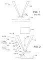
- FIG. 1 shows an HPSEM 100 similar to the one described in U.S. Pat. No. 4,785,182 to Mancuso, et al.
- HPSEM 100 includes an objective lens 102 to which is attached a pressure limiting aperture 104 that allows electrons to move from the upper column to a sample 106, but restricts the flow of gas into the evacuated electron column.
- the pressure limiting aperture 104 allows the pressure in the sample chamber to be significantly higher than the pressure in the electron beam column above aperture 104, so that electrons are not scattered by gas molecules along most of their path.
- a positive voltage relative to sample 106 is applied to a detector 110, which consists of an electrode that is concentric with the optical axis. Secondary particles emitted from the sample 106 are accelerated toward the detector 110 and collide with gas molecules, producing additional charged particles, which in turn collide with other gas molecules to produce even more charged particles. Such a process is called a "cascade.” The ultimate number of charged particles produced in this manner is proportional to the number of secondary particles emitted at the substrate, thereby producing an amplified signal corresponding to the number of secondary particles.
- the electron source and much of the path of the primary beam is maintained in a high vacuum by the aperture 104 that passes the primary beam but prevents most gas molecules from entering the column. Gas pressure at the sample in an HPSEM is typically maintained at around 0.1 to 50 Torr (0.13 to 66.67 mbar), and more typically between 0.5 and 5 Torr (0.67 to 6.67 mbar).
- the amplification of the secondary electron signal in an HPSEM depends on the gas pressure, the electron path length, and the voltage between the sample and the detector.
- the amplification is typically much lower that that of an ET detector.
- Higher gas pressure allows for more collision and may better preserve some types of samples, such as hydrated biomaterials, but too high a pressure impedes the gas cascade and reduces the amplified imaging signal.
- a longer path length generally results in more collisions.
- Magnetic and electric fields can be used to increase the path length of the secondary electrons to provide greater amplification.
- 6,972,412 for "Particle-Optical Device and Detection Means" to Scholtz et al. assigned to the assignee of the present invention, describes using magnetic and electric fields between the detector and the specimen holder to lengthen the path of the secondary electrons to produce increased amplification.
- Increasing the voltage between the sample and the detector provides more energy to the electrons to ionize gas molecules. Too high a voltage, however, causes dielectric breakdown of the gas, that is, a self-sustaining gas ionization cascade. The signal is then no longer proportional to the secondary electron current produced by the primary beam and is no longer useful for forming an image of the sample.
- WO 2004/059691 of Jacka, et al. uses an off axis detector chamber that is maintained at a lower pressure than the sample chamber.
- a grid referred to as a Frisch grid, positioned in front of the detector entrance attracts electrons, which pass through a pressure limiting grid to enter a differentially pumped chamber. Because the chamber interior is maintained at a lower pressure than the sample chamber, the high voltage required by a scintillator detector does not cause breakdown of the gas.
- the amplification of the secondary electron signal in an HPSEM is limited by a number of factors. It would be desirable to increase the amplification to improve the sensitivity of the microscope.
- the purpose of the invention is to provide a solution to the defects of the prior art.
- An object of the invention is to improve secondary electron signal amplification in an HPSEM.
- This invention provides for a detector for a HPSEM that includes multiple gas cascade amplification stages.
- the stages are typically defined by electrodes to which voltages are applied relative to the sample or to a previous stage.
- FIG. 1 shows a prior art HPSEM with a one-stage HPSEM detector.
- FIG. 2 shows an HPSEM with a three-stage detector embodiment of the invention.
- FIG. 3 shows an HPSEM with a four-stage detector embodiment of the invention.
- FIG. 4 shows an HPSEM with a two-stage detector embodiment of the invention.
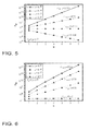
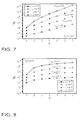
- FIGS. 5-8 are graphs showing the breakdown gain as a function of the total number of stages, calculated for different values of the electron ejection probabilities and grid transmittances.
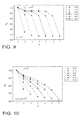
- FIGS. 9-12 are graphs showing the gain in each stage as a function of stage number, calculated at the point of breakdown for different grid transmittances.
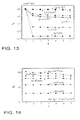
- FIG. 14 is a graph showing the gain in each stage as a function of stage number at a number of pre-feedback and total system gains.
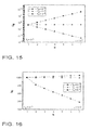
- FIGS. 15-16 are graphs showing the breakdown gain as a function of the total number of stages, calculated for different values of the electron ejection probabilities and grid transmittances.
- FIG. 17 is a graph showing the breakdown gain as a function of the total number of stages, calculated for a range of pre-feedback gain distributions.
- FIG. 18 is a graph showing the gain in each stage of a 5 stage system, calculated for a range of pre-feedback gain distributions.
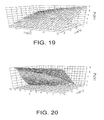
- FIG. 19 is a graph showing the breakdown gain of a 2 stage system as a function of the electron and ion grid transmittances.
- FIG. 20 is a graph showing the breakdown gain of a 2 stage system as a function of the electron ejection probability from a grid impacted by ions, and the pre-feedback gain ratio of stage 2 relative to stage 1.
- the present invention greatly increases the maximum gain and reduces noise in a cascade detector, that is, a detector using gas amplification.
- the maximum gain in a cascade detector is limited in many prior art systems by dielectric breakdown of the gas.
- the dominant breakdown mechanism is believed to be feedback in the gas cascade caused by electron injection into the cascade as a result of ion recombination or neutralization at the sample and surfaces, such as the lens pole piece, inside the specimen chamber.
- the ion neutralization generates additional electrons, referred to here as "tertiary electrons", which then accelerate toward the anode, generating additional electrons and ions which in turn generate additional electrons upon neutralization.
- the unwanted feedback generates an electron signal that eventually becomes self-sustaining and swamps the useful imaging signal from the sample.
- the feedback component of the gas cascade amplification process serves to increase noise due to the statistical nature of the tertiary electron generation process.
- Embodiments of the invention provide multiple amplification regions, each region amplifying the electron signal from the previous region, with the anode positioned toward the end of the final amplification region.
- the amplification regions comprise a detector volume, which, typically extends from the sample surface to the anode.
- the electrical potential increases from one amplification region to the next in the direction of the anode. As gaseous ions are created, they are neutralized in the region in which they are created, or in a previous, lower potential region, that is, a region closer to the sample.
- the potential field in the amplification regions can be produced and shaped by electrodes, such as grids, porous members or other types of electrodes.
- electrodes such as grids, porous members or other types of electrodes.
- some embodiments of the invention provide one or more electrodes positioned between the anode and the sample, to provide surfaces for ions generated in the gas to neutralize, that is, to recombine with electrons.
- the electrodes are preferably semitransparent to electrons accelerated toward the electrode from the sample or the previous amplification stage.
- the electrode may also be semi-transparent to gaseous ions that drift back toward the previous stage or sample.
- the invention is not limited to a specific type of imaging signal.
- the imaging signal can be derived, for example, from an electrical signal induced in an electrode, such as the anode or another electrode, by charge flow in the gas.
- the imaging signal can also be derived from an electron current collected by the anode, an ion current collected by a cathode, or a luminescence signal generated by the gas cascade.
- embodiments of the invention use multiple gas amplification stages to increase the maximum gain attainable before the onset of dielectric breakdown of the gas.
- the modeling results described below show that, in the absence of other gas breakdown mechanisms and ion-induced space charge effects, the maximum gain can be made to increase with the number of amplification stages. In practice, effects such as ion-induced space charges may limit ultimate gain.
- the present invention can control the feedback in the gas cascade to provide gas gains greater than those attainable by existing cascade detectors.
- Benefits of multi-stage amplification are believed to stem from the ability to control the fraction of ions that recombine in each stage, which is thought to affect the breakdown of the gas. Controlling the fraction of ions that recombine in each stage provides at least two benefits. First, breakdown gain can be increased by increasing the number of gas amplification stages. Second, cascade noise can be controlled by minimizing feedback within each stage whilst maintaining a given total system gain.
- Detectors in accordance with the invention having multiple stages can be configured to simultaneously optimize multiple factors.
- the first stage can be designed to optimize secondary electron extraction efficiency and charge control, by controlling the electric field in the first stage and by controlling the ion flux at the sample surface.
- the last stage can then be designed to optimize detector bandwidth by optimizing the distance between the anode and the final grid and the electrostatic transparency of the final grid.
- the total number of stages and the extent of amplification within each stage can be designed to optimized net system gain and net system noise.
- FIG. 2 shows an HPSEM 200 including a preferred three stage detector 202 embodying the present invention.
- a beam of primary electrons 204 from a source of electrons, such as an electron column 205 impacts the sample 106, which is positioned in a sample chamber containing a gaseous atmosphere, for example, of water vapor at a pressure of between 1 Torr (1.3 mbar) and 5 Torr (6.7 mbar).
- Secondary electrons 206 are emitted from the sample 106 and accelerate toward first conductive grid 210, also referred to as an electrode, which is biased positive relative to sample 106.
- Secondary electrons 206 collide with gas molecules 216, ionizing them and creating additional electron that accelerate toward first conductive grid 210 near the entrance of a detector chamber 218. The ionized gas molecules accelerate toward the sample, moving much slower than the electrons.
- a second conductive grid (or electrode) 220 biased positively with respect to the first conductive grid, accelerates the electrons 206 transmitted through the first conductive grid 210. While moving from first conductive grid 210 to second conductive grid 220, electrons 206 collide with additional gas molecules 216 and further amplify the secondary electron signal.
- An anode 222 mounted toward the rear of detector chamber 218 and biased positive relative to the second conductive grid 220 collects the electrons 206 and is used to detect an electric current, which is amplified by an amplifier 230 and processed by a video processor 232 together with position information about the primary electron beam, to produce an image of the sample 106, which is displayed on display 234.
- the sample is maintained at a potential of about 0 volts
- first conductive grid 210 is maintained at a potential of about 100 V
- second conductive grid 220 is maintained at a potential of about 300 V
- anode 22 is maintained at a potential of about 600 V.
- First conductive grid 210 is preferably positioned about 10 mm from sample 106; second conductive grid 220 is preferably spaced about 10 mm from first conductive grid 210; and anode 222 is preferably spaced about 10 mm from second conductive grid 220.
- one or more of the conductive grids in any of the embodiments may be coated with a material, such as amorphous carbon, that exhibits reduced secondary electron emission when impacted by charged particles.
- Conductive grid 220 provides a surface at which ions produced between grid 220 and anode 222 can neutralize by recombining with an electron from the grid. If the recombination produces additional electrons, such as Auger electrons or photoelectrons, those electrons travel only from grid 220 to anode 222. If there were no opportunity for the ions to recombine with electrons before reaching sample 106, the tertiary electrons created by the recombination would travel across a much greater potential difference and would be amplified much more in the gas cascade. Amplification of these tertiary electrons serves to increase feedback which eventually causes breakdown of the gas (i.e., a self-sustaining gas cascade that overwhelms the useful signal from the sample).
- conductive grid 210 provides a surface at which ions produced between grid 210 and anode 222 can neutralize by recombining with an electron from the grid 210.
- stage 1 is created by the sample 106 and conductive grid 210
- stage 2 is created by conductive grid 210 and conductive grid 220
- stage 3 is created by conductive grid 220 and anode 222.
- FIG. 3 shows another embodiment of an HPSEM 300, similar to that of FIG. 2 , but having a detector 302 including four stages created by conductive grids 210, 310 and 312 and the anode 322. Additional stages provide additional amplification prior to the onset of breakdown. Operating parameters are similar to those of the embodiment of FIG. 2 , and skilled persons can readily determine appropriate operating parameters for the embodiment of FIG. 3 from information provided herein with regard to other embodiments.
- FIG. 4 shows another embodiment of an HPSEM 400 that include a two-stage detector 402 having a single conductive screen 210. While detector 402 includes only a single conductive screen, the electron path from the sample to the conductive screen 210 can be considered a first stage, while the electron path from conductive screen 210 to anode 222 can be considered a second stage.
- Sample 106 is preferably maintained at about 0 V
- conductive screen 210 is preferably maintained at about 200 V
- anode 222 is preferably maintained at about 500 V.
- Conductive screen 210 is preferably positioned about 10 mm from sample 106, and anode 222 is preferably spaced about 10 mm from conductive screen 210.
- the gain of the second stage is at least 1 ⁇ 2 the gain of the first stage, and more preferably at least the same as or twice the gain of the first stage.
- FIG. 4 While the embodiment of FIG. 4 superficially appears to be similar to the system described by Phillips et al., Phillips teaches that the conductive grid is positioned very near the anode so that very few ions are created between his grid and the anode. In the embodiment of FIG. 4 , conductive screen 210 is positioned sufficiently far from the anode 222 so that additional ions are created to further amplify the signal. In fact, the results shown in FIGS. 5-20 and discussed below show that optimal performance is realized when two criteria are satisfied. First, the gain and hence the ion generation rate between the grid and the anode must be greater than the ion generation rate between the sample and the grid. Second, the grid must collect as many of the ions generated in the gas cascade as possible.
- G J 1 / J 0
- F J 1 - J 0 ⁇ ⁇ J 0
- Equation 1 Equation 1 + ⁇ ⁇ ⁇ J 0 - J 0 ⁇ ⁇ + J 1 ⁇ ⁇
- J 1 ⁇ 1 ⁇ J 0 + J 1 - J 0 ⁇ ⁇ 1 + J 2 - T e ⁇ 1 ⁇ J 1 ⁇ T i ⁇ 1 ⁇ ⁇ 1
- J 2 ⁇ 2 ⁇ T e ⁇ 1 ⁇ J 1 + J 2 - T e ⁇ 1 ⁇ J 1 ⁇ 1 - T i ⁇ 1 ⁇ ⁇ 2
- G J 2 / J 0
- the "net feedback" of a multi stage amplifier is not a meaningful concept because a distinct feedback loop is created in each stage.
- the only parameters of relevance are the feedback coefficient ( ⁇ n ) and “feedback” (F n ) of each stage n. Gas breakdown occurs when any one of the F n values reaches unity. The sum ⁇ F n can exceed unity.
- Each stage "m” also feeds back into each previous stage “n” (whereby n ⁇ m) due to ion transmission through the grids. This effect is accounted for by the above equations.
- J 1 ⁇ 1 ⁇ J 0 + J 1 - J 0 ⁇ ⁇ 1 + J 2 - T e ⁇ 1 ⁇ J 1 ⁇ T i ⁇ 1 ⁇ ⁇ 1 + J 3 - T e ⁇ 2 ⁇ J 2 ⁇ T i ⁇ 2 ⁇ T i ⁇ 1 ⁇ ⁇ 1
- J 3 ⁇ 3 ⁇ T e ⁇ 2 ⁇ J 2 + J 3 - T e ⁇ 2
- Gn J 1 / J 0
- G n J n T e ⁇ n - 1 ⁇ J n - 1 , n > 1
- F 1 J 1 - J 0 ⁇ ⁇ 1 J 0
- F n J n - T e ⁇ n - 1 ⁇ J n - 1 ⁇ 1 - T i ⁇ n - 1 ⁇ ⁇ n T e ⁇ n - 1 ⁇ J n - 1 , n > 1
- G J 3 / J 0
- T e(n-1) J (n-1) is the input electron current from the previous stage (or the sample).
- the sum over m is the ion current in each stage.
- the product of sums M accounts for the transmittance of the grids that each ion current component has to travel through to reach stage n, and [1-T i(n-1) ] is the fraction of ions that recombine in stage n.
- G J N / J 0
- Equation 22 can be used to write out the individual equations for J n of each stage n of an N stage system.
- G M increases with ⁇ -1 (always). In stage 1, ⁇ can not be well controlled since it is a function of the sample surface which must receive ions in order for charge control to work. In higher stages, it is a function of the grid material and so can be minimized (e.g., by carbon coating of the grids) to maximize G M .
- FIGS. 9-12 show the gain of each individual stage (G n ) plotted as a function of stage number (n) at the point of breakdown, using a number of values of N and T.
- the greatest gain (and gas breakdown) always occurs in stage 1 of each system and G n decreases with n because ⁇ was fixed in each stage (of a given system) and the gain of each stage is contributed to by ions generated in all subsequent stages (m > n, see Equation 22).
- the smaller the value of T the smaller the fraction of ions that drift into stage 1 from stages upstream of 1, and the greater the permissible gain in each of these stages prior to the onset of breakdown in stage 1.
- FIG. 13 shows feedback in each stage as a function of stage number F n (n), calculated at the point of breakdown for the grid transmittances (T e & T i ) shown in the graph.
- FIG. 13 shows that, at the point of breakdown (characterized by G M ), an increase in grid transmittance (T e and T i ) causes a decrease in F n >1.
- An increase in T i causes an increase in the number of ions injected into stage 1 from stages other than stage 1, and hence a decrease in F n >1.
- This condition is favorable because the noise component contributed by feedback increases as G approaches G M .
- multiple amplification stages can be used to simultaneously increase and decrease the gain and the noise of a one stage system, respectively.
- FIG. 15 shows that an increase in Te causes an increase in G M because it reduces the fraction of electrons collection by each grid.
- FIG. 16 shows that an increase in T i causes a decrease in G M since it increases the fraction of ions recombining in stage 1 that are generated in stages other than stage 1.
- FIG. 18 shows the gain distribution in a 5 stage system, calculated using A values of 1, 2, 3 and 4. As A is increased, the gain (and hence feedback) of the individual stages increases relative to the gain (and feedback) of stage 1. This behavior can be used to minimize system noise by minimizing the feedback (and hence noise) of the first stage of a multi stage amplifier.
- FIG. 19 shows that the breakdown gain of a two stage system is optimized by maximizing T e and minimizing T i of the electrode used to create the 2 amplification stages.
- FIG. 20 shows that the breakdown gain of a two stage system is optimized by simultaneously minimizing ⁇ 2 and maximizing A. That is, optimal breakdown gain is achieved when the gain of stage 2 is greater than the gain of stage 1.
- the operating parameters can be readily determined by skilled persons for various implementations.
- the gas pressure typically ranges from 0.01 Torr (0.013 mbar) to 50 Torr (67 mbar). While the invention can be used with most gases, preferred gases include H 2 O, air, N 2 , O 2 , N 2 O and CO 2 . Spacing between conductive elements defining the different amplification stages are typically between 0.1 mm and 100 mm. Anodes are typically biased to between about 50 V and 2000 V, relative to the sample. These numbers are guides for preferred embodiments, and not limitations on the invention.
- a preferred embodiment of the present invention comprises a charged particle beam system, including:
- the detector housing will have an opening toward the sample, and the first electrode positioned at the opening of the detector housing.
- the first electrode, the second electrode, or both electrodes can comprise a grid or a perforated membrane.
- the detector volume can define multiple stages of gas amplification, the overall amplification of the multiple stages being greater than the amplification available from a single stage before dielectric breakdown of the gas.
- the first electrode is electrically biased positive with respect to the sample
- the second electrode is electrically biased positive with respect to the first electrode
- the anode is electrically biased positive with respect to the second electrode.
- the second electrode is electrically floating.
- the first electrode is semi-transparent to electrons accelerated towards the first electrode by an electric field inside the detector volume and is semi-transparent to gaseous ions generated between the first and the second electrodes and which drift towards the first electrode.
- the second electrode can also be semi-transparent to electrons accelerated towards the second electrode by an electric field inside the detector volume and semi-transparent to gaseous ions generated between the second electrode and the anode and which drift towards the second electrode.
- the charged particle beam system can further include a third electrode positioned between the second electrode and the anode.
- the charged particle beam system can include an imaging system connected to any combination of the anode, the first electrode, the second electrode and the sample.
- the charged particle beam system can also include an additional electrode positioned to detect the signal induced by the motion of charge carriers generated in the gas cascade.
- the charged particle beam system can also include a photon detector use to collect photons generated in the gas cascade.
- at least one of the electrodes can be made from or coated with carbon.
- Another preferred embodiment of the present invention comprises a gas cascade amplification detector for use in a charged particle beam system, comprising:
- the first electrode, the second electrode, or both electrodes comprise a grid or a perforated membrane.
- the second electrode can be electrically biased positive with respect to the first electrode, and the anode can be electrically biased positive with respect to the second electrode.
- At least one additional electrode can be positioned between the second electrode and the anode.
- Another preferred embodiment of the present invention comprises a method of forming an image of a sample in a scanning electron microscope, comprising:
- the method can further comprise providing at least one additional gas cascade amplification region to amplify electrons from the prior region.
- the method can further comprise neutralizing gaseous ions, the neutralized gaseous ion being generated at a potential that is greater than that of the nearest electrode between where the gaseous ion is generated and the sample, the neutralization occurring during contact with one of the electrodes between where the gaseous ion is generated and the sample.
- the method can further comprise neutralizing gaseous ions generated at a potential that is greater than that of the first electrode by contact with the first electrode, neutralizing gaseous ions generated at a potential that is greater than that of the second electrode by contact with the first or the second electrode, and/or neutralizing gaseous ions generated at a potential that is greater than that of the first electrode by contact with an electrode at a potential greater than or equal to that of the first electrode.
- gaseous ions generated at a potential that is greater than that of the second electrode neutralize during contact with an electrode at a potential greater than or equal to that of the second electrode.
- the gas cascade regions can amplify electrons in a serial fashion, whereby the output of each region, prior to the final amplification region, is amplified by a subsequent region.
- Forming an image of the sample corresponding to the amplified electron signal can include forming an image in which the intensity of points in the image corresponds to an imaging signal collected from one or more of the gas cascade amplification regions.
- the imaging signal can be an electrical signal induced in an electrode, an electron current collected by an anode, an ion current collected by a cathode, or luminescence generated by the gas cascade.
- Another preferred embodiment of the present invention comprises a multi-stage gas cascade amplification detector for a scanning electron microscope, comprising:
- the first electric field region is located between a sample and a first electrode and the second electric field region is located between first electrode and an anode.
- the second gain is greater than one half of the first gain.
- One or more additional gas cascade amplification regions can be defined by additional electric field regions between the sample and the anode, the overall gain from all the gas cascade amplification regions being greater than the maximum gain of a single region before dielectric breakdown of the gas.
- Another preferred embodiment of the present invention comprises a charged particle beam system, comprising:
- Another preferred embodiment of the present invention comprises a multi-stage, gas cascade amplification detector for a scanning electron microscope, comprising:
- the first electrode and anode can be positioned so as to provide a gain between the first electrode and the anode of at least one half the gain available between the first electrode and a sample. Also, at least one additional electrode can be positioned between the first electrode and the anode to provide additional stages of amplification.
- the amplification stages could be defined by a different series of electrodes, such as membranes or needle-shaped electrodes.
Landscapes
- Chemical & Material Sciences (AREA)
- Analytical Chemistry (AREA)
- Electron Tubes For Measurement (AREA)
- Measurement Of Radiation (AREA)
Applications Claiming Priority (1)
| Application Number | Priority Date | Filing Date | Title |
|---|---|---|---|
| US12/059,850 US7791020B2 (en) | 2008-03-31 | 2008-03-31 | Multistage gas cascade amplifier |
Publications (1)
| Publication Number | Publication Date |
|---|---|
| EP2107591A1 true EP2107591A1 (en) | 2009-10-07 |
Family
ID=40673265
Family Applications (1)
| Application Number | Title | Priority Date | Filing Date |
|---|---|---|---|
| EP09156789A Withdrawn EP2107591A1 (en) | 2008-03-31 | 2009-03-31 | Multistage gas cascade amplifier |
Country Status (3)
| Country | Link |
|---|---|
| US (1) | US7791020B2 (enExample) |
| EP (1) | EP2107591A1 (enExample) |
| JP (1) | JP5774269B2 (enExample) |
Families Citing this family (7)
| Publication number | Priority date | Publication date | Assignee | Title |
|---|---|---|---|---|
| US8299432B2 (en) * | 2008-11-04 | 2012-10-30 | Fei Company | Scanning transmission electron microscope using gas amplification |
| US9679741B2 (en) * | 2010-11-09 | 2017-06-13 | Fei Company | Environmental cell for charged particle beam system |
| EP2631929A1 (en) | 2012-02-27 | 2013-08-28 | FEI Company | A holder assembly for cooperating with an environmental cell and an electron microscope |
| WO2014022429A1 (en) | 2012-07-30 | 2014-02-06 | Fei Company | Environmental sem gas injection system |
| US9633816B2 (en) | 2015-05-18 | 2017-04-25 | Fei Company | Electron beam microscope with improved imaging gas and method of use |
| EP3176808B1 (en) * | 2015-12-03 | 2019-10-16 | Carl Zeiss Microscopy Ltd. | Method for detecting charged particles and particle beam device for carrying out the method |
| EP3792952B1 (en) * | 2019-09-16 | 2025-02-19 | FEI Company | Light guide assembly for an electron microscope |
Citations (5)
| Publication number | Priority date | Publication date | Assignee | Title |
|---|---|---|---|---|
| US2929949A (en) * | 1956-02-11 | 1960-03-22 | Nat Res Dev | Method of and apparatus for electron multiplication |
| US4785182A (en) | 1987-05-21 | 1988-11-15 | Electroscan Corporation | Secondary electron detector for use in a gaseous atmosphere |
| WO2004059691A1 (en) | 2002-06-17 | 2004-07-15 | Tescan, S.R.O. | Secondary electron detector, especially in a scanning electron microscope |
| US6972412B2 (en) | 2002-09-18 | 2005-12-06 | Fei Company | Particle-optical device and detection means |
| US20080035843A1 (en) * | 2006-08-11 | 2008-02-14 | Michio Hatano | Scanning Electron Microscope |
Family Cites Families (28)
| Publication number | Priority date | Publication date | Assignee | Title |
|---|---|---|---|---|
| EP0275306B1 (en) * | 1986-08-01 | 1990-10-24 | Electro-Scan Corporation | Multipurpose gaseous detector device for electron microscopes |
| US4897545A (en) * | 1987-05-21 | 1990-01-30 | Electroscan Corporation | Electron detector for use in a gaseous environment |
| US4823006A (en) * | 1987-05-21 | 1989-04-18 | Electroscan Corporation | Integrated electron optical/differential pumping/imaging signal detection system for an environmental scanning electron microscope |
| US5250808A (en) * | 1987-05-21 | 1993-10-05 | Electroscan Corporation | Integrated electron optical/differential pumping/imaging signal system for an environmental scanning electron microscope |
| US4880976A (en) * | 1987-05-21 | 1989-11-14 | Electroscan Corporation | Secondary electron detector for use in a gaseous atmosphere |
| JPS6417367A (en) * | 1987-07-10 | 1989-01-20 | Fujitsu Ltd | Energy analyzer |
| JPH02132745A (ja) * | 1988-11-11 | 1990-05-22 | Jeol Ltd | 荷電粒子線装置 |
| JPH05174768A (ja) | 1991-02-26 | 1993-07-13 | Nikon Corp | 環境制御型走査電子顕微鏡 |
| US5396067A (en) * | 1992-06-11 | 1995-03-07 | Nikon Corporation | Scan type electron microscope |
| JPH06338282A (ja) * | 1993-05-28 | 1994-12-06 | Nikon Corp | 走査型電子顕微鏡 |
| US5412211A (en) * | 1993-07-30 | 1995-05-02 | Electroscan Corporation | Environmental scanning electron microscope |
| US5362964A (en) * | 1993-07-30 | 1994-11-08 | Electroscan Corporation | Environmental scanning electron microscope |
| US5828064A (en) * | 1995-08-11 | 1998-10-27 | Philips Electronics North America Corporation | Field emission environmental scanning electron microscope |
| EP0958590B1 (en) * | 1997-12-08 | 2003-06-11 | Fei Company | Environmental sem with multipole fields for improved secondary electron detection |
| WO1999030345A1 (en) * | 1997-12-08 | 1999-06-17 | Philips Electron Optics B.V. | Environmental sem with a magnetic field for improved secondary electron detection |
| US5945672A (en) * | 1998-01-29 | 1999-08-31 | Fei Company | Gaseous backscattered electron detector for an environmental scanning electron microscope |
| WO1999046797A1 (de) * | 1998-03-10 | 1999-09-16 | Erik Essers | Rasterelektronenmikroskop |
| WO2001041180A1 (de) * | 1999-11-29 | 2001-06-07 | Leo Elektronenmikroskopie Gmbh | Detektor für ein rasterelektronenmikroskop mit variablem druck und rasterelektronenmikroskop mit einem solchen detektor |
| DE50113837D1 (de) * | 2000-07-07 | 2008-05-21 | Zeiss Carl Nts Gmbh | Detektor für variierende druckbereiche und elektronenmikroskop mit einem entsprechenden detektor |
| GB2367686B (en) * | 2000-08-10 | 2002-12-11 | Leo Electron Microscopy Ltd | Improvements in or relating to particle detectors |
| JP2003346697A (ja) | 2002-05-24 | 2003-12-05 | Technex Lab Co Ltd | 永久磁石レンズを使用した走査電子顕微鏡 |
| US7009187B2 (en) * | 2002-08-08 | 2006-03-07 | Fei Company | Particle detector suitable for detecting ions and electrons |
| US6979822B1 (en) * | 2002-09-18 | 2005-12-27 | Fei Company | Charged particle beam system |
| EP1639621A4 (en) * | 2003-06-07 | 2008-01-09 | Edward W Sheehan | ION enrichment APERATURE ARRAYS |
| WO2007117397A2 (en) * | 2006-03-31 | 2007-10-18 | Fei Company | Improved detector for charged particle beam instrument |
| CN101461026B (zh) | 2006-06-07 | 2012-01-18 | Fei公司 | 与包含真空室的装置一起使用的滑动轴承 |
| JP5758577B2 (ja) | 2007-02-06 | 2015-08-05 | エフ・イ−・アイ・カンパニー | 高圧荷電粒子ビーム・システム |
| US8299432B2 (en) * | 2008-11-04 | 2012-10-30 | Fei Company | Scanning transmission electron microscope using gas amplification |
-
2008
- 2008-03-31 US US12/059,850 patent/US7791020B2/en active Active
-
2009
- 2009-03-11 JP JP2009057885A patent/JP5774269B2/ja active Active
- 2009-03-31 EP EP09156789A patent/EP2107591A1/en not_active Withdrawn
Patent Citations (5)
| Publication number | Priority date | Publication date | Assignee | Title |
|---|---|---|---|---|
| US2929949A (en) * | 1956-02-11 | 1960-03-22 | Nat Res Dev | Method of and apparatus for electron multiplication |
| US4785182A (en) | 1987-05-21 | 1988-11-15 | Electroscan Corporation | Secondary electron detector for use in a gaseous atmosphere |
| WO2004059691A1 (en) | 2002-06-17 | 2004-07-15 | Tescan, S.R.O. | Secondary electron detector, especially in a scanning electron microscope |
| US6972412B2 (en) | 2002-09-18 | 2005-12-06 | Fei Company | Particle-optical device and detection means |
| US20080035843A1 (en) * | 2006-08-11 | 2008-02-14 | Michio Hatano | Scanning Electron Microscope |
Non-Patent Citations (2)
| Title |
|---|
| M.R. PHILLIPS AND S.W. MORGAN: "Enhanced High Speed SE imaging in a VPSEM using a Frisch Grid", MICROSC MICROANAL, vol. 12, no. Supp2, 2006, pages 1480 - 1481, XP009117689 * |
| M.R. PHILLIPS; S.W. MORGAN: "Enhanced High Speed SE Imaging in a VPSEM Using a Frisch Grid", MICROSMICROANAL, vol. 12, no. 2, 2006 |
Also Published As
| Publication number | Publication date |
|---|---|
| JP2009245939A (ja) | 2009-10-22 |
| JP5774269B2 (ja) | 2015-09-09 |
| US7791020B2 (en) | 2010-09-07 |
| US20090242758A1 (en) | 2009-10-01 |
Similar Documents
| Publication | Publication Date | Title |
|---|---|---|
| JP5234019B2 (ja) | 質量分析装置 | |
| EP2002459B1 (en) | Improved detector for charged particle beam instrument | |
| EP2107591A1 (en) | Multistage gas cascade amplifier | |
| US10236169B2 (en) | Ionization device with mass spectrometer therewith | |
| CN108140537B (zh) | 质谱分析装置 | |
| Maeda et al. | A two-stage double-hemispherical electron energy selector | |
| CN110870042B (zh) | 多极离子导向器 | |
| US9418826B2 (en) | Ion optical system for mass spectrometer | |
| JP2015503824A (ja) | パルス計数用途のための電子増倍管と相互作用する超高速トランスインピーダンス増幅器 | |
| CN110832615B (zh) | 改进的带电粒子检测器 | |
| US20140252222A1 (en) | Automatic gain control with defocusing lens | |
| US9070533B2 (en) | Environmental scanning electron microscope (ESEM/SEM) gas injection apparatus with anode integrated with gas concentrating structure | |
| CN104752145A (zh) | 质谱分析装置用二次电子倍增管 | |
| EP2669925B1 (en) | Improved ion beam processing and imaging using a plasma ion source | |
| JP5582493B2 (ja) | マイクロチャネルプレート組立体及びマイクロチャネルプレート検出器 | |
| JP5396225B2 (ja) | コンバージョン型イオン検出ユニット | |
| JP6717429B2 (ja) | イオン検出装置及び質量分析装置 | |
| JP5175388B2 (ja) | 質量分析用イオン検出装置、イオン検出方法、およびイオン検出装置の製造方法 | |
| JP3018880B2 (ja) | 質量分析装置及び質量分析方法 | |
| JPH08138620A (ja) | 質量分析装置 | |
| US7034288B2 (en) | Time-of-flight mass spectrometer | |
| KR102731520B1 (ko) | 일체형 이온광학계를 포함하는 비행시간 질량분석기 | |
| CN115938907A (zh) | 用于质谱仪的高速极性切换双转换倍增极离子检测器 | |
| WO2010125671A1 (ja) | 2次電子増倍管、イオン検出装置、およびイオン検出方法 | |
| JP2000268757A (ja) | 基板検査装置および基板検査システム並びに基板検査装置の制御方法 |
Legal Events
| Date | Code | Title | Description |
|---|---|---|---|
| PUAI | Public reference made under article 153(3) epc to a published international application that has entered the european phase |
Free format text: ORIGINAL CODE: 0009012 |
|
| AK | Designated contracting states |
Kind code of ref document: A1 Designated state(s): AT BE BG CH CY CZ DE DK EE ES FI FR GB GR HR HU IE IS IT LI LT LU LV MC MK MT NL NO PL PT RO SE SI SK TR |
|
| AX | Request for extension of the european patent |
Extension state: AL BA RS |
|
| 17P | Request for examination filed |
Effective date: 20091021 |
|
| 17Q | First examination report despatched |
Effective date: 20091117 |
|
| AKX | Designation fees paid |
Designated state(s): AT BE BG CH CY CZ DE DK EE ES FI FR GB GR HR HU IE IS IT LI LT LU LV MC MK MT NL NO PL PT RO SE SI SK TR |
|
| STAA | Information on the status of an ep patent application or granted ep patent |
Free format text: STATUS: THE APPLICATION IS DEEMED TO BE WITHDRAWN |
|
| 18D | Application deemed to be withdrawn |
Effective date: 20100528 |