EP2107326A1 - Kältegerät mit einer Haltevorrichtung zur Lagerung von Flaschen - Google Patents
Kältegerät mit einer Haltevorrichtung zur Lagerung von Flaschen Download PDFInfo
- Publication number
- EP2107326A1 EP2107326A1 EP09100188A EP09100188A EP2107326A1 EP 2107326 A1 EP2107326 A1 EP 2107326A1 EP 09100188 A EP09100188 A EP 09100188A EP 09100188 A EP09100188 A EP 09100188A EP 2107326 A1 EP2107326 A1 EP 2107326A1
- Authority
- EP
- European Patent Office
- Prior art keywords
- holding device
- base part
- side parts
- refrigerating appliance
- bottles
- Prior art date
- Legal status (The legal status is an assumption and is not a legal conclusion. Google has not performed a legal analysis and makes no representation as to the accuracy of the status listed.)
- Granted
Links
- 238000001816 cooling Methods 0.000 title description 5
- 238000005057 refrigeration Methods 0.000 claims abstract description 4
- 230000007704 transition Effects 0.000 claims description 6
- 239000011265 semifinished product Substances 0.000 claims description 2
- 229910052751 metal Inorganic materials 0.000 description 5
- 239000002184 metal Substances 0.000 description 5
- 210000003739 neck Anatomy 0.000 description 3
- XEEYBQQBJWHFJM-UHFFFAOYSA-N Iron Chemical compound [Fe] XEEYBQQBJWHFJM-UHFFFAOYSA-N 0.000 description 2
- 235000013405 beer Nutrition 0.000 description 2
- 239000000463 material Substances 0.000 description 2
- 238000006748 scratching Methods 0.000 description 2
- 230000002393 scratching effect Effects 0.000 description 2
- 230000004308 accommodation Effects 0.000 description 1
- 229910052782 aluminium Inorganic materials 0.000 description 1
- XAGFODPZIPBFFR-UHFFFAOYSA-N aluminium Chemical compound [Al] XAGFODPZIPBFFR-UHFFFAOYSA-N 0.000 description 1
- 235000013361 beverage Nutrition 0.000 description 1
- 239000000919 ceramic Substances 0.000 description 1
- 235000013305 food Nutrition 0.000 description 1
- 239000011521 glass Substances 0.000 description 1
- 229910052742 iron Inorganic materials 0.000 description 1
- 239000004033 plastic Substances 0.000 description 1
- 238000005096 rolling process Methods 0.000 description 1
- 235000013311 vegetables Nutrition 0.000 description 1
Images


Classifications
-
- A—HUMAN NECESSITIES
- A47—FURNITURE; DOMESTIC ARTICLES OR APPLIANCES; COFFEE MILLS; SPICE MILLS; SUCTION CLEANERS IN GENERAL
- A47B—TABLES; DESKS; OFFICE FURNITURE; CABINETS; DRAWERS; GENERAL DETAILS OF FURNITURE
- A47B73/00—Bottle cupboards; Bottle racks
-
- F—MECHANICAL ENGINEERING; LIGHTING; HEATING; WEAPONS; BLASTING
- F25—REFRIGERATION OR COOLING; COMBINED HEATING AND REFRIGERATION SYSTEMS; HEAT PUMP SYSTEMS; MANUFACTURE OR STORAGE OF ICE; LIQUEFACTION SOLIDIFICATION OF GASES
- F25D—REFRIGERATORS; COLD ROOMS; ICE-BOXES; COOLING OR FREEZING APPARATUS NOT OTHERWISE PROVIDED FOR
- F25D25/00—Charging, supporting, and discharging the articles to be cooled
- F25D25/005—Charging, supporting, and discharging the articles to be cooled using containers
-
- F—MECHANICAL ENGINEERING; LIGHTING; HEATING; WEAPONS; BLASTING
- F25—REFRIGERATION OR COOLING; COMBINED HEATING AND REFRIGERATION SYSTEMS; HEAT PUMP SYSTEMS; MANUFACTURE OR STORAGE OF ICE; LIQUEFACTION SOLIDIFICATION OF GASES
- F25D—REFRIGERATORS; COLD ROOMS; ICE-BOXES; COOLING OR FREEZING APPARATUS NOT OTHERWISE PROVIDED FOR
- F25D2331/00—Details or arrangements of other cooling or freezing apparatus not provided for in other groups of this subclass
- F25D2331/80—Type of cooled receptacles
- F25D2331/803—Bottles
-
- F—MECHANICAL ENGINEERING; LIGHTING; HEATING; WEAPONS; BLASTING
- F25—REFRIGERATION OR COOLING; COMBINED HEATING AND REFRIGERATION SYSTEMS; HEAT PUMP SYSTEMS; MANUFACTURE OR STORAGE OF ICE; LIQUEFACTION SOLIDIFICATION OF GASES
- F25D—REFRIGERATORS; COLD ROOMS; ICE-BOXES; COOLING OR FREEZING APPARATUS NOT OTHERWISE PROVIDED FOR
- F25D2331/00—Details or arrangements of other cooling or freezing apparatus not provided for in other groups of this subclass
- F25D2331/80—Type of cooled receptacles
- F25D2331/805—Cans
-
- F—MECHANICAL ENGINEERING; LIGHTING; HEATING; WEAPONS; BLASTING
- F25—REFRIGERATION OR COOLING; COMBINED HEATING AND REFRIGERATION SYSTEMS; HEAT PUMP SYSTEMS; MANUFACTURE OR STORAGE OF ICE; LIQUEFACTION SOLIDIFICATION OF GASES
- F25D—REFRIGERATORS; COLD ROOMS; ICE-BOXES; COOLING OR FREEZING APPARATUS NOT OTHERWISE PROVIDED FOR
- F25D2331/00—Details or arrangements of other cooling or freezing apparatus not provided for in other groups of this subclass
- F25D2331/80—Type of cooled receptacles
- F25D2331/809—Holders
-
- F—MECHANICAL ENGINEERING; LIGHTING; HEATING; WEAPONS; BLASTING
- F25—REFRIGERATION OR COOLING; COMBINED HEATING AND REFRIGERATION SYSTEMS; HEAT PUMP SYSTEMS; MANUFACTURE OR STORAGE OF ICE; LIQUEFACTION SOLIDIFICATION OF GASES
- F25D—REFRIGERATORS; COLD ROOMS; ICE-BOXES; COOLING OR FREEZING APPARATUS NOT OTHERWISE PROVIDED FOR
- F25D2500/00—Problems to be solved
- F25D2500/02—Geometry problems
Definitions
- the present invention relates to a refrigerator, in particular a household refrigerator, with a holding device for storing bottles or cans, in particular a refrigerator, with such a frame.
- the present invention is based on the object to provide a new space-saving way to store bottles or cans in a refrigerator, which also allows efficient cooling of the bottles.
- the invention proposes a refrigeration device, in particular a household refrigerator, which is equipped with a holding device for storing bottles or cans according to claim 1.
- the refrigerator is preferably a refrigerator or a freezer.
- the holding device of the refrigerator comprises a base serving as a base and two adjoining the two sides of the base part, from the base upwardly directed away, side parts which form an opening plane together with the base part.
- the opening plane is preferably aligned substantially transversely to the base part and the two side parts.
- cans or other refrigerated goods can be inserted into the holding device, which is particularly suitable for horizontal storage of bottles or cans.
- the bottles or cans are stacked on the base and through the side panels prevented from rolling away.
- the holding device is open towards the front to the opening plane, preferably, it is also open at the top and rear, but may in particular be closed upwards.
- the base part and the side parts are preferably formed by plate-like components, in particular sheet metal pieces.
- the plate-like parts are preferably about 0.2mm to 3mm thick and may be made of sheet metal (e.g., aluminum or iron), plastic, glass or ceramic.
- the base part and the side parts may be provided with holes or slots.
- the holding device may be made of possibly. Reinforced cardboard.
- the holding device fits exactly into a lower corner of the refrigerator.
- the transitions between the base part and side parts are adapted to the shape of the refrigerator interior. This can be achieved in particular in that the corner radii are formed at the transitions between the base part and side parts corresponding to the corner radii of the refrigerator interior.
- the holding device can then be arranged to save space next to the refrigerator compressor, where it is particularly effective cooled.
- the holding device can be designed so that it can be replaced with a vegetable dish.
- the base part and the side parts can be adapted to the shape of the refrigerator inner container. The dimensions of the base part and / or the side parts are preferably adapted to the size of the refrigerator inner container, in particular to the place next to the compressor.
- the holding device formed by the base part and the side parts has a substantially U-shaped or substantially V-shaped or substantially X-shaped cross section.
- the holding device in cross-section U-shaped or V-shaped it is preferably formed from a plate-like semifinished product.
- the two side parts form the legs of the U and the base part, the intermediate piece connecting the legs.
- the holding device is made of an at least substantially U-shaped or V-shaped bent sheet metal, in particular sheet metal.
- the base part and the side parts preferably have a constant depth and / or material thickness.
- the two Side parts up and away from each other.
- the base part in the V-shaped embodiment preferably protrudes outwardly to the sides over the extensions of the side parts and thus forms a stable standing surface.
- the base part has two legs which project from the point of attachment of the two side parts downwards and to the sides.
- a holding device with X-shaped cross-section is preferably formed by telescoping two slotted, equal to the middle, rectangular plate parts.
- the holding device is preferably provided with a ceiling part which connects the free ends of the side parts together.
- the ceiling part may be removable or integrally formed with one or both of the two side parts.
- the base part preferably forms a mounting plane for the holding device, which thus rests on the base part.
- the base part forms a stable standing surface for the holding device.
- the two side parts of the U-shaped holding device preferably extend substantially at right angles from the mounting plane.
- the two side parts may extend in cross section and at an angle of 60 ° to 130 ° from the Abstellebene, with a symmetrical arrangement of the side parts is preferred.
- rubber feet are provided on the underside of the base part to prevent slipping and scratching of the refrigerator inner container.
- bulges for receiving bottles may be provided in the side parts. These are preferably circular segment-shaped in cross section, wherein the circle radius corresponds approximately to the outer radius of a wine or beer bottle.
- the cross section of the holding device is preferably the same over its entire depth.
- the device has an insert which comprises a plurality of compartments for individual bottles.
- an insert may be designed cross-sectionally cross-shaped or double cross-shaped.
- the bottles can be stacked with the neck backwards in the fixture.
- two cans can be stacked one behind the other if necessary.
- the invention provides a producible at low cost holding device is created, which allows bottles or cans, especially wine bottles, space-saving and with effective cooling in a refrigerator accommodate. Another advantage is the ability to easily clean the holder, possibly even in the dishwasher.
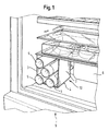
- Fig. 1 shows a first embodiment of a holding device 10 for storing bottles in a refrigerator 9, which comprises a U-shaped bent sheet metal with a base part 1 and adjoining the two sides of the base part 1 at right angles side parts 2 and 3.
- the radii of the transitions 4 between the base part 1 and the side parts 2 and 3 are adapted to the corner radii of the refrigerator interior, so that a space-saving accommodation in the refrigerator 9 is made possible.
- bottles 5, in particular wine bottles can be stacked in the holding device 10 with the neck to the rear.
- the side parts 2 and 3 define, together with the base part 1, an opening plane open to the front, which runs approximately parallel to the refrigerator door (not illustrated) and through which the bottles 5 can be inserted into the holding device 10.
- the side parts 2, 3 are formed as side walls.
- the holding device 10 is shown in the lower left corner of the refrigerator interior, so that the bottle necks protrude into the space next to the compressor 6 in. This achieves a particularly efficient utilization of the available space.
- FIG. 1 At the bottom of the base part 1 of the holding device 10 are in FIG. 1 invisible rubber feet provided. On the one hand, they prevent slippage of the holding device 10 in the refrigerator. At the same time this avoids scratching the inside of the refrigerator.
- Fig. 2 shows a second embodiment of a holding device 10 ', in which the side parts 2, 3 and the base part 1 are provided with recesses 7 for receiving the bottles 5. This will allow even more space-saving storage, this is the Holding device 10 'only for a particular bottle or can size, in the present case wine bottles suitable.
- Fig. 3 shows a cross section through a holding device 10 of Fig. 1 , wherein in this illustration, the rubber feet 11 are visible.
- the transitions 4 between the base part 1 and the side parts 2 and 3 are flattened in this example in order to adapt to the corner radii of the refrigerator interior.
- the opening plane of the in the Fig. 3 - 8 shown holding devices lies in the plane of the paper.
- Fig. 4 shows a cross section through a holding device 10 'according to the second embodiment of the Fig. 2 , In this fixture, five bottles can be stored, one in each of the bulges 7 and one in the middle.
- Fig. 5 shows a holding device 10 in the manner of FIG. 1 in cross section, but which is provided with an insert 8, which comprises several compartments for individual bottles.
- the insert 8 consists in the example shown of two vertical and two horizontal plates, which intersect each other at right angles.
- the insert is adapted to a particular bottle or can size (eg wine bottles, beer bottles, beverage cans).
- the use has honeycomb, ie in cross-section hexagonal, compartments, whereby a particularly space-saving stacking of bottles or cans is possible.
- Different inserts 8 for different bottle sizes can fit in one and the same holding device 10.
- Fig. 6 shows a third embodiment of a holding device 10, which has a slightly V-shaped cross-section, since the side parts 2 and 3 protrude at an angle of approximately 100 ° from the defined by the base part 1 Abstellbene outward.
- the holding device 10 of Fig. 6 also has a ceiling part 12, which connects the free ends of the side parts 2, 3 with each other.
- the ceiling part 12 is preferably integral with the side parts 2, 3rd
- a fourth embodiment of a holding device 10 which has a V-shaped cross section.
- the side parts 2, 3 protrude from a common approach on the base part 1 with an opening angle of about 60 ° above and form between them a receptacle for bottles, cans and other refrigerated goods.
- the base part 1 defines a mounting plane and forms a stable footprint.
- Fig. 8 shows a schematic cross section through a fifth embodiment of a holding device 10, which has a substantially X-shaped cross-section.
- the base part is formed by two legs 1a, 1b, which are directed from a crossing line 13 downwards, while the two side parts 2, 3 are directed from the common crossing line 13 upwards.
- the base part legs 1a, 1b and the side parts 2, 3 each have an angle of approximately 90 ° to each other. Further embodiments are designed such that the opening angle between the side parts 2, 3 and between the two base part legs 1a and 1b is approximately 100 ° - 140 °.
- the side parts 2, 3 may also be arched outwardly to provide a larger receiving space for refrigerated goods.
- the base part legs 1a and the side part 2 and the base part legs 1b and the side part 3 are each formed by a plate, wherein the two plates are preferably inserted crosswise into one another.
Landscapes
- Engineering & Computer Science (AREA)
- Chemical & Material Sciences (AREA)
- Combustion & Propulsion (AREA)
- Physics & Mathematics (AREA)
- Mechanical Engineering (AREA)
- Thermal Sciences (AREA)
- General Engineering & Computer Science (AREA)
- Packages (AREA)
Abstract
Description
- Die vorliegende Erfindung betrifft ein Kältegerät, insbesondere ein Haushaltskältegerät, mit einer Haltevorrichtung zur Lagerung von Flaschen oder Dosen, insbesondere einen Kühlschrank, mit einem derartigen Gestell.
- Zur Lagerung von Flaschen, insbesondere Weinflaschen, in Kühlschränken sind verschiedene Möglichkeiten bekannt. Eine Möglichkeit besteht darin, die Flaschen in einem Abstellbehälter in der Kühlschranktür stehend unterzubringen. Ein Nachteil besteht darin, dass hier für verschiedene Nahrungsmittel, die dort untergebracht werden sollen, nur ein begrenzter Raum zur Verfügung steht. Nachteilig ist auch der relativ große Abstand zu den Kühlflächen, sodass eine eventuell gewünschte schnelle Kühlung der Flaschen nicht erreicht wird. In speziellen Weinkühlschränken verwendet man üblicherweise Ablageböden. Für normale Kühlschränke sind diese wegen ihres großen Platzbedarfs weniger geeignet.
- Der vorliegenden Erfindung liegt die Aufgabe zu Grunde, eine neue Raum sparende Möglichkeit zur Lagerung von Flaschen oder Dosen in einem Kühlschrank zu schaffen, die noch dazu eine effiziente Kühlung der Flaschen ermöglicht.
- Zur Lösung dieser Aufgabe schlägt die Erfindung ein Kältegerät, insbesondere ein Haushaltskältegerät, vor, das mit einer Haltevorrichtung zur Lagerung von Flaschen oder Dosen gemäß Anspruch 1 ausgestattet ist. Das Kältegerät ist vorzugsweise ein Kühlschrank oder ein Tiefkühlschrank.
- Die Haltevorrichtung des erfindungsgemäßen Kältegerätes umfasst ein als Boden dienendes Basisteil und zwei sich an den beiden Seiten des Basisteils anschließende, vom Basisteil nach oben weggerichtete, Seitenteile, die zusammen mit dem Basisteil eine Öffnungsebene bilden. Die Öffnungsebene ist vorzugsweise im Wesentlichen quer zum Basisteil und den beiden Seitenteilen ausgerichtet. Durch die Öffnungsebene können Flaschen, Dosen oder anderes Kühlgut in die Haltevorrichtung eingelegt werden, welche insbesondere zur liegenden Lagerung von Flaschen oder Dosen geeignet ist. Die Flaschen oder Dosen werden dabei auf dem Basisteil gestapelt und durch die Seitenteile am Wegrollen gehindert. Die Haltevorrichtung ist nach vorne zu der Öffnungsebene hin offen, vorzugsweise ist sie auch nach oben und hinten offen, kann jedoch insbesondere nach oben auch geschlossen sein.
- Das Basisteil und die Seitenteile sind vorzugsweise durch plattenartige Komponenten, insbesondere Blechstücke, gebildet. Die plattenartigen Teile sind vorzugsweise ca. 0,2mm bis 3mm dich und können aus Metallblech (z.B. Aluminium oder Eisen), Kunststoff, Glas oder Keramik gefertigt sein. Um Material zu sparen, können das Basisteil und die Seitenteile mit Löchern oder Schlitzen versehen sein. Alternativ kann die Haltevorrichtung auch aus ggfs. verstärkter Pappe hergestellt sein.
- Vorteilhafterweise passt die Haltevorrichtung genau in eine untere Ecke des Kühlschranks. Besonders bevorzugt sind die Übergänge zwischen Basisteil und Seitenteilen an die Form des Kühlschrankinnenraums angepasst. Dies kann insbesondere dadurch erreicht werden, dass die Eckradien an den Übergängen zwischen Basisteil und Seitenteilen entsprechend den Eckradien des Kühlschrankinnenraums ausgebildet sind. Die Haltevorrichtung kann dann Platz sparend direkt neben dem Kühlschrankkompressor angeordnet werden, wo es besonders wirksam gekühlt wird. Die Haltevorrichtung kann dabei so ausgebildet werden, dass sie mit einer Gemüseschale ausgetauscht werden kann. Darüber hinaus können auch das Basisteil und die Seitenteile an die Form des Kühlschrankinnenbehälters angepasst sein. Die Abmessungen des Basisteils und/oder der Seitenteile sind vorzugsweise an die Größe des Kühlschrankinnenbehälters, insbesondere an den Platz neben dem Kompressor, angepasst.
- Vorzugsweise weist die durch das Basisteil und die Seitenteile gebildete Haltevorrichtung einen im Wesentlichen U-förmigen oder im Wesentlichen V-förmigen oder im Wesentlichen X-förmigen Querschnitt auf. Ist die Haltevorrichtung im Querschnitt U-förmig oder V-förmig, so ist sie bevorzugt aus einem plattenartigen Halbzeug geformt. Dabei bilden die beiden Seitenteile die Schenkel des U und das Basisteil das die Schenkel verbindende Zwischenstück. Besonders bevorzugt ist die Haltevorrichtung aus einem zumindest im Wesentlichen U-förmig oder V-förmig gebogenen Blech, insbesondere Metallblech, hergestellt. Bei einem U-förmigen Querschnitt. Bei allen Ausführungsformen haben Basisteil und Seitenteile vorzugsweise eine konstante Tiefe und/oder Materialstärke. Bei einer im Wesentlichen V-förmigen Haltevorrichtung weisen die beiden Seitenteile nach oben und voneinander weg. Um die Haltevorrichtung zu stabilisieren, ragt das Basisteil bei der V-förmigen Ausführungsform vorzugsweise zu den Seiten über die Ansätze der Seitenteile nach außen und bildet somit eine stabile Standfläche.
- Bei einem X-förmigen Querschnitt hat das Basisteil zwei Schenkel, die von dem Ansatzpunkt der beiden Seitenteile nach unten und zu den Seiten abstehen. Eine Haltevorrichtung mit X-förmigem Querschnitt wird vorzugsweise durch Ineinanderschieben von zwei jeweils bis zur Mitte geschlitzten, gleichgroßen, rechteckigen Plattenteilen gebildet.
- Die Haltevorrichtung ist vorzugsweise mit einem Deckenteil versehen, das die freien Enden der Seitenteile miteinander verbindet. Das Deckenteil kann abnehmbar sein oder einstückig mit einem oder beiden der beiden Seitenteile ausgebildet sein.
- Das Basisteil bildet vorzugsweise eine Aufstellebene für die Haltevorrichtung, welche somit auf dem Basisteil ruht. Vorzugsweise bildet das Basisteil eine stabile Standfläche für die Haltevorrichtung.
- Ferner erstrecken sich die beiden Seitenteile der im Querschnitt U-förmigen Haltevorrichtung vorzugsweise im Wesentlichen rechtwinklig von der Aufstellebene. Alternativ können sich die beiden Seitenteile im Querschnitt auch in einem Winkel von 60° bis 130° von der Abstellebene erstrecken, wobei eine symmetrische Anordnung der Seitenteile bevorzugt ist.
- Gemäß einer vorteilhaften Ausbildung der Erfindung werden an der Unterseite des Basisteils Gummifüße vorgesehen, um ein Verrutschen und das Verkratzen des Kühlschrankinnenbehälters zu verhindern.
- Gemäß einer bevorzugten Ausführungsform können in den Seitenteilen Ausbuchtungen zur Aufnahme von Flaschen vorgesehen sein. Diese sind vorzugsweise im Querschnitt kreissegmentförmig, wobei der Kreisradius etwa dem Außenradius einer Wein- oder Bierflasche entspricht. Der Querschnitt der Haltevorrichtung ist vorzugsweise über deren gesamte Tiefe gleich.
- Gemäß einer weiteren bevorzugten Ausführungsform weist die Vorrichtung einen Einsatz auf, welcher mehrere Fächer für einzelne Flaschen umfasst. Ein derartiger Einsatz kann im Querschnitt kreuzförmig oder doppelkreuzförmig gestaltet sein.
- Die Flaschen können mit dem Hals nach hinten in der Haltevorrichtung gestapelt werden. Bei der Lagerung von Dosen können ggf. jeweils zwei Dosen hintereinander gestapelt werden.
- Durch die Erfindung wird eine mit geringen Kosten herstellbare Haltevorrichtung geschaffen, das es gestattet, Flaschen oder Dosen, insbesondere Weinflaschen, Platz sparend und mit effektiver Kühlung in einem Kühlschrank unterzubringen. Ein weiterer Vorteil besteht in der Möglichkeit, die Haltevorrichtung einfach zu reinigen, ggf. sogar im Geschirrspüler.
- Im Folgenden werden Ausführungsbeispiele der Erfindung an Hand der Figuren erläutert. In den Figuren zeigen:
- Fig. 1
- eine perspektivische Ansicht einer Haltevorrichtung zur Lagerung von Flaschen in einem Kühlschrank gemäß einer ersten Ausführungsform der Erfindung;
- Fig. 2
- eine perspektivische Ansicht einer Haltevorrichtung zur Lagerung von Flaschen in einem Kühlschrank gemäß einer zweiten Ausführungsform der Erfindung;
- Fig. 3
- einen Querschnitt durch eine Haltevorrichtung zur Lagerung von Flaschen gemäß der ersten Ausführungsform der Erfindung;
- Fig. 4
- einen Querschnitt durch eine Haltevorrichtung zur Lagerung von Flaschen gemäß der zweiten Ausführungsform der Erfindung;
- Fig. 5
- einen Querschnitt durch eine Haltevorrichtung zur Lagerung von Flaschen mit Einsatzteil;
- Fig. 6
- einen Querschnitt durch eine Haltevorrichtung zur Lagerung von Flaschen gemäß einer dritten Ausführungsform der Erfindung;
- Fig. 7
- einen Querschnitt durch eine Haltevorrichtung zur Lagerung von Flaschen gemäß einer vierten Ausführungsform der Erfindung;
- Fig. 8
- einen Querschnitt durch eine Haltevorrichtung zur Lagerung von Flaschen gemäß einer fünften Ausführungsform der Erfindung.
-
Fig. 1 zeigt eine erste Ausführungsform einer Haltevorrichtung 10 zur Lagerung von Flaschen in einem Kühlschrank 9, welches ein U-förmig gebogenes Blech mit einem Basisteil 1 und sich an die beiden Seiten des Basisteils 1 unter rechten Winkeln anschließenden Seitenteilen 2 und 3 umfasst. Die Radien der Übergänge 4 zwischen Basisteil 1 und den Seitenteilen 2 und 3 sind den Eckradien des Kühlschrankinnenraums angepasst, sodass eine Platz sparende Unterbringung im Kühlschrank 9 ermöglicht wird. Wie dargestellt können Flaschen 5, insbesondere Weinflaschen, in der Haltevorrichtung 10 mit dem Hals nach hinten gestapelt werden. Die Seitenteilen 2 und 3 definieren zusammen mit dem Basisteil 1 eine nach vorne offene Öffnungsebene, die ungefähr parallel zur nicht dargstellten Kühlschranktür verläuft und durch die die Flaschen 5 in die Haltevorrichtung 10 eingesetzt werden können. Vorzugsweise sind die Seitenteile 2, 3 als Seitenwände ausgebildet. - Die Haltevorrichtung 10 ist in der unteren linken Ecke des Kühlschrankinnenraums dargestellt, so dass die Flaschenhälse in den Raum neben dem Kompressor 6 hinein ragen. Dadurch wird eine besonders effiziente Ausnutzung des vorhandenen Raums erreicht.
- An der Unterseite des Basisteils 1 der Haltevorrichtung 10 sind in
Figur 1 nicht sichtbare Gummifüße vorgesehen. Sie verhindern einerseits ein Verrutschen der Haltevorrichtung 10 im Kühlschrank. Gleichzeitig vermeidet man hierdurch ein Verkratzen des Kühlschrankinnenbehälters. -
Fig. 2 zeigt eine zweite Ausführungsform einer Haltevorrichtung 10', in der die Seitenteile 2, 3 sowie das Basisteil 1 mit Ausbuchtungen 7 zur Aufnahme der Flaschen 5 versehen sind. Dadurch wird eine noch Platz sparendere Lagerung möglich, dafür ist die Haltevorrichtung 10' nur für eine bestimmte Flaschen- oder Dosengröße, im vorliegenden Fall Weinflaschen, geeignet. -
Fig. 3 zeigt einen Querschnitt durch eine Haltevorrichtung 10 derFig. 1 , wobei in dieser Darstellung auch die Gummifüße 11 sichtbar sind. Die Übergänge 4 zwischen Basisteil 1 und den Seitenteilen 2 und 3 sind in diesem Beispiel abgeflacht, um sich an die Eckradien des Kühlschrankinnenraums anzupassen. Die Öffnungsebene der in denFig. 3 - 8 dargestellten Haltevorrichtungen liegt in der Papierebene. -
Fig. 4 zeigt einen Querschnitt durch eine Haltevorrichtung 10' gemäß der zweiten Ausführungsform derFig. 2 . In dieser Haltevorrichtung können fünf Flaschen gelagert werden, eine in jeder der Ausbuchtungen 7 und eine in der Mitte. -
Fig. 5 zeigt eine Haltevorrichtung 10 nach Art derFigur 1 im Querschnitt, welches jedoch mit einem Einsatz 8 versehen ist, welcher mehrere Fächer für einzelne Flaschen umfasst. Der Einsatz 8 besteht im dargestellten Beispiel aus zwei senkrechten und zwei waagerechten Blechen, die einander jeweils im rechten Winkel kreuzen. Vorteilhafterweise ist der Einsatz an eine bestimmte Flaschen- oder Dosengröße (z.B. Weinflaschen, Bierflaschen, Getränkedosen) angepasst. Gemäß einer nicht dargestellten Alternative weist der Einsatz wabenförmige, d.h. im Querschnitt sechseckige, Fächer auf, wodurch eine besonders Platz sparende Stapelung von Flaschen oder Dosen ermöglicht wird. Es können verschiedene Einsätze 8 für verschiedene Flaschengrößen in ein und dieselbe Haltevorrichtung 10 passen. -
Fig. 6 zeigt eine dritte Ausführungsform einer Haltevorrichtung 10, welche einen leicht V-förmigen Querschnitt aufweist, da die Seitenteile 2 und 3 in einem Winkel von ca. 100° von der durch das Basisteil 1 definierten Abstellebene nach außen wegstehen. Die Haltevorrichtung 10 derFig. 6 weist ferner ein Deckenteil 12 auf, welches die freien Enden der Seitenteile 2, 3 miteinander verbindet. Das Deckenteil 12 ist vorzugsweise einstückig mit den Seitenteilen 2, 3. - In
Fig. 7 ist eine vierte Ausführungsform einer Haltevorrichtung 10 dargestellt, welche einen V-förmigen Querschnitt aufweist. Die Seitenteile 2, 3 ragen von einem gemeinsamen Ansatz auf dem Basisteil 1 mit einem Öffnungswinkel von ca. 60° nach oben und bilden zwischen sich eine Aufnahme für Flaschen, Dosen und anderes Kühlgut. Das Basisteil 1 definiert eine Aufstellebene und bildet eine stabile Standfläche. -
Fig. 8 zeigt einen schematischen Querschnitt durch eine fünfte Ausführungsform einer Haltevorrichtung 10, welche einen im Wesentlichen X-förmigen Querschnitt aufweist. Hier ist das Basisteil durch zwei Schenkel 1a, 1 b ausgebildet, die von einer Kreuzungslinie 13 nach unten gerichtet sind, während die beiden Seitenteile 2, 3 von der gemeinsamen Kreuzungslinie 13 nach oben gerichtet sind. Im dargestellten Beispiel weisen die Basisteil-Schenkel 1a, 1b und die Seitenteile 2, 3 jeweils einen Winkel von ca. 90° zueinander auf. Weitere Ausführungsformen sind so ausgebildet, dass der Öffnungswinkel zwischen den Seitenteilen 2, 3 sowie zwischen den beiden Basisteil-Schenkeln 1a und 1b ca. 100° - 140° beträgt. Die Seitenteile 2, 3 können ferner nach außen gewölbt sein, um einen größeren Aufnahmeraum für Kühlgut bereitzustellen. Vorzugsweise werden der Basisteil-Schenkel 1a und das Seitenteil 2 sowie der Basisteil-Schenkel 1b und das Seitenteil 3 jeweils durch eine Platte gebildet, wobei die beiden Platten bevorzugt kreuzförmig ineinander gesteckt sind.
Claims (11)
- Kältegerät (9), insbesondere Haushaltskältegerät, mit einer Haltevorrichtung (10, 10') zur Lagerung von Flaschen (5) oder Dosen, umfassend ein als Boden dienendes Basisteil (1) und zwei sich an den beiden Seiten des Basisteils (1) anschließenden, vom Basisteil (1) nach oben weggerichteten Seitenteilen (2,3).
- Kältegerät (9) nach Anspruch 1, dadurch gekennzeichnet, dass das Basisteil (1) und die Seitenteile (2,3) und/oder die Übergänge (4) zwischen Basisteil (1) und Seitenteilen (2,3) an die Form des Kühlschrankinnenraums angepasst sind.
- Kältegerät (9) nach Anspruch 1 oder 2, dadurch gekennzeichnet dass die Eckradien an den Übergängen (4) zwischen Basisteil (1) und Seitenteilen (2,3) entsprechend den Eckradien des Kühlschrankinnenraums ausgebildet sind.
- Kältegerät (9) nach einem der vorherigen Ansprüche, dadurch gekennzeichnet, dass die durch das Basisteil (1) und die Seitenteile (2, 3) gebildete Haltevorrichtung (10, 10') einen im Wesentlichen U-förmigen oder im Wesentlichen V-förmigen oder im Wesentlichen X-förmigen Querschnitt aufweist.
- Kältegerät nach Anspruch 4, dadurch gekennzeichnet, dass die im Querschnitt U-förmige oder V-förmige Haltevorrichtung (10, 10') aus einem plattenartigen Halbzeug geformt ist.
- Kältegerät nach einem der Ansprüche 1 bis 5, dadurch gekennzeichnet, dass die Haltevorrichtung (10, 10') mit einem Deckenteil (12) versehen ist, das die freien Enden der Seitenteile (2, 3) miteinander verbindet.
- Kältegerät nach einem der Ansprüche 1 bis 6, dadurch gekennzeichnet, dass das Basisteil (1) eine Aufstellebene für die Haltevorrichtung (10, 10') definiert.
- Kältegerät nach Anspruch 7, dadurch gekennzeichnet, dass die beiden Seitenteile (2,3) der im Querschnitt U-förmigen Haltevorrichtung (10, 10') sich in Wesentlichen rechtwinklig von der Aufstellebene erstrecken.
- Kältegerät nach einem der vorherigen Ansprüche, dadurch gekennzeichnet, dass das Basisteil (1) als Aufstellebene dient und dass an der Unterseite des Basisteils (1) Gummifüße angeordnet sind.
- Kältegerät nach einem der vorherigen Ansprüche, dadurch gekennzeichnet, dass dass in den Seitenteilen (2,3) der Haltevorrichtung (10') Ausbuchtungen (7) zur Aufnahme von Flaschen vorgesehen sind.
- Kältegerät nach einem der vorherigen Ansprüche, dadurch gekennzeichnet, dass die Haltevorrichtung (10) einen Einsatz (8) aufweist, welcher mehrere Fächer für einzelne Flaschen (5) umfasst.
Priority Applications (1)
| Application Number | Priority Date | Filing Date | Title |
|---|---|---|---|
| PL09100188T PL2107326T3 (pl) | 2008-04-04 | 2009-03-17 | Urządzenie chłodzące z urządzeniem mocującym do przechowywania butelek |
Applications Claiming Priority (1)
| Application Number | Priority Date | Filing Date | Title |
|---|---|---|---|
| DE202008004770U DE202008004770U1 (de) | 2008-04-04 | 2008-04-04 | Kältegerät mit einer Haltevorrichtung zur Lagerung von Flaschen |
Publications (2)
| Publication Number | Publication Date |
|---|---|
| EP2107326A1 true EP2107326A1 (de) | 2009-10-07 |
| EP2107326B1 EP2107326B1 (de) | 2020-09-16 |
Family
ID=39531284
Family Applications (1)
| Application Number | Title | Priority Date | Filing Date |
|---|---|---|---|
| EP09100188.3A Active EP2107326B1 (de) | 2008-04-04 | 2009-03-17 | Kältegerät mit einer Haltevorrichtung zur Lagerung von Flaschen |
Country Status (3)
| Country | Link |
|---|---|
| EP (1) | EP2107326B1 (de) |
| DE (1) | DE202008004770U1 (de) |
| PL (1) | PL2107326T3 (de) |
Citations (4)
| Publication number | Priority date | Publication date | Assignee | Title |
|---|---|---|---|---|
| US5819937A (en) | 1997-05-16 | 1998-10-13 | Walker; Kimberly K. | Bottle organizer |
| EP1426716A1 (de) | 2002-12-05 | 2004-06-09 | SMEG S.p.A. | Kühlschrank |
| WO2005057109A1 (en) | 2003-12-09 | 2005-06-23 | Arcelik Anonim Sirketi | A cooling device |
| WO2006090342A1 (en) | 2005-02-28 | 2006-08-31 | Arcelik Anonim Sirketi | A cooling device |
-
2008
- 2008-04-04 DE DE202008004770U patent/DE202008004770U1/de not_active Expired - Lifetime
-
2009
- 2009-03-17 PL PL09100188T patent/PL2107326T3/pl unknown
- 2009-03-17 EP EP09100188.3A patent/EP2107326B1/de active Active
Patent Citations (4)
| Publication number | Priority date | Publication date | Assignee | Title |
|---|---|---|---|---|
| US5819937A (en) | 1997-05-16 | 1998-10-13 | Walker; Kimberly K. | Bottle organizer |
| EP1426716A1 (de) | 2002-12-05 | 2004-06-09 | SMEG S.p.A. | Kühlschrank |
| WO2005057109A1 (en) | 2003-12-09 | 2005-06-23 | Arcelik Anonim Sirketi | A cooling device |
| WO2006090342A1 (en) | 2005-02-28 | 2006-08-31 | Arcelik Anonim Sirketi | A cooling device |
Also Published As
| Publication number | Publication date |
|---|---|
| EP2107326B1 (de) | 2020-09-16 |
| PL2107326T3 (pl) | 2021-04-06 |
| DE202008004770U1 (de) | 2008-06-19 |
Similar Documents
| Publication | Publication Date | Title |
|---|---|---|
| EP2606301B1 (de) | Kältegerät mit ablage für kühlgut | |
| EP2531791B1 (de) | Trennelement für ein haushaltskältegerät | |
| WO1999026032A1 (de) | Kühlgerät | |
| DE10121804A1 (de) | Fachteiler | |
| WO2011124427A1 (de) | Fachboden für ein kältegerät | |
| EP1882140B1 (de) | Innenbehälter für ein kältegerät | |
| WO2012045577A2 (de) | Kältegerät mit einem fachboden | |
| EP2531792B1 (de) | Flaschenablage für ein kältegerät | |
| DE102011078316A1 (de) | Kältegerät mit einer am Fachboden verstellbar gelagerten Trennvorrichtung | |
| WO2009127576A1 (de) | Kühlgutabstellfach | |
| EP2107326B1 (de) | Kältegerät mit einer Haltevorrichtung zur Lagerung von Flaschen | |
| EP2059752A1 (de) | Kältegerät und auszugkasten dafür | |
| EP1660827B1 (de) | Ablagevorrichtung für ein kältegerät | |
| EP1434968B1 (de) | Kältegerät und türabstellfach dafür | |
| DE102017216293A1 (de) | Türabsteller für ein Kältegerät | |
| WO2007090696A2 (de) | Kältegerät und fachboden dafür | |
| DE202005018724U1 (de) | Haushaltsgerät mit Fachboden | |
| EP2618084B1 (de) | Ablagevorrichtung aufweisend eine Klappenbefestigungsvorrichtung und Haushaltskältegerät mit einer solchen Ablagevorrichtung | |
| DE102021103103A1 (de) | Kühlregal mit Bodenwanne | |
| DE102013223162A1 (de) | Flaschenträgergestell | |
| DE202004020074U1 (de) | Tür für insbesondere einen Kühlschrank | |
| DE202011106498U1 (de) | Kältegerät mit Flaschenabsteller und Auszugfach | |
| DE102008019413A1 (de) | Kühlgutabstellfach | |
| DE202015005046U1 (de) | Kühlvorrichtung für Getränkeflaschen und dergleichen | |
| DE10339928A1 (de) | Kältegerät mit Schubladen |
Legal Events
| Date | Code | Title | Description |
|---|---|---|---|
| PUAI | Public reference made under article 153(3) epc to a published international application that has entered the european phase |
Free format text: ORIGINAL CODE: 0009012 |
|
| AK | Designated contracting states |
Kind code of ref document: A1 Designated state(s): AT BE BG CH CY CZ DE DK EE ES FI FR GB GR HR HU IE IS IT LI LT LU LV MC MK MT NL NO PL PT RO SE SI SK TR |
|
| AX | Request for extension of the european patent |
Extension state: AL BA RS |
|
| 17P | Request for examination filed |
Effective date: 20100407 |
|
| 17Q | First examination report despatched |
Effective date: 20100512 |
|
| AKX | Designation fees paid |
Designated state(s): AT BE BG CH CY CZ DE DK EE ES FI FR GB GR HR HU IE IS IT LI LT LU LV MC MK MT NL NO PL PT RO SE SI SK TR |
|
| RAP1 | Party data changed (applicant data changed or rights of an application transferred) |
Owner name: BSH HAUSGERAETE GMBH |
|
| STAA | Information on the status of an ep patent application or granted ep patent |
Free format text: STATUS: EXAMINATION IS IN PROGRESS |
|
| GRAP | Despatch of communication of intention to grant a patent |
Free format text: ORIGINAL CODE: EPIDOSNIGR1 |
|
| STAA | Information on the status of an ep patent application or granted ep patent |
Free format text: STATUS: GRANT OF PATENT IS INTENDED |
|
| INTG | Intention to grant announced |
Effective date: 20200508 |
|
| GRAS | Grant fee paid |
Free format text: ORIGINAL CODE: EPIDOSNIGR3 |
|
| GRAA | (expected) grant |
Free format text: ORIGINAL CODE: 0009210 |
|
| STAA | Information on the status of an ep patent application or granted ep patent |
Free format text: STATUS: THE PATENT HAS BEEN GRANTED |
|
| AK | Designated contracting states |
Kind code of ref document: B1 Designated state(s): AT BE BG CH CY CZ DE DK EE ES FI FR GB GR HR HU IE IS IT LI LT LU LV MC MK MT NL NO PL PT RO SE SI SK TR |
|
| REG | Reference to a national code |
Ref country code: GB Ref legal event code: FG4D Free format text: NOT ENGLISH |
|
| REG | Reference to a national code |
Ref country code: CH Ref legal event code: EP |
|
| REG | Reference to a national code |
Ref country code: DE Ref legal event code: R096 Ref document number: 502009016271 Country of ref document: DE |
|
| REG | Reference to a national code |
Ref country code: IE Ref legal event code: FG4D Free format text: LANGUAGE OF EP DOCUMENT: GERMAN |
|
| REG | Reference to a national code |
Ref country code: AT Ref legal event code: REF Ref document number: 1314527 Country of ref document: AT Kind code of ref document: T Effective date: 20201015 |
|
| PG25 | Lapsed in a contracting state [announced via postgrant information from national office to epo] |
Ref country code: FI Free format text: LAPSE BECAUSE OF FAILURE TO SUBMIT A TRANSLATION OF THE DESCRIPTION OR TO PAY THE FEE WITHIN THE PRESCRIBED TIME-LIMIT Effective date: 20200916 Ref country code: NO Free format text: LAPSE BECAUSE OF FAILURE TO SUBMIT A TRANSLATION OF THE DESCRIPTION OR TO PAY THE FEE WITHIN THE PRESCRIBED TIME-LIMIT Effective date: 20201216 Ref country code: GR Free format text: LAPSE BECAUSE OF FAILURE TO SUBMIT A TRANSLATION OF THE DESCRIPTION OR TO PAY THE FEE WITHIN THE PRESCRIBED TIME-LIMIT Effective date: 20201217 Ref country code: SE Free format text: LAPSE BECAUSE OF FAILURE TO SUBMIT A TRANSLATION OF THE DESCRIPTION OR TO PAY THE FEE WITHIN THE PRESCRIBED TIME-LIMIT Effective date: 20200916 Ref country code: BG Free format text: LAPSE BECAUSE OF FAILURE TO SUBMIT A TRANSLATION OF THE DESCRIPTION OR TO PAY THE FEE WITHIN THE PRESCRIBED TIME-LIMIT Effective date: 20201216 Ref country code: HR Free format text: LAPSE BECAUSE OF FAILURE TO SUBMIT A TRANSLATION OF THE DESCRIPTION OR TO PAY THE FEE WITHIN THE PRESCRIBED TIME-LIMIT Effective date: 20200916 |
|
| REG | Reference to a national code |
Ref country code: NL Ref legal event code: MP Effective date: 20200916 |
|
| PG25 | Lapsed in a contracting state [announced via postgrant information from national office to epo] |
Ref country code: LV Free format text: LAPSE BECAUSE OF FAILURE TO SUBMIT A TRANSLATION OF THE DESCRIPTION OR TO PAY THE FEE WITHIN THE PRESCRIBED TIME-LIMIT Effective date: 20200916 |
|
| REG | Reference to a national code |
Ref country code: LT Ref legal event code: MG4D |
|
| PG25 | Lapsed in a contracting state [announced via postgrant information from national office to epo] |
Ref country code: EE Free format text: LAPSE BECAUSE OF FAILURE TO SUBMIT A TRANSLATION OF THE DESCRIPTION OR TO PAY THE FEE WITHIN THE PRESCRIBED TIME-LIMIT Effective date: 20200916 Ref country code: CZ Free format text: LAPSE BECAUSE OF FAILURE TO SUBMIT A TRANSLATION OF THE DESCRIPTION OR TO PAY THE FEE WITHIN THE PRESCRIBED TIME-LIMIT Effective date: 20200916 Ref country code: RO Free format text: LAPSE BECAUSE OF FAILURE TO SUBMIT A TRANSLATION OF THE DESCRIPTION OR TO PAY THE FEE WITHIN THE PRESCRIBED TIME-LIMIT Effective date: 20200916 Ref country code: LT Free format text: LAPSE BECAUSE OF FAILURE TO SUBMIT A TRANSLATION OF THE DESCRIPTION OR TO PAY THE FEE WITHIN THE PRESCRIBED TIME-LIMIT Effective date: 20200916 Ref country code: NL Free format text: LAPSE BECAUSE OF FAILURE TO SUBMIT A TRANSLATION OF THE DESCRIPTION OR TO PAY THE FEE WITHIN THE PRESCRIBED TIME-LIMIT Effective date: 20200916 Ref country code: PT Free format text: LAPSE BECAUSE OF FAILURE TO SUBMIT A TRANSLATION OF THE DESCRIPTION OR TO PAY THE FEE WITHIN THE PRESCRIBED TIME-LIMIT Effective date: 20210118 |
|
| PG25 | Lapsed in a contracting state [announced via postgrant information from national office to epo] |
Ref country code: PL Free format text: LAPSE BECAUSE OF FAILURE TO SUBMIT A TRANSLATION OF THE DESCRIPTION OR TO PAY THE FEE WITHIN THE PRESCRIBED TIME-LIMIT Effective date: 20200916 Ref country code: IS Free format text: LAPSE BECAUSE OF FAILURE TO SUBMIT A TRANSLATION OF THE DESCRIPTION OR TO PAY THE FEE WITHIN THE PRESCRIBED TIME-LIMIT Effective date: 20210116 Ref country code: ES Free format text: LAPSE BECAUSE OF FAILURE TO SUBMIT A TRANSLATION OF THE DESCRIPTION OR TO PAY THE FEE WITHIN THE PRESCRIBED TIME-LIMIT Effective date: 20200916 |
|
| REG | Reference to a national code |
Ref country code: DE Ref legal event code: R097 Ref document number: 502009016271 Country of ref document: DE |
|
| PG25 | Lapsed in a contracting state [announced via postgrant information from national office to epo] |
Ref country code: SK Free format text: LAPSE BECAUSE OF FAILURE TO SUBMIT A TRANSLATION OF THE DESCRIPTION OR TO PAY THE FEE WITHIN THE PRESCRIBED TIME-LIMIT Effective date: 20200916 |
|
| PLBE | No opposition filed within time limit |
Free format text: ORIGINAL CODE: 0009261 |
|
| STAA | Information on the status of an ep patent application or granted ep patent |
Free format text: STATUS: NO OPPOSITION FILED WITHIN TIME LIMIT |
|
| 26N | No opposition filed |
Effective date: 20210617 |
|
| PG25 | Lapsed in a contracting state [announced via postgrant information from national office to epo] |
Ref country code: SI Free format text: LAPSE BECAUSE OF FAILURE TO SUBMIT A TRANSLATION OF THE DESCRIPTION OR TO PAY THE FEE WITHIN THE PRESCRIBED TIME-LIMIT Effective date: 20200916 Ref country code: DK Free format text: LAPSE BECAUSE OF FAILURE TO SUBMIT A TRANSLATION OF THE DESCRIPTION OR TO PAY THE FEE WITHIN THE PRESCRIBED TIME-LIMIT Effective date: 20200916 |
|
| PG25 | Lapsed in a contracting state [announced via postgrant information from national office to epo] |
Ref country code: MC Free format text: LAPSE BECAUSE OF FAILURE TO SUBMIT A TRANSLATION OF THE DESCRIPTION OR TO PAY THE FEE WITHIN THE PRESCRIBED TIME-LIMIT Effective date: 20200916 Ref country code: IT Free format text: LAPSE BECAUSE OF FAILURE TO SUBMIT A TRANSLATION OF THE DESCRIPTION OR TO PAY THE FEE WITHIN THE PRESCRIBED TIME-LIMIT Effective date: 20200916 |
|
| REG | Reference to a national code |
Ref country code: CH Ref legal event code: PL |
|
| GBPC | Gb: european patent ceased through non-payment of renewal fee |
Effective date: 20210317 |
|
| REG | Reference to a national code |
Ref country code: BE Ref legal event code: MM Effective date: 20210331 |
|
| PG25 | Lapsed in a contracting state [announced via postgrant information from national office to epo] |
Ref country code: LI Free format text: LAPSE BECAUSE OF NON-PAYMENT OF DUE FEES Effective date: 20210331 Ref country code: LU Free format text: LAPSE BECAUSE OF NON-PAYMENT OF DUE FEES Effective date: 20210317 Ref country code: CH Free format text: LAPSE BECAUSE OF NON-PAYMENT OF DUE FEES Effective date: 20210331 Ref country code: IE Free format text: LAPSE BECAUSE OF NON-PAYMENT OF DUE FEES Effective date: 20210317 Ref country code: GB Free format text: LAPSE BECAUSE OF NON-PAYMENT OF DUE FEES Effective date: 20210317 Ref country code: FR Free format text: LAPSE BECAUSE OF NON-PAYMENT OF DUE FEES Effective date: 20210331 |
|
| REG | Reference to a national code |
Ref country code: AT Ref legal event code: MM01 Ref document number: 1314527 Country of ref document: AT Kind code of ref document: T Effective date: 20210317 |
|
| PG25 | Lapsed in a contracting state [announced via postgrant information from national office to epo] |
Ref country code: BE Free format text: LAPSE BECAUSE OF NON-PAYMENT OF DUE FEES Effective date: 20210331 |
|
| PG25 | Lapsed in a contracting state [announced via postgrant information from national office to epo] |
Ref country code: AT Free format text: LAPSE BECAUSE OF NON-PAYMENT OF DUE FEES Effective date: 20210317 |
|
| REG | Reference to a national code |
Ref country code: DE Ref legal event code: R084 Ref document number: 502009016271 Country of ref document: DE |
|
| PG25 | Lapsed in a contracting state [announced via postgrant information from national office to epo] |
Ref country code: HU Free format text: LAPSE BECAUSE OF FAILURE TO SUBMIT A TRANSLATION OF THE DESCRIPTION OR TO PAY THE FEE WITHIN THE PRESCRIBED TIME-LIMIT; INVALID AB INITIO Effective date: 20090317 Ref country code: CY Free format text: LAPSE BECAUSE OF FAILURE TO SUBMIT A TRANSLATION OF THE DESCRIPTION OR TO PAY THE FEE WITHIN THE PRESCRIBED TIME-LIMIT Effective date: 20200916 |
|
| PG25 | Lapsed in a contracting state [announced via postgrant information from national office to epo] |
Ref country code: MK Free format text: LAPSE BECAUSE OF FAILURE TO SUBMIT A TRANSLATION OF THE DESCRIPTION OR TO PAY THE FEE WITHIN THE PRESCRIBED TIME-LIMIT Effective date: 20200916 |
|
| PG25 | Lapsed in a contracting state [announced via postgrant information from national office to epo] |
Ref country code: MT Free format text: LAPSE BECAUSE OF FAILURE TO SUBMIT A TRANSLATION OF THE DESCRIPTION OR TO PAY THE FEE WITHIN THE PRESCRIBED TIME-LIMIT Effective date: 20200916 |
|
| PGFP | Annual fee paid to national office [announced via postgrant information from national office to epo] |
Ref country code: DE Payment date: 20250331 Year of fee payment: 17 |
|
| PGFP | Annual fee paid to national office [announced via postgrant information from national office to epo] |
Ref country code: PL Payment date: 20250306 Year of fee payment: 17 |
|
| PGFP | Annual fee paid to national office [announced via postgrant information from national office to epo] |
Ref country code: TR Payment date: 20250310 Year of fee payment: 17 |