EP2107162A2 - Aufnahme für abgelöstes Material für Straßenbaumaschinen - Google Patents
Aufnahme für abgelöstes Material für Straßenbaumaschinen Download PDFInfo
- Publication number
- EP2107162A2 EP2107162A2 EP20090004407 EP09004407A EP2107162A2 EP 2107162 A2 EP2107162 A2 EP 2107162A2 EP 20090004407 EP20090004407 EP 20090004407 EP 09004407 A EP09004407 A EP 09004407A EP 2107162 A2 EP2107162 A2 EP 2107162A2
- Authority
- EP
- European Patent Office
- Prior art keywords
- tractor
- barrier member
- tab
- configuration
- generally
- Prior art date
- Legal status (The legal status is an assumption and is not a legal conclusion. Google has not performed a legal analysis and makes no representation as to the accuracy of the status listed.)
- Granted
Links
Images






Classifications
-
- E—FIXED CONSTRUCTIONS
- E01—CONSTRUCTION OF ROADS, RAILWAYS, OR BRIDGES
- E01C—CONSTRUCTION OF, OR SURFACES FOR, ROADS, SPORTS GROUNDS, OR THE LIKE; MACHINES OR AUXILIARY TOOLS FOR CONSTRUCTION OR REPAIR
- E01C19/00—Machines, tools or auxiliary devices for preparing or distributing paving materials, for working the placed materials, or for forming, consolidating, or finishing the paving
- E01C19/48—Machines, tools or auxiliary devices for preparing or distributing paving materials, for working the placed materials, or for forming, consolidating, or finishing the paving for laying-down the materials and consolidating them, or finishing the surface, e.g. slip forms therefor, forming kerbs or gutters in a continuous operation in situ
-
- F—MECHANICAL ENGINEERING; LIGHTING; HEATING; WEAPONS; BLASTING
- F16—ENGINEERING ELEMENTS AND UNITS; GENERAL MEASURES FOR PRODUCING AND MAINTAINING EFFECTIVE FUNCTIONING OF MACHINES OR INSTALLATIONS; THERMAL INSULATION IN GENERAL
- F16B—DEVICES FOR FASTENING OR SECURING CONSTRUCTIONAL ELEMENTS OR MACHINE PARTS TOGETHER, e.g. NAILS, BOLTS, CIRCLIPS, CLAMPS, CLIPS OR WEDGES; JOINTS OR JOINTING
- F16B2200/00—Constructional details of connections not covered for in other groups of this subclass
- F16B2200/63—Frangible connections
Definitions
- the present invention relates to paving vehicles, and more particularly to devices for containing a paving material head for use with paving vehicles.
- Paving vehicles or “pavers” are generally known and include a chassis or tractor, a bin or hopper for containing a quantity of paving material (e.g., asphalt), an auger connected with the tractor for spreading material laterally rearwardly thereof, and a screed for leveling paving material connected with the tractor so as to be pulled from the rear end thereof.
- Paving material is typically transferred by means of a conveyor from the bin/hopper mounted on the front of the tractor toward the rear of the tractor, where the material falls from the tractor and deposits onto a base surface (e.g., a roadbed).
- the auger is positioned between the rear end of the tractor and the screed and spreads the paving material falling off of the tractor laterally across front of the screed so as to form a head of material.
- the screed is pulled into the head of material such that a portion of the material head flows under the screed and is leveled, and preferably also compressed, into a mat of material.
- the paving material is formed of an aggregate of material particles of various sizes and there are generally substantial size differences between the larger and smaller particles. Due to these size differences, larger particles, particularly those particles at the top of the material head, tend to fall from the head of material as the paving material is first deposited and then spread by the auger. As such, the head “segregates” or separates into regions of larger particles and smaller particles, with the larger particles tending to accumulate forwardly of the remainder of the head. With such material segregation, the portions of the material head that are leveled tend to have a greater than intended portion of smaller or finer particles, thereby reducing the "strength" of the formed mat.
- the present invention is a material anti-segregation device for a paving vehicle, the vehicle including a tractor, a screed towed from the tractor for forming a mat of paving material on a base surface, and an auger disposed between the tractor and the screed.
- the anti-segregation device comprises a plurality of flexible, elongated barrier members each coupled with the tractor and collectively defining a curtain.
- the curtain is configured to generally retain paving material between the curtain and the screed.
- a plurality of couplers are each configured to connect at least a portion of a separate one of the barrier members with the tractor. Each coupler is also configured to disconnect the at least a portion of the one barrier member from the tractor when tension in the connected member exceeds a predetermined value.
- the present invention is again a material anti-segregation device for a paving vehicle, the paving vehicle being as described above.
- the anti-segregation device comprises a plurality of flexible, elongated barrier members each coupled with the tractor and collectively defining a curtain.
- the curtain is configured to generally retain paving material between the curtain and the screed.
- a plurality of couplers each include a bendable tab configured to engage with a separate one of the barrier members.
- Each tab is configured to deflect between a first configuration, in which the coupler retains the barrier member connected with the tractor, and a second configuration in which the barrier member is removable from the tab so as to disconnect from the tractor.
- the tabs are each further configured to deflect from the first configuration toward the second configuration when tension in the barrier member exceeds a predetermined value.
- the present invention is once again a material anti-segregation device for a paving vehicle, the vehicle being as described above.
- the anti-segregation device comprises a plurality of flexible, elongated barrier members each coupled with the tractor and collectively defining a curtain.
- the curtain is configured to generally retain paving material between the curtain and the screed.
- Each barrier member has a first end connected with the tractor and as second, free end disposeable generally upon the base surface.
- a plurality of couplers are each configured to connect at least a portion of a separate one of the barrier members with the tractor.
- Each coupler is further configured to disconnect the at least a portion of the one barrier member from the tractor when the barrier member second end is held generally stationary with respect to the base surface during movement of the tractor.
- a material anti-segregation device 10 for a paving vehicle 1 includes a tractor 2, a screed 3 towed from the tractor 2 for forming a mat of paving material M on a base surface S, and an auger 4 disposed between the tractor 2 and the screed 4.
- the anti-segregation device 10 basically comprises a plurality of flexible, elongated barrier members 12 and a plurality of couplers 14, preferably one coupler 14 for each barrier member 12.
- Each barrier member 12 is coupled with the tractor 2 and has a first, upper end 12a connected with the tractor 2 and a second, lower "free" end 12b generally disposeable or disposed upon the base surface S.
- the plurality of barrier members 14 collectively define a curtain 11, the curtain 11 being configured to generally retain paving material M between the curtain 11 and the screed 3.
- each coupler 14 is configured to releasably connect at least a portion of a separate one of the barrier members 12 with the tractor 2 and to disconnect the at least a portion of the one barrier member 12 from the tractor 2 when tension T in the connected member 12 exceeds a predetermined value, i.e. T > T P , so as to prevent damage to the tractor 2.
- each barrier member 12 is connected with a portion or component of the tractor 2 (e.g., a frame panel or plate, a flow gate, etc.) and the predetermined tension value T P is less than a failure limit of the connected tractor portion or component.
- the associated coupler 14 is configured to release the barrier member 12 before tensile force T in the member 12 reaches a magnitude at which the connected tractor portion/component would become damaged or fail (i.e., bended, fractured, sheared, etc.).
- each coupler 14 is configured to disconnect from the at least a portion of the one barrier member 12 when the barrier member second end 12b is held generally stationary with respect to the base surface S during movement of the tractor 2. That is, when the second end 12b of one or more barrier members 12 is restrained or "caught” during tractor movement, such as by being “snagged" on a stationary object O as discussed below and depicted in Figs. 9 and 10 , the barrier member second end 12b is held stationary as the barrier first member end 12a continues moving with the tractor 2.
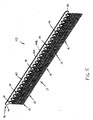
- each coupler 14 is mounted on the tractor 2 and is configured to releasably engage with the upper end 12a of the connected barrier member 12, each coupler 14 being configured to release the connected barrier member 12 separately from each other barrier member 12, as described below. More specifically, the plurality of couplers 14 are attached to and spaced apart laterally along the rear end 2b of the tractor 2, as best shown in Figs. 3 and 4 . Further, the anti-segregation device 10 preferably further comprises a base plate 16 connected with or mounted to the rear end 2a of the tractor 2, each coupler 14 being either mounted to the base plate 16 or preferably integrally formed with the base plate 16, as described in greater detail below.
- each barrier member 12 may alternatively include separate upper and lower portions 13A, 13B, with each coupler 14 being configured to releasably connect the lower portion 13B of a separate one of the barrier members 12 with the barrier member upper portion 13B (not shown).
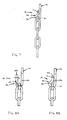
- each coupler 14 is configured to either bend or deflect between a first position or configuration C 1 ( Figs. 9 and 11 ) and a second position/configuration C 2 ( Figs. 10 and 11 ), or alternatively to fracture ( Fig. 12 ), so as to thereby disconnect the connected barrier member 12 from the tractor 2.
- each coupler 14 includes a bendable tab 20 configured to engage with a separate one of the barrier members 12 and to deflect between the first and second configurations C 1 , C 2 . In the first configuration C 1 , the tab 20 retains the barrier member 12 connected with the tractor 2 (see, e.g., Figs.
- each coupler tab 20 is alternatively deflectable toward the first configuration C 1 to connect one of the barrier members 12 to the tractor 2, as shown in Figs. 8A and 8B described in greater detail below.
- each barrier member 12 preferably includes a mounting opening 22 and each tab 20 has an elongated, generally rectangular body 24 with first and second ends 24a, 24b, as shown in Figs. 15 and 16 .
- Each tab body 24 is configured or sized to extend through the opening 22 of the engaged barrier member 12 and to generally form a hook 26 ( Figs. 7 and 8B ) in the tab first configuration C 1 such that the body first end 24a is located at least generally proximal to the body second end 24.
- each coupler tab 20 is configured to generally bend toward a flattened form 27 ( Figs.
- the tab body 24 deflects toward the flattened form in which the body 24 is generally "straight" or non-bended, the body 24 may in fact never reach a state of complete straightness or flatness. That is, the barrier member 14 will likely disengage from the tab 20 prior to the tab body 24 reaching the flattened form, and/or the tab 20 may form a permanent bend or kink (see Fig. 10 ) during the initial process of attaching the barrier member 12 to the tractor 2, as described below.
- the barrier member 12 is displaceable over the tab first end 24a in a direction D 1 generally away from the tab second end 24a when the tab body 24 is disposed in the tab second configuration C 2 , as best shown in Fig. 10 .
- the barrier member 12 is displaceable over the tab first end 24a in a direction D 2 generally toward the tab second end 24a when the tab body 24 is disposed in the tab second configuration C 2 so as to insert the tab body 24 into the barrier member opening 22, as indicated in Fig. 8A .
- the tab body 24 is deflectable from the second configuration C 2 toward the first configuration C 1 , preferably by means of a tool (not shown), when the tab body 24 is disposed or inserted within the barrier member opening 22 so as to connect the barrier member 12 with the tractor 2, as shown in Figs. 8A and 8B and described in further detail below.
- the coupler 14 may be formed in any other appropriate manner that enables the coupler to disconnect the barrier member 12 from the tractor 2 when tension T in the member 12 exceeds a predetermined value T P .
- the coupler 14 may be formed as "split" member 29 that deflects between first and second configurations C 1 , C 2 so as to "open” a gap G in the member 29, to thereby permit the barrier member 12 to disconnect therefrom, when tension T in the barrier member 12 exceeds the predetermined value T P , as shown in Fig. 11 .
- the coupler 14 may be formed with a fractureable or frangible body 31, such as by appropriate material selection and/or sizing, so that the fractured coupler 14 releases the engaged barrier member 12 from connection with the tractor 2 when tension T exceeds the predetermined value T P , as depicted in Fig. 12 .
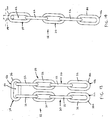
- each barrier member 12 preferably includes at least one and most preferably two chains or chain sections 30, each chain 30 having a plurality of connected links 32. More specifically, each barrier member 12 preferably includes an upper base section 34 providing the member first end 12a and the two chain sections 30 are each attached to the base section 34 and provide the member lower end 12b. Each one of the two chain sections 30 extends generally vertically and generally parallel to the other one of the chain sections 30. Further, each section 30 is separately movable or pivotable in generally longitudinal and generally lateral directions with respect to the base section 34, and thereby also with respect to the tractor 2. Furthermore, each base section 34 preferably provides the mounting opening 22 of each barrier member 12, such that each coupler 14 is engaged/engageable with the base section 34 of a separate one of the barrier members 12 to couple the members 18 to the tractor 2.
- each base section 34 includes or is formed as a single chain link 36, with each chain section 30 being connected with the base section 34 by "interlinking" one link 32 of each chain section 30 with the base section link 36.
- each barrier member 12 is formed as a single chain 38 with opposing ends 38a, 38b, with a central link 36 providing the preferred base section 34 and two remainder sections extending between the central link 36 and each end 38a, 38b providing each barrier chain section 30, as best shown in Fig. 13 .
- each barrier member 12 may be formed in any other appropriate manner.
- each barrier member 12 may be formed with only a single chain section 30, as shown in Fig. 14 .
- each chain section 30 may be formed as a string of pivotally connected plates (not shown) as opposed to links 32.
- the base plate 16 preferably extends generally laterally along the rear end 2a of tractor 2 and the plurality of couplers 14 are spaced apart laterally on the base plate 16. More specifically, the base plate 16 preferably includes a generally flat, generally rectangular elongated body 40 with generally parallel front and rear surfaces 42A, 42B and opposing lateral ends 44. Further, two generally parallel, laterally-extending edges 46 extend between the side ends 44. With such a base plate structure, the tab body 24 of each coupler 14 is preferably formed as a generally flat bar 50 having a first end attached to, and most preferably integrally formed with, one of the plate edges 46 and a second end spaced outwardly from the plate edge 46, as indicated in Fig.
- Each tab bar 50 extends outwardly from the plate edge 46 and generally parallel with the plate surfaces 42A, 42B in an initial position P I , and is deflected from the initial position P I to the tab first configuration C 1 to connect the one of the barrier members 12 with the tractor 2 (see, e.g., Figs. 6 and 7 ).
- the base plate body 40 and the plurality of tab bars 50 are preferably formed as a one-piece construction, most preferably by stamping but may alternatively be cast or machined from a plate.
- the plurality of barrier members 12 are each connected to the base plate 16 by first inserting a tab bar 50 of a separate one of the couplers 14 into the base member opening 22 of the particular member 12. Then, the coupler tab bars 50 are each deflected or bended to the tab first configuration C 1 to releasably retain the barrier members 12 to the base plate 16, as indicated in Figs. 8A and 8B .
- the barrier members 12 are all mounted to the base plate 16, and then the base plate 16 is mounted to the tractor rear end 2a by any appropriate means (e.g., fasteners, mounting brackets, welding, etc.), so as to thereby couple the barrier members 12 with the tractor 2.
- the base plate 16 may first be mounted to the tractor 2 and then the barrier members 12 may be connected with the mounted base plate 16.
- the anti-segregation device 10 preferably includes a base plate 16 and couplers 14 integrally formed with the plate 16, the couplers 14 may alternatively be separately formed and attached to the base plate 16. As another alternative, the anti-segregation device 10 may be constructed without a base plate 16, such that the couplers 14 are individually mounted or connected with the tractor rear end 2a.
Landscapes
- Engineering & Computer Science (AREA)
- Architecture (AREA)
- Civil Engineering (AREA)
- Structural Engineering (AREA)
- Road Repair (AREA)
- Road Paving Machines (AREA)
Applications Claiming Priority (1)
| Application Number | Priority Date | Filing Date | Title |
|---|---|---|---|
| US12/080,144 US8162565B2 (en) | 2008-04-01 | 2008-04-01 | Break-away material retainer for paving vehicles |
Publications (3)
| Publication Number | Publication Date |
|---|---|
| EP2107162A2 true EP2107162A2 (de) | 2009-10-07 |
| EP2107162A3 EP2107162A3 (de) | 2013-12-04 |
| EP2107162B1 EP2107162B1 (de) | 2015-10-21 |
Family
ID=40834312
Family Applications (1)
| Application Number | Title | Priority Date | Filing Date |
|---|---|---|---|
| EP09004407.4A Active EP2107162B1 (de) | 2008-04-01 | 2009-03-26 | Einrichtung für einen Straßenfertiger zum Verhindern der Materialtrennung |
Country Status (2)
| Country | Link |
|---|---|
| US (1) | US8162565B2 (de) |
| EP (1) | EP2107162B1 (de) |
Families Citing this family (6)
| Publication number | Priority date | Publication date | Assignee | Title |
|---|---|---|---|---|
| US9644328B1 (en) * | 2013-08-27 | 2017-05-09 | Gomaco Corporation | Concrete whitetopping system |
| CN103526674B (zh) * | 2013-10-21 | 2015-11-04 | 戴纳派克(中国)压实摊铺设备有限公司 | 一种防离析螺旋分料器及摊铺机 |
| US11554726B2 (en) * | 2020-03-11 | 2023-01-17 | Caterpillar Paving Products Inc. | Machine with sensor units retained by breakaway couplers |
| US11933000B2 (en) * | 2020-10-13 | 2024-03-19 | Samuel C. Patterson | Depth guide for paving machine |
| CN113026482B (zh) * | 2021-03-25 | 2022-07-22 | 浙江交通职业技术学院 | 一种路面摊铺机泵送分料器 |
| EP4617429A1 (de) * | 2024-03-15 | 2025-09-17 | Joseph Vögele AG | Strassenfertiger mit höhenverstellbarem abweisblech |
Citations (1)
| Publication number | Priority date | Publication date | Assignee | Title |
|---|---|---|---|---|
| US6802667B2 (en) | 2000-07-17 | 2004-10-12 | Blaw-Knox Construction Equipment Corporation | Material anti-segregation curtain for a paver |
Family Cites Families (10)
| Publication number | Priority date | Publication date | Assignee | Title |
|---|---|---|---|---|
| US3961493A (en) * | 1975-01-22 | 1976-06-08 | Brown & Root, Inc. | Methods and apparatus for purging liquid from an offshore pipeline and/or scanning a pipeline interior |
| CA1081516A (en) * | 1975-12-31 | 1980-07-15 | Earl F. Cutler | Asphalt pavement recycling apparatus |
| CH635787A5 (de) * | 1979-02-02 | 1983-04-29 | Rud Ketten Rieger & Dietz | Reifenschutzkette. |
| CH642007A5 (de) * | 1979-07-26 | 1984-03-30 | Rud Ketten Rieger & Dietz | Reifenschutzkette. |
| US4708519A (en) * | 1986-04-04 | 1987-11-24 | White Consolidated Industries, Inc. | Asphalt paving machine with liftable, adjustable auger mechanisms |
| US4749304A (en) * | 1986-09-15 | 1988-06-07 | White Consolidated Industries, Inc. | Variable width material distribution system for asphalt pavers and the like |
| US4823366A (en) * | 1987-02-17 | 1989-04-18 | White Consolidated Industries, Inc. | Material conveying equipment with control for paving materials using ultrasonic waves |
| US5232305A (en) * | 1991-05-15 | 1993-08-03 | Caterpillar Paving Products Inc. | Paving material distribution system |
| US5356238A (en) * | 1993-03-10 | 1994-10-18 | Cedarapids, Inc. | Paver with material supply and mat grade and slope quality control apparatus and method |
| US5533828A (en) * | 1994-09-29 | 1996-07-09 | Astec Industries, Inc. | Method and apparatus for discharging paving materials on top of distributing auger |
-
2008
- 2008-04-01 US US12/080,144 patent/US8162565B2/en active Active
-
2009
- 2009-03-26 EP EP09004407.4A patent/EP2107162B1/de active Active
Patent Citations (1)
| Publication number | Priority date | Publication date | Assignee | Title |
|---|---|---|---|---|
| US6802667B2 (en) | 2000-07-17 | 2004-10-12 | Blaw-Knox Construction Equipment Corporation | Material anti-segregation curtain for a paver |
Also Published As
| Publication number | Publication date |
|---|---|
| US20090245937A1 (en) | 2009-10-01 |
| EP2107162A3 (de) | 2013-12-04 |
| EP2107162B1 (de) | 2015-10-21 |
| US8162565B2 (en) | 2012-04-24 |
Similar Documents
| Publication | Publication Date | Title |
|---|---|---|
| EP2107162B1 (de) | Einrichtung für einen Straßenfertiger zum Verhindern der Materialtrennung | |
| US8157471B2 (en) | Combined guardrail and cable safety systems | |
| CN102428231B (zh) | 护栏组件、用于护栏的脱离式支撑立柱以及用于该组件的方法及其用途 | |
| DE69800232T2 (de) | Gleitschiene für Fahrzeugsitze | |
| US20070102689A1 (en) | Cable barrier guardrail system with steel yielding support posts | |
| EP2607290B1 (de) | Wippe für Gehänge mit Anzeigeanordnung | |
| WO2014084978A1 (en) | Guardrail system with a releasable post | |
| EP1860244B1 (de) | Entwässerungsrinnen-Systemabschnitt mit Abdeckungsabschnitt | |
| US7607645B2 (en) | Interlocking highway structure | |
| US20140110651A1 (en) | Guardrail | |
| JP6247891B2 (ja) | 吊り足場用パネル | |
| EP1813725A1 (de) | Sicherheitssperre | |
| EP1816263B1 (de) | Verkehrs-Leit- Einrichtung | |
| US6845858B2 (en) | Concrete chute | |
| EP3161915A1 (de) | Rollstuhlüberfahrt | |
| US12110644B2 (en) | Friction-increasing element for attachment to a roadblock, and roadblock provided with at least one such friction-increasing element | |
| EP3676452B1 (de) | Oberflächenmontierte sicherheitsbarriere | |
| DE102007063511A1 (de) | Schutzeinrichtung an Verkehrswegen | |
| CN109312548B (zh) | 护栏系统 | |
| US6802667B2 (en) | Material anti-segregation curtain for a paver | |
| KR101548685B1 (ko) | 차량 방호 울타리 | |
| US20240044093A1 (en) | Device and method for use in repairing cable highway guardrails | |
| EP2382363B1 (de) | Vorrichtung zur halterung von seilschlaufen | |
| FI12035U1 (fi) | Kiinnitysjärjestely kaide-elementtien kiinnittämiseksi ja kaide | |
| WO2012139931A1 (de) | Verkehrs-leit-system mit aussteifungs-elementen |
Legal Events
| Date | Code | Title | Description |
|---|---|---|---|
| PUAI | Public reference made under article 153(3) epc to a published international application that has entered the european phase |
Free format text: ORIGINAL CODE: 0009012 |
|
| AK | Designated contracting states |
Kind code of ref document: A2 Designated state(s): AT BE BG CH CY CZ DE DK EE ES FI FR GB GR HR HU IE IS IT LI LT LU LV MC MK MT NL NO PL PT RO SE SI SK TR |
|
| AX | Request for extension of the european patent |
Extension state: AL BA RS |
|
| PUAL | Search report despatched |
Free format text: ORIGINAL CODE: 0009013 |
|
| AK | Designated contracting states |
Kind code of ref document: A3 Designated state(s): AT BE BG CH CY CZ DE DK EE ES FI FR GB GR HR HU IE IS IT LI LT LU LV MC MK MT NL NO PL PT RO SE SI SK TR |
|
| AX | Request for extension of the european patent |
Extension state: AL BA RS |
|
| RIC1 | Information provided on ipc code assigned before grant |
Ipc: E01C 19/48 20060101AFI20131030BHEP |
|
| 17P | Request for examination filed |
Effective date: 20140528 |
|
| RBV | Designated contracting states (corrected) |
Designated state(s): AT BE BG CH CY CZ DE DK EE ES FI FR GB GR HR HU IE IS IT LI LT LU LV MC MK MT NL NO PL PT RO SE SI SK TR |
|
| AKX | Designation fees paid |
Designated state(s): DE FR GB IT SE |
|
| GRAP | Despatch of communication of intention to grant a patent |
Free format text: ORIGINAL CODE: EPIDOSNIGR1 |
|
| INTG | Intention to grant announced |
Effective date: 20150506 |
|
| GRAS | Grant fee paid |
Free format text: ORIGINAL CODE: EPIDOSNIGR3 |
|
| GRAA | (expected) grant |
Free format text: ORIGINAL CODE: 0009210 |
|
| AK | Designated contracting states |
Kind code of ref document: B1 Designated state(s): DE FR GB IT SE |
|
| REG | Reference to a national code |
Ref country code: GB Ref legal event code: FG4D |
|
| REG | Reference to a national code |
Ref country code: DE Ref legal event code: R096 Ref document number: 602009034297 Country of ref document: DE |
|
| REG | Reference to a national code |
Ref country code: FR Ref legal event code: PLFP Year of fee payment: 8 |
|
| PG25 | Lapsed in a contracting state [announced via postgrant information from national office to epo] |
Ref country code: IT Free format text: LAPSE BECAUSE OF FAILURE TO SUBMIT A TRANSLATION OF THE DESCRIPTION OR TO PAY THE FEE WITHIN THE PRESCRIBED TIME-LIMIT Effective date: 20151021 |
|
| PG25 | Lapsed in a contracting state [announced via postgrant information from national office to epo] |
Ref country code: SE Free format text: LAPSE BECAUSE OF FAILURE TO SUBMIT A TRANSLATION OF THE DESCRIPTION OR TO PAY THE FEE WITHIN THE PRESCRIBED TIME-LIMIT Effective date: 20151021 |
|
| PGFP | Annual fee paid to national office [announced via postgrant information from national office to epo] |
Ref country code: GB Payment date: 20160302 Year of fee payment: 8 |
|
| REG | Reference to a national code |
Ref country code: DE Ref legal event code: R097 Ref document number: 602009034297 Country of ref document: DE |
|
| PLBE | No opposition filed within time limit |
Free format text: ORIGINAL CODE: 0009261 |
|
| STAA | Information on the status of an ep patent application or granted ep patent |
Free format text: STATUS: NO OPPOSITION FILED WITHIN TIME LIMIT |
|
| 26N | No opposition filed |
Effective date: 20160722 |
|
| REG | Reference to a national code |
Ref country code: FR Ref legal event code: PLFP Year of fee payment: 9 |
|
| GBPC | Gb: european patent ceased through non-payment of renewal fee |
Effective date: 20170326 |
|
| PG25 | Lapsed in a contracting state [announced via postgrant information from national office to epo] |
Ref country code: GB Free format text: LAPSE BECAUSE OF NON-PAYMENT OF DUE FEES Effective date: 20170326 |
|
| REG | Reference to a national code |
Ref country code: FR Ref legal event code: PLFP Year of fee payment: 10 |
|
| P01 | Opt-out of the competence of the unified patent court (upc) registered |
Effective date: 20230522 |
|
| REG | Reference to a national code |
Ref country code: DE Ref legal event code: R082 Ref document number: 602009034297 Country of ref document: DE Representative=s name: WITHERS & ROGERS LLP, DE Ref country code: DE Ref legal event code: R081 Ref document number: 602009034297 Country of ref document: DE Owner name: BLAW-KNOX CORPORATION, ORLANDO, US Free format text: FORMER OWNER: VOLVO CONSTRUCTION EQUIPMENT AB, ESKILSTUNA, SE |
|
| PGFP | Annual fee paid to national office [announced via postgrant information from national office to epo] |
Ref country code: DE Payment date: 20260327 Year of fee payment: 18 |
|
| PGFP | Annual fee paid to national office [announced via postgrant information from national office to epo] |
Ref country code: FR Payment date: 20260325 Year of fee payment: 18 |