EP2106174A2 - Relaisstation, Funkkommunikationssystem und Steuerungsverfahren der Relaisstation - Google Patents
Relaisstation, Funkkommunikationssystem und Steuerungsverfahren der Relaisstation Download PDFInfo
- Publication number
- EP2106174A2 EP2106174A2 EP09156316A EP09156316A EP2106174A2 EP 2106174 A2 EP2106174 A2 EP 2106174A2 EP 09156316 A EP09156316 A EP 09156316A EP 09156316 A EP09156316 A EP 09156316A EP 2106174 A2 EP2106174 A2 EP 2106174A2
- Authority
- EP
- European Patent Office
- Prior art keywords
- relay
- base station
- connection request
- radio terminal
- radio
- Prior art date
- Legal status (The legal status is an assumption and is not a legal conclusion. Google has not performed a legal analysis and makes no representation as to the accuracy of the status listed.)
- Granted
Links
Images


Classifications
-
- H—ELECTRICITY
- H04—ELECTRIC COMMUNICATION TECHNIQUE
- H04W—WIRELESS COMMUNICATION NETWORKS
- H04W16/00—Network planning, e.g. coverage or traffic planning tools; Network deployment, e.g. resource partitioning or cells structures
- H04W16/24—Cell structures
- H04W16/26—Cell enhancers or enhancement, e.g. for tunnels, building shadow
-
- H—ELECTRICITY
- H04—ELECTRIC COMMUNICATION TECHNIQUE
- H04B—TRANSMISSION
- H04B7/00—Radio transmission systems, i.e. using radiation field
- H04B7/14—Relay systems
- H04B7/15—Active relay systems
- H04B7/155—Ground-based stations
- H04B7/15557—Selecting relay station operation mode, e.g. between amplify and forward mode, decode and forward mode or FDD - and TDD mode
-
- H—ELECTRICITY
- H04—ELECTRIC COMMUNICATION TECHNIQUE
- H04B—TRANSMISSION
- H04B7/00—Radio transmission systems, i.e. using radiation field
- H04B7/24—Radio transmission systems, i.e. using radiation field for communication between two or more posts
- H04B7/26—Radio transmission systems, i.e. using radiation field for communication between two or more posts at least one of which is mobile
- H04B7/2603—Arrangements for wireless physical layer control
- H04B7/2606—Arrangements for base station coverage control, e.g. by using relays in tunnels
-
- H—ELECTRICITY
- H04—ELECTRIC COMMUNICATION TECHNIQUE
- H04W—WIRELESS COMMUNICATION NETWORKS
- H04W52/00—Power management, e.g. TPC [Transmission Power Control], power saving or power classes
- H04W52/02—Power saving arrangements
- H04W52/0203—Power saving arrangements in the radio access network or backbone network of wireless communication networks
-
- H—ELECTRICITY
- H04—ELECTRIC COMMUNICATION TECHNIQUE
- H04W—WIRELESS COMMUNICATION NETWORKS
- H04W52/00—Power management, e.g. TPC [Transmission Power Control], power saving or power classes
- H04W52/02—Power saving arrangements
- H04W52/0209—Power saving arrangements in terminal devices
- H04W52/0225—Power saving arrangements in terminal devices using monitoring of external events, e.g. the presence of a signal
- H04W52/0245—Power saving arrangements in terminal devices using monitoring of external events, e.g. the presence of a signal according to signal strength
-
- Y—GENERAL TAGGING OF NEW TECHNOLOGICAL DEVELOPMENTS; GENERAL TAGGING OF CROSS-SECTIONAL TECHNOLOGIES SPANNING OVER SEVERAL SECTIONS OF THE IPC; TECHNICAL SUBJECTS COVERED BY FORMER USPC CROSS-REFERENCE ART COLLECTIONS [XRACs] AND DIGESTS
- Y02—TECHNOLOGIES OR APPLICATIONS FOR MITIGATION OR ADAPTATION AGAINST CLIMATE CHANGE
- Y02D—CLIMATE CHANGE MITIGATION TECHNOLOGIES IN INFORMATION AND COMMUNICATION TECHNOLOGIES [ICT], I.E. INFORMATION AND COMMUNICATION TECHNOLOGIES AIMING AT THE REDUCTION OF THEIR OWN ENERGY USE
- Y02D30/00—Reducing energy consumption in communication networks
- Y02D30/70—Reducing energy consumption in communication networks in wireless communication networks
Definitions
- Certain aspects of the present invention discussed herein are related to a relay station, a radio communication system and a control method of a relay station.
- the geometry of the base stations installations is determined so that each radio terminal can transmit and receive radio signals with at least one base station.
- a service coverage area provided by one base station is referred to as a cell. Even if a plurality of base stations are installed in the service area, a dead spot in which a radio terminal cannot transmit and receive radio signals with any of the base stations may be present due to blocking of the radio signals by a restriction of geographical features or buildings.
- the radio terminal when switched on, scans preset frequencies to detect whether a connectable base station is present and issues a connection request to a detected base station to establish a connection with the base station. Transmission of radio signals from the radio terminal may be prohibited if the radio terminal fails to detect the presence of a base station. Even if the radio terminal receives a radio signal from a base station, a radio signal bearing a connection request from the radio terminal may not reach the corresponding base station. In such a case, no communication is established between the radio terminal and the base station.
- a relay station may be installed to establish communication between the radio terminal and the base station in a manner free from such an inconvenience.
- the relay station relays a radio signal from a base station to a radio terminal while also relaying a radio signal from the radio terminal to the base station.
- the radio terminal receives a radio signal from the relay station instead of directly receiving the radio signal from the base station, and therefore communication is consequently established between the base station and the radio terminal.
- the relay station also relays a radio signal that is transmitted by the radio terminal to the base station, and the base station recognizes that the relayed radio signal is transmitted from the radio terminal. Thereafter, communication is continuously established.
- a transparent mode relay station and a non-transparent relay station are defined (IEEE draft standard P802.16j/D3).
- the radio terminal receives control information, such as preamble, UL MAP, DL MAP broadcasted from the base station and the relay station relays data communications but does not relay the control information.
- the relay station operates as if it is equivalent to the base station with respect to the radio terminal.
- the relay station in non-transparent mode usually transmits the broadcast information that is normally transmitted by the base station.
- Japanese Patent Laid-Open Publication No. 2006-254155 discloses a technique that allows the presence of a relay apparatus for establishing a connection to a base station without an increase in power consumption in a multihop connection between the radio terminal and the base station. According to this technique, the relay apparatus performs a predetermined reception operation for a time period that is equal to a reception slot of a control signal from the base station, thereby reducing an increase in power consumption.
- the radio terminal If the broadcast information from the base station reaches the radio terminal in the radio communication between the radio terminal and the base station, the radio terminal transmits a connection request to the base station. If the transmitted connection request fails to reach the base station, then the base station does not recognize the radio terminal. This means that the base station does not recognize the presence of the radio terminal which requires the relay operation by the relay station. Thus, in such situation, the base station is not triggered to start the communication with the radio terminal.
- the relay station If the relay station is set to be continuously ready for relay operation in order to reliably deliver the connection request from the radio terminal to the base station, the relay station continuously consumes power for the relay operation. In the situation in which a connection request may come in at an unknown timing, power is consumed in vain. In order for the relay station in the non-transparent mode to be continuously ready for relay operations, the relay station continuously transmits the broadcast information sent from the base station. The radio signal resources are used in vain if the relay station continuously transmits the broadcast information in the situation where the presence or absence of a target radio terminal is unknown. Such an operation may interfere with the surrounding communication, leading to degradation in performance of the entire radio communication system.
- a certain aspect of the invention is to control consumption of power or radio resources in relaying radio signals to a radio terminal and to a base station.
- a relay station for relaying radio communications between a radio terminal and a base station includes a relay standby unit which is configured to receive a connection request transmitted from the radio terminal to the base station in response to broadcast information from the base station; a connection request detector configured to detect the connection request transmitted from the radio terminal to the base station; and a relay operation unit configured to relay radio communications between the radio terminal and the base station when the relay station shifts from the relay standby state to a relay operation state, in response to the connection request detected by the connection request detector in the relay standby state.
- a control method for a relay station which relays radio communications between a radio terminal and a base station includes restricting a reception of a first radio resource information, which indicates a radio resource by which burst data is transmitted, and a second radio resource information, which indicates a radio resource by which a random-access signal is transmitted from the radio terminal; detecting the random-access signal in accordance with the second radio resource information; starting to receive the burst data in accordance with the first radio resource information in response to detecting the random-access signal transmitted by the radio terminal; and establishing a communication path with the base station.
- a relay station starts a relay operation in response to a detection of a connection request transmitted from the radio terminal to the base station.
- the relay station includes a relay standby unit, which is enabled to receive a connection request that is transmitted from the radio terminal to the base station in response to broadcast information (control information), such as a preamble, UL MAP, DL MAP from the base station.
- the relay station also includes a connection request detector configured to detect the connection request transmitted from the radio terminal to the base station and a relay operation unit configured to relay the radio communications between the radio terminal and the base station when the relay operation unit shifts from the relay standby state to a relay operation state in response to the connection request that is detected by the connection request detector.
- the relay standby unit in the relay station sets the relay standby state when it is not necessary to perform a relay operation between the radio terminal and the base station.
- the relay station In the relay standby state, the relay station does not completely suspend the function thereof, but is ready to receive the connection request of the radio terminal which is transmitted in response to the broadcast information from the base station.
- the start of the relay operation, from the relay operation unit, is triggered when the connection request detector detects the connection request from the radio terminal received in the relay standby state.
- the relay station Since the relay station uses the connection request from the radio terminal as a trigger to start relaying radio communications, the relay station may be prevented from being continuously operative. Such a limited operation, such as receiving the connection request, is performed while other processes in the relay operation are not performed. This arrangement controls power consumption and the use of the radio signal resources of the relay station. Communications between the relay station and the base station may be established in accordance with the necessity of the relay operation. Alternatively, communications between the relay station and the base station may be continuously established. From the standpoint of power saving, the former method is preferable.
- the radio communication relay station may further include a response determiner that is configured to determine a presence or absence of a response from the base station which is responsive to the connection request transmitted from the radio terminal and detected by the connection request detector.
- the relay operation unit shifts from the relay standby state to the relay operation state and relays the radio communications between the radio terminal and the base station if the connection request detector detects the connection request and the response determiner does not verify any response from the base station, which is responsive to the connection request.
- the response determiner determines the presence or the absence of the response from the base station, which is responsive to the connection request transmitted from the radio terminal. The response determiner can reliably confirm the status that needs the relay operation of the relay station.
- the relay station startup process is started in response to the determination by the response determiner, an unnecessary startup of the relay station is avoided.
- the base station is notified of the connection request from the radio terminal only when the connection request is necessary. This arrangement controls the unnecessary use of power and radio signal resources by the relay station.
- the response determiner may determine the presence or absence of the response from the base station that is responsive to the connection request, based on information which is transmitted from the base station and related to a response status of the base station that is responsive to the connection request from the radio terminal. More specifically, the presence or absence of the response from the base station that is responsive to the connection request from the radio terminal is more accurately determined using information related to the response status that is explicitly transmitted from the base station.
- the information related to the response status may be response information that is responsive to the connection request from an unspecified radio terminal, or response information that is responsive to the connection request from a specified radio terminal.
- the relay operation unit may determine whether to shift to the relay operation state, based on a signal intensity or a signal quality of the connection request that is transmitted from the radio terminal and received by the relay station.
- the signal intensity or the signal quality of the connection request exchanged between the radio terminal and the base station at the start of the operation of the relay station satisfies predetermined criteria. Radio communications between the two parties are reliably maintained after the relay station is started.
- the radio communication relay station may further include a predictor that is configured to predict the signal intensity or the signal quality of the connection request when the connection request transmitted from the radio terminal is to be received by the relay station.
- the relay operation unit determines whether to shift to the relay operation state, based on the signal intensity or the signal quality of the connection request that is predicted by the predictor.
- the signal of the connection request may be transmitted from the radio terminal in a variety of patterns. Thereafter, the predictor predicts variations in the signal of the connection request in accordance with the patterns, and the relay operation unit determines, based on the prediction results, whether the connection request signal is sufficient to continue reliably the subsequent relay operation, and then shifts to the relay operation state.
- the relay operation unit may perform radio communications with the radio terminal by shifting to an equivalent communication state, in which a communication operation that is equivalent to the communication operation of the base station with respect to the radio terminal is performed, rather than by shifting from the relay standby state to the relay operation state. More specifically, this arrangement causes the relay station to emulate a substitute base station. In this case, the relay operation unit may perform wired communications between the base station and the radio communication relay station. The relay operation unit may also perform in wired communications a relay operation with a predetermined control network as a relay destination instead of the base station.
- a radio communication system includes the radio communication relay station for performing radio communications between the base station and the radio terminal.
- a transmission range of the broadcast information that is used for the initial synchronization process in a down link direction is set to be larger than a transmission range of the connection request in an up link direction.
- a transmission level, a modulation method, and an encoding ratio or the like are properly adjusted depending on the down link direction or the up link direction.
- the broadcast information in the down link direction may be transmitted using repetition code.
- Fig. 1 illustrates a configuration in which two radio communication systems are connected via a network.
- the radio communication systems are basically identical to each other. Since there is no need to describe the systems individually, only one radio communication system 1 is described in detail.
- the radio communication system 1 includes one base station 2.
- the base station 2 is connected to a base station 2 in another radio communication system in a communication ready state via the network.
- Radio terminals 4 and 5 (illustrated in Fig. 1 ) are present in a communication coverage area of the base station 2 (hereinafter referred to as a cell) may transmit and receive radio signals with another radio terminal present within the cell of the base station 2 or another radio terminal present in a cell of another base station 2.
- the radio communication system 1 also includes a relay station 3 in addition to the base station 2.
- the relay station 3 relays a radio signal from the base station 2 to a radio terminal within the cell while relaying a radio signal from a radio terminal within the cell to the base station. Through this relay operation, communication is established between the base station and the radio terminal, thereby allowing the cell of the radio communication system 1 to be expanded.
- the base station 2 transmits a predetermined synchronization signal, such as a preamble signal, and resource information that is related to a random-access channel.
- a radio terminal having not yet established communication such as the one in a state immediately after switch-on
- broadcast information Since the synchronization signal and the resource information are broadcasted within the cell, those are referred to as broadcast information.
- the radio terminal transmits the connection request to the base station 2 via the random-access channel, which is designated by the resource information.
- the base station 2 recognizes the presence of the radio terminal, and communication is established between the radio terminal and the base station 2.
- the cell of the radio communication system 1 may be divided into two areas, R1 and R2, respectively.
- the broadcast information from the base station 2 reaches the radio terminal 4 within the area R1 but the connection request from the radio terminal 4 may not directly reach the base station 2.
- the relay station 3 performs a relay operation to establish communications between the radio terminal 4 and the base station 2.
- the broadcast information (preamble, resource information or the like) from the base station 2 reaches the radio terminal 5, which is present within the area R2, and the connection request from the radio terminal 4 directly reaches the base station 2.
- the connection request is transmitted from the radio terminal 5
- communications are established between the radio terminal 5 and the base station 2 without the relay station 3 performing the relay operation.
- a reception coverage area (R1) of the radio terminal in a direction from the base station 2 to the radio terminals 4 and 5 is set to be wider than a transmission coverage area (R2) of the radio terminal with reference to the base station 2 in a direction from each radio terminal to the base station 2 (referred to an up link direction).
- the area within which the broadcast information used for initial synchronization with the radio terminal is reachable to the radio terminal is unbalanced with the area within which the connection request corresponding thereto is reachable to the base station (in a state shown in Fig. 1 ).
- the relay station 3 is included in the radio communication system 1.
- a radio terminal (such as the radio terminal 4 which is present within the area R1), can establish a radio connection with the base station 2. More specifically, the unbalanced state of the areas R1 and R2 contributes to expanding the area of the cell of the radio communication system 1 based on the base station 2.
- the unbalanced state of the areas R1 and R2 may be due to the following 5 reasons.
- the relay station 3 performs the relay operation intermittently. More specifically, the relay station 3 performs the relay operation that is needed in response to the connection request from the radio terminals 4 and 5, rather than performing the relay operation continuously. In this way, the unnecessary use of power and frequency resources by the activation of the relay station 3 is controlled.
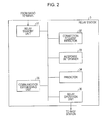
- a configuration of the relay station 3 is illustrated in Fig. 2 .
- Each element in Fig.2 may be embodied by a controller in a relay station 3 by executing a predetermined control program. The elements are described below from the standpoint of interactions thereof.
- a relay standby unit 31 stops processes that are related to the relay operation, other than a reception of the connection request from the radio terminals (including the radio terminals 4 and 5), and sets the relay station 3 into a relay standby state.
- the relay station 3 which is set in the relay standby state by the relay standby unit 31 consumes power for the reception of the connection request of the radio terminals 4 and 5 and other radio terminals.
- the reception operation is performed at the random-access channel for the transmission of the connection request of each radio terminal, based on the broadcast information, which may include resource information indicative of a radio resource for the random-access channel, which is transmitted from the base station 2.
- a connection request detector 32 detects a connection request from the radio terminal in response to the broadcast information from the base station 2 (the radio terminals 4 and 5 in the present embodiment) through the reception operation of the relay standby unit 31 at the random-access channel.
- a response determiner 33 determines whether the base station 2 has responded to each of the radio terminals having transmitted the connection request.
- a predictor 34 predicts a signal intensity or a signal quality of the connection request from each radio terminal in order to determine whether the relay operation of the relay station 3 may be reliably performed. If communications have not been established between the base station 2 and the relay station 3, a base station communication establishing unit 35 establishes the connection. If the communication is established, the base station communication establishing unit 35 maintains the communications.
- a relay operation unit 36 notifies the base station 2 of the connection request that is received from the radio terminal based on the process results of each of the above elements, and then shifts from the relay standby state to a relay operation state in order to perform relay communications between the radio terminal and the base station 2.
- a startup process of the relay station 3, including the above-described elements, is described below with reference to Figs. 3 and 4A and 4B .
- the relay station 3 leaves the relay standby state and starts up.
- the relay startup process is performed in response to the radio terminal 4 that may not directly transmit the connection request to the base station 2.
- the relay standby unit 31 determines whether a connection request from the radio terminal 4 has been received. If the answer to the determination in step S101 is non-affirmative, the relay standby unit 31 keeps the relay operation of the relay station 3 at the standby state in step S102. If the answer to the determination in step S101 is affirmative, processing proceeds to operation S103.
- the connection request detector 32 detects a connection request from the radio terminal 4.
- step S104 the relay station 3 transmits the connection request thereof to the base station 2 at the random-access channel. More specifically, in the state in which the relaying process is not started, it is not necessary that the relay station 3 be connected to the base station 2. Along with the startup of the relay station 3 for the radio terminal 4, communication is newly established between the relay station 3 and the base station 2. Subsequent to step S104, communication is established between the relay station 3 and the base station 2 in response to a response from the base station 2 (in step S105). Process steps S104 and S105 are executed by the base station communication establishing unit 35. If communication has already been established between the relay station 3 and the base station 2, then performing process steps S104 and S105 is not necessary.
- the relay operation unit 36 notifies the base station 2 of the connection request from the radio terminal 4 via the established communication (step S106).
- the relay station 3 thus shifts from the relay standby state to the relay operation state.
- the relay station 3 starts up in response to the detection of the connection request by the connection request detector 32. The startup of the relay station 3 is thus adjusted so that the overuse of power and frequency resources by the relay station 3 is controlled.
- a notification method of notifying the base station 2 of the connection request may be executed as described in Figs. 4A and 4B so that the relay operation unit 36 shifts from the relay standby state to the relay operation state.
- the connection request is transmitted at the random-access channel used by the radio terminal 4. That is, the connection request is transmitted by using a radio resource (R) (for example, random-access channel) which is defined by resource information transmitted from the base station 2 as a radio resource for transmission of connection request of the radio terminal.
- R radio resource
- the relay station 3 amplifies a connection request signal and relays the amplified connection request by using the radio resource (R).
- the connection request is transmitted to the base station 2 using a resource assigned to the relay station 2 for transmission of notification, which is different from the radio resource (for example, random-access channel) for the terminal.
- the base station 2 recognizes the connection request relayed by the relay station 3 rather than the connection request directly transmitted by the radio terminal 4.
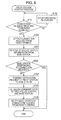
- step S201 the response determiner 33 determines whether the base station 2 has transmitted a response in response to the connection request transmitted from each radio terminal.
- the sequence of the base station 2 subsequent to the connection request performed by each radio terminal at the random-access channel is typically defined. By monitoring the sequence, the response determiner 33 determines whether the base station 2 has responded to the radio terminal having transmitted the connection request detected in step S103.
- the base station 2 may recognize the connection request from the radio terminal 5. The base station 2 thus responds to the connection request. By monitoring this process, the response determiner 33 determines that the base station 2 has responded (affirmative answer to the determination in step S201). On the other hand, the radio terminal 4 is not present within the area R2, and the base station 2 may not recognize the connection request from the radio terminal 4. The base station 2 does not respond to the connection request. By monitoring this process, the response determiner 33 determines that the base station 2 has not responded for a constant period of time since the detection of the connection request in step S103. The response determiner 33 thus determines that the base station 2 has not transmitted a response in response to the radio terminal 4 (non-affirmative answer to the determination in step S201).
- step S201 If an affirmative answer is obtained in the determination in step S201, the base station 2 directly communicates with the radio terminal 5, and it is not necessary to start up the relay station 3. In such a case, the relay station ends the process without starting the relaying operation. If a non-affirmative answer is obtained in the determination in step S201, then no direct communication is made between the radio terminal 4 and the base station 2. The relay station 3 is thus started up in step S104 and subsequent steps. The startup of the relay station 3 is properly adjusted. Therefore, the overuse of power and frequency resources by the relay station 3 is controlled.
- step S301 response status information is received from the base station 2.
- the response status information relates to the presence or absence of the connection request from the radio terminal that is recognized by the base station 2.
- the response status information explicitely indicates that the connection request from the radio terminal, the presence of which the base station 2 recognizes, fails to reach the base station 2.
- Such radio terminals include the radio terminals 4 and 5, which, although in communication with the base station 2 some moments ago, are currently disconnected from the base station 2.
- Another such device includes a radio terminal which is designed to move within either area R1 or R2 to communicate with the base station 2. Processing proceeds to step S302 subsequent to step S301.
- step S302 it is determined in step S302, in accordance with the response status information received in step S301, whether the base station 2 recognizes the radio terminal having transmitted the connection request detected in step S103 and has given a response.
- the response status information output from the base station 2 is used to determine the presence or absence of the response in response to the connection request from the radio terminal. If the answer in step S302 is non-affirmative, process step S104 and subsequent steps are executed for the relay station 3 to start the relay operation. If the answer in step S302 is affirmative, the relay station startup process ends.
- the determination process step in step S201 in the flowchart of Fig. 5 may be also executed. The overuse of power and frequency resources by the relay station 3 is thus controlled.
- step S401 as in step S201 illustrated in Fig. 5 , the response determiner 33 determines whether the base station 2 has transmitted a response in response to the connection request from the radio terminal. If the answer to step S401 is affirmative, the relay station startup process ends. If the answer to step S401 is non-affirmative, a determination operation in step S402 is performed. The order of the determination operation in step S401 and the determination operation in step S402 may be reversed in Fig. 7 .
- step S402 the predictor 34 determines whether the signal intensity or the signal quality of the connection request that is detected in step S103 satisfies the predetermined criterion of one of the signal intensity or the signal quality.
- the predictor 34 predicts the signal intensity or the signal quality of the signal expected to arrive from the radio terminal having output the connection request, i.e., the signal intensity and the signal quality of the signal expected to arrive from the radio terminal when the relay station 3 performs the relay operation, and then determines whether the predicted results satisfies the signal intensity serving as a criterion. This determination operation is performed to maintain a reliable communication state between the radio terminal and the relay station 3 so that the relay station 3 reliably performs the relay operation.
- the prediction of the predictor 34 of the signal intensity or the like of the signal from the radio terminal may be performed in accordance with a sequence or the like according to which the connection request is transmitted from the radio terminal. For example, if the signal intensity or the like of the connection request output from the radio terminal increases with time, the predictor 34 predicts how the signal intensity or the like changes at the start of the relay operation, in accordance with a rate of change of the signal intensity or the like at the radio terminal, based on the signal intensity or the like at the operation time at step S402 and a time duration until the start of the relay operation. If the answer to step S402 is affirmative, steps S104 and subsequent steps are performed for the relay station 3 to start the relay operation. If the answer to step S402 is non-affirmative, the relay station startup process ends. The startup of the relay station 3 is thus reliably executed. The relay operation performed by the relay station 3 is reliably performed.
- the relay operation is started up in response to the detection of the connection request signal from the radio terminal, the absence of the response from the base station, or the response status information from the base station.
- a signal is thus relayed between the radio terminal and the base station.
- a relay station such as a non-transparent relay station defined in IEEE draft standard P802.16j described above, may operate as an equivalent to the base station with respect to the radio terminal.
- the foregoing technical discussion of the relay station is applicable to this type of relay station.
- the relay operation in the mode equivalent to the base station may be started in response to the detection of the connection request signal from the radio terminal, the absence of the response from the base station, or the response status information from the base station.
- the radio terminal may issue a new connection request to a relay station that is started up in response to the first communication request, and operates in a manner equivalent to the base station.
- the radio terminal thus establishes communication with the relay station.
- the relay station may shift to a transparent communication state, thereby starting communication.
- the communication between the relay station and the base station may not only be radio communication separately established between the relay station and the base station, but also separately established wired communication.
- the relay station that operates in a manner equivalent to the base station with reference to the radio terminal is not limited to the base station as a relay destination.
- the relay station may be an apparatus (e.g. controller) on a communication network.
- a base station transmits the following items: i) a preamble signal for the use in synchronization, ii) radio resource information for the transmission of burst data in a down link direction (referred to as DL MAP information including transmission frequency, iii) information regarding radio resources for the use in transmission of transmission timing), and iv) radio resource information for the reception of burst data (including a random-access signal) in an up link direction (referred to as UL MAP information).
- DL MAP information radio resource information for the transmission of burst data in a down link direction
- UL MAP information radio resource information for the reception of burst data (including a random-access signal) in an up link direction
- a radio frame that is transmitted by the base station 2 is illustrated in Fig. 8B .
- the radio terminal receives the preamble signal, is synchronized with the radio frame of the base station, and then receives the UL MAP information and the DL MAP information.
- the radio terminal searches the MAP information to detect the radio resources to be used for the transmission and reception of the terminal in accordance with a connection ID assigned thereto. If the radio terminal detects that the MAP information indicates that the radio terminal should transmit or receive data by using any radio resource defined by the MAP information as a radio resource assigned to the radio terminal (connection ID), data is received or transmitted by the radio terminal according to the MAP information.
- the UL MAP information includes information specifying the radio resource for transmission of the random-access signal. The radio terminal transmits the random-access signal in the designated radio resource specified by the information.
- the relay station performs a synchronization operation by receiving the preamble information, and then receives the MAP information. The relay station then identifies a radio resource for use in transmission of the random-access signal from the radio terminal.
- the relay station includes a transceiver that is configured to transmit and receive radio signals, and a controller that is configured to control the transceiver and to exchange transmission and reception data with the transceiver. The operation of the relay station discussed below is controlled by the controller.
- the relay station receives no further MAP data (broadcast information) transmitted thereafter from the base station.
- the preamble is not received.
- the preamble for synchronization with the radio frame is transmitted intermittently from the base station, for example, every frame or every plurality of frames.
- the relay station receives in RA1 (a radio resource for transmitting Random Access signal) each frame.
- RA1 a radio resource for transmitting Random Access signal
- the received random-access signal is relayed and the MAP information transmitted from the base station starts to be received.
- the relay station itself starts transmitting and receiving the preamble signal, the MAP information, burst data (for up link and down link). It is noted that transmission and reception of the preamble signal, the MAP information, and the burst data (for up link and down link) are not performed prior to the start.
- a transmission area (RA2) within which permits the radio terminal to transmit a random-access signal, may be set up in the up link burst data.
- the relay station By receiving the MAP information from the base station, the relay station establishes a radio communication path with the base station. With reference to the radio terminal, the relay station may establish the radio communication path by transmitting the random-access signal to the base station (to a state in which data can be transmitted and received according to the MAP information with the connection ID or the like reset). The relay station transmits the MAP information in accordance with the scheduling of the base station or its own station, thereby performing radio communications with the radio terminal. The relay station thus performs the relay operation by transmitting the received data to the base station. The relay station also performs the relay operation by transmitting the received data from the base station to the radio terminal.
- the relay station may use the detection of the random-access signal from the radio terminal in the RA1 as a trigger to transmit the radio frame to the radio terminal.
- Another condition may be included as a trigger.
- the response from the base station means that communication is established between the radio terminal and the base station, and the condition that no response signal is transmitted from the base station may be used as a trigger.
- the base station may receive the random-access signal directly from the radio terminal or the random-access signal relayed by the relay station.
- the relay station receives a notification from the base station as to whether the base station has transmitted the response in response to the random-access signal. There are cases when the relay station has detected the random-access signal but the base station fails to detect the random-access signal. Such a case is detected in response to the notification from the base station.
- the relay station itself starts receiving and transmitting the preamble signal, the MAP information, and the burst data (for up link and down link).
- the relay station When a reception level or a reception quality of the random-access signal is above a predetermined (certain) criterion, the relay station performs the relay operation of the received random-access signal and starts receiving the MAP information from the base station.
- the relay station itself starts receiving and transmitting the preamble signal, the MAP information and the burst data (for up link and down link).
- power consumption is controlled.
- the power consumption and the use of radio signal resources are reduced when the relay station performs the relay operation in the radio communications between the radio terminal and the base station.
- the invention also provides a computer program or a computer program product for carrying out any of the methods described herein, and a computer readable medium having stored thereon a program for carrying out any of the methods described herein.
- a computer program embodying the invention may be stored on a computer-readable medium, or it could, for example, be in the form of a signal such as a downloadable data signal provided from an Internet website, or it could be in any other form.
Landscapes
- Engineering & Computer Science (AREA)
- Computer Networks & Wireless Communication (AREA)
- Signal Processing (AREA)
- Mobile Radio Communication Systems (AREA)
- Radio Relay Systems (AREA)
Applications Claiming Priority (1)
| Application Number | Priority Date | Filing Date | Title |
|---|---|---|---|
| JP2008088252A JP2009246508A (ja) | 2008-03-28 | 2008-03-28 | 無線通信用中継局、無線通信システムおよび中継局の制御方法 |
Publications (3)
| Publication Number | Publication Date |
|---|---|
| EP2106174A2 true EP2106174A2 (de) | 2009-09-30 |
| EP2106174A3 EP2106174A3 (de) | 2009-12-30 |
| EP2106174B1 EP2106174B1 (de) | 2014-08-13 |
Family
ID=40910987
Family Applications (1)
| Application Number | Title | Priority Date | Filing Date |
|---|---|---|---|
| EP09156316.3A Expired - Fee Related EP2106174B1 (de) | 2008-03-28 | 2009-03-26 | Relaisstation, Funkkommunikationssystem und Steuerungsverfahren der Relaisstation |
Country Status (3)
| Country | Link |
|---|---|
| US (1) | US8401463B2 (de) |
| EP (1) | EP2106174B1 (de) |
| JP (1) | JP2009246508A (de) |
Cited By (6)
| Publication number | Priority date | Publication date | Assignee | Title |
|---|---|---|---|---|
| EP2180605A1 (de) | 2008-10-27 | 2010-04-28 | Andrew Wireless Systems GmbH | Repeater und Verfahren zum Betrieb eines solchen Repeaters |
| GB2475906A (en) * | 2009-12-04 | 2011-06-08 | Sharp Kk | A relay apparatus used in connection with the lte-a standard |
| WO2012005657A1 (en) * | 2010-07-07 | 2012-01-12 | Telefonaktiebolaget L M Ericsson (Publ) | Secondary radio-nodes for mobile communications networks and related methods |
| WO2012042375A2 (en) | 2010-09-28 | 2012-04-05 | Alcatel Lucent | Base station, user equipment and method of reducing energy consumption in a base station |
| CN103765943A (zh) * | 2011-09-28 | 2014-04-30 | 富士通株式会社 | 辅助传输单元的启用 |
| US10645667B2 (en) | 2009-04-21 | 2020-05-05 | Commscope Technologies Llc | System for automatic configuration of a mobile communication system |
Families Citing this family (18)
| Publication number | Priority date | Publication date | Assignee | Title |
|---|---|---|---|---|
| US8787240B2 (en) * | 2009-04-10 | 2014-07-22 | Samsung Electronics Co., Ltd. | Peer-to-peer communication protocol for relay enhanced cellular wireless communication systems |
| GB0907213D0 (en) * | 2009-04-27 | 2009-06-10 | Sharp Kk | Relay apparatus and method |
| PL2441310T3 (pl) * | 2009-06-12 | 2020-04-30 | Nokia Technologies Oy | Sposób i urządzenie umożliwiające komunikację węzła przekaźnikowego |
| CN102598804B (zh) * | 2009-11-05 | 2016-08-17 | 夏普株式会社 | 无线通信系统、中继站装置以及无线通信方法 |
| US8755328B2 (en) | 2009-12-24 | 2014-06-17 | Nec Corporation | Relay device, relay system, relay method, radio communication system, and program |
| KR101742994B1 (ko) * | 2010-02-09 | 2017-06-15 | 엘지전자 주식회사 | 이동통신시스템에서 랜덤접속을 수행하는 방법 및 이를 위한 장치 |
| JP5399328B2 (ja) * | 2010-06-28 | 2014-01-29 | 日本電信電話株式会社 | 無線中継装置、省電力制御方法および無線中継方法 |
| JP5685011B2 (ja) * | 2010-06-28 | 2015-03-18 | 日本電信電話株式会社 | 無線中継装置および省電力制御方法 |
| KR101781356B1 (ko) * | 2011-01-28 | 2017-09-25 | 삼성전자주식회사 | 무선통신 시스템에서 고립된 단말을 지원하는 방법 및 장치 |
| JP5639716B2 (ja) * | 2011-08-26 | 2014-12-10 | 京セラ株式会社 | 無線中継装置、無線通信方法および無線中継装置を制御するプロセッサ |
| JP2013074399A (ja) * | 2011-09-27 | 2013-04-22 | Kyocera Corp | 中継装置及び通信制御方法 |
| US9107056B2 (en) | 2012-04-18 | 2015-08-11 | Qualcomm Incorporated | Small cell activation procedure |
| MX361283B (es) | 2013-02-22 | 2018-12-03 | Huawei Tech Co Ltd | Método, dispositivo y sistema de comunicación. |
| EP2887732B1 (de) * | 2013-12-19 | 2017-06-14 | Sony Corporation | Verfahren zum Betreiben eines Benutzergeräts in einem drahtlosen Funknetz |
| JP2015228618A (ja) * | 2014-06-02 | 2015-12-17 | 富士通株式会社 | 中継装置及び通信制御方法 |
| KR101771436B1 (ko) * | 2016-03-17 | 2017-08-28 | 광주과학기술원 | 멀티홉 무선 네트워크의 전이중 통신방법 |
| JP2017169121A (ja) * | 2016-03-17 | 2017-09-21 | Necプラットフォームズ株式会社 | 無線lan中継装置、ホスト装置、通信方法、および通信システム |
| JP2018198443A (ja) * | 2018-07-27 | 2018-12-13 | Necプラットフォームズ株式会社 | ホスト装置、通信方法、および通信システム |
Citations (2)
| Publication number | Priority date | Publication date | Assignee | Title |
|---|---|---|---|---|
| JP2006254155A (ja) | 2005-03-11 | 2006-09-21 | Kddi Corp | 通信装置及びマルチホップによる基地局への接続方法 |
| JP2008088252A (ja) | 2006-09-29 | 2008-04-17 | Gc Corp | マウスガード組成物 |
Family Cites Families (13)
| Publication number | Priority date | Publication date | Assignee | Title |
|---|---|---|---|---|
| JPH06105884B2 (ja) | 1986-05-06 | 1994-12-21 | 日本電気株式会社 | 無線電話システム |
| US5940771A (en) * | 1991-05-13 | 1999-08-17 | Norand Corporation | Network supporting roaming, sleeping terminals |
| SE9300162L (sv) | 1993-01-21 | 1994-07-22 | Televerket | Anordning vid mobila kommunikationssystem för att förlänga räckvidden mellan en eller flera mobila enheter och basstation |
| JP3231210B2 (ja) * | 1995-03-03 | 2001-11-19 | 株式会社日立製作所 | 無線通信システム |
| JP4472124B2 (ja) * | 2000-06-19 | 2010-06-02 | 株式会社エヌ・ティ・ティ・ドコモ | 移動無線通信方式におけるチャネル制御方法、移動無線通信システム及び移動無線通信システムにおける基地局装置 |
| JP4049013B2 (ja) * | 2003-05-08 | 2008-02-20 | Kddi株式会社 | 無線マルチホップネットワークのアクセス制御方法、中継端末及び移動端末 |
| JP4292419B2 (ja) | 2005-07-25 | 2009-07-08 | ソニー株式会社 | モニタ端末 |
| US7991420B2 (en) | 2006-02-08 | 2011-08-02 | Samsung Electronics Co., Ltd. | Dynamic RS coverage in multi-hop cellular networks |
| WO2008004099A2 (en) | 2006-06-30 | 2008-01-10 | Nokia Corporation | Sleep mode for a wireless relay in ieee 802.16 networks ( ieee project 802.16j) |
| JP4764279B2 (ja) | 2006-07-28 | 2011-08-31 | 富士通株式会社 | 中継装置 |
| JP5045029B2 (ja) * | 2006-08-21 | 2012-10-10 | 富士通株式会社 | 無線基地局 |
| JP4983208B2 (ja) * | 2006-11-07 | 2012-07-25 | 富士通株式会社 | 中継局、無線通信方法 |
| JP2009226203A (ja) | 2008-02-28 | 2009-10-08 | Fujifilm Corp | 放射線画像撮影システム、放射線画像撮影方法及びプログラム |
-
2008
- 2008-03-28 JP JP2008088252A patent/JP2009246508A/ja active Pending
-
2009
- 2009-03-24 US US12/409,786 patent/US8401463B2/en not_active Expired - Fee Related
- 2009-03-26 EP EP09156316.3A patent/EP2106174B1/de not_active Expired - Fee Related
Patent Citations (2)
| Publication number | Priority date | Publication date | Assignee | Title |
|---|---|---|---|---|
| JP2006254155A (ja) | 2005-03-11 | 2006-09-21 | Kddi Corp | 通信装置及びマルチホップによる基地局への接続方法 |
| JP2008088252A (ja) | 2006-09-29 | 2008-04-17 | Gc Corp | マウスガード組成物 |
Cited By (14)
| Publication number | Priority date | Publication date | Assignee | Title |
|---|---|---|---|---|
| US8830882B2 (en) | 2008-10-27 | 2014-09-09 | Andrew Wireless Systems Gmbh | Repeater and method for operating such a repeater |
| WO2010049054A1 (de) * | 2008-10-27 | 2010-05-06 | Andrew Wireless Systems Gmbh | Repeater und verfahren zum betrieb eines solchen repeaters |
| US10511376B2 (en) | 2008-10-27 | 2019-12-17 | Andrew Wireless Systems Gmbh | Repeater and method for operating such a repeater |
| EP2180605A1 (de) | 2008-10-27 | 2010-04-28 | Andrew Wireless Systems GmbH | Repeater und Verfahren zum Betrieb eines solchen Repeaters |
| AT13329U1 (de) * | 2008-10-27 | 2013-10-15 | Andrew Wireless Systems Gmbh | Repeater und Verfahren zum Betrieb eines solchen Repeaters |
| US10645667B2 (en) | 2009-04-21 | 2020-05-05 | Commscope Technologies Llc | System for automatic configuration of a mobile communication system |
| GB2475906A (en) * | 2009-12-04 | 2011-06-08 | Sharp Kk | A relay apparatus used in connection with the lte-a standard |
| WO2012005657A1 (en) * | 2010-07-07 | 2012-01-12 | Telefonaktiebolaget L M Ericsson (Publ) | Secondary radio-nodes for mobile communications networks and related methods |
| US8331995B2 (en) | 2010-07-07 | 2012-12-11 | Telefonaktiebolaget L M Ericsson (Publ) | Secondary radio-nodes for mobile communications networks and related methods |
| WO2012042375A3 (en) * | 2010-09-28 | 2012-07-12 | Alcatel Lucent | Base station, user equipment and method of reducing energy consumption in a base station |
| CN102421172B (zh) * | 2010-09-28 | 2015-04-08 | 上海贝尔股份有限公司 | 基站及节约基站能耗的方法 |
| CN102421172A (zh) * | 2010-09-28 | 2012-04-18 | 上海贝尔股份有限公司 | 基站、用户设备及节约基站能耗的方法 |
| WO2012042375A2 (en) | 2010-09-28 | 2012-04-05 | Alcatel Lucent | Base station, user equipment and method of reducing energy consumption in a base station |
| CN103765943A (zh) * | 2011-09-28 | 2014-04-30 | 富士通株式会社 | 辅助传输单元的启用 |
Also Published As
| Publication number | Publication date |
|---|---|
| US8401463B2 (en) | 2013-03-19 |
| EP2106174B1 (de) | 2014-08-13 |
| JP2009246508A (ja) | 2009-10-22 |
| EP2106174A3 (de) | 2009-12-30 |
| US20090247072A1 (en) | 2009-10-01 |
Similar Documents
| Publication | Publication Date | Title |
|---|---|---|
| EP2106174B1 (de) | Relaisstation, Funkkommunikationssystem und Steuerungsverfahren der Relaisstation | |
| KR102237511B1 (ko) | 무선 통신 시스템에서 단말의 통신 제어 방법 및 장치 | |
| EP2107840B1 (de) | Basisstationsgerät | |
| US8553665B2 (en) | Method for accessing hybrid network, and gateway apparatus, wireless terminal and communication system thereof | |
| US8620375B2 (en) | Method and apparatus for supporting discontinuous operation of base station in wireless communication system and control system thereof | |
| CN103765943A (zh) | 辅助传输单元的启用 | |
| KR20160120243A (ko) | 단말간 직접 통신 방법 및 장치 | |
| KR100998924B1 (ko) | 중계방식을 사용하는 무선통신시스템에서 전력을 제어하기위한 장치 및 방법 | |
| JP4534807B2 (ja) | 通信装置及びマルチホップによる基地局への接続方法 | |
| US9301270B2 (en) | Method and apparatus for synchronization for device-to-device communication | |
| KR101475814B1 (ko) | 포인트 투 포인트 통신에 기반하여 셀 커버리지 밖의단말에 대한 호를 처리하기 위한 장치 및 방법 | |
| JP5561321B2 (ja) | 無線通信装置 | |
| KR101892927B1 (ko) | 통신 시스템에서 소형 기지국의 동작을 제어하는 방법 및 그에 따른 소형 기지국 | |
| CN105052244A (zh) | 装置锚点基站 | |
| KR20120071113A (ko) | 이동 통신 시스템에서 긴급 단말의 통신을 위한 단말의 중계 방법 | |
| KR102216009B1 (ko) | 분산 무선 통신 시스템에서 동기화하는 방법 및 이를 지원하는 단말 | |
| JP2009278580A (ja) | 基地局装置 | |
| EP2394469B1 (de) | Vorrichtung und verfahren für frequenzerfassungen mithilfe zweier radios | |
| EP3398383B1 (de) | Verfahren zum betrieb eines kapillarnetzwerk-gateways | |
| WO2022240686A1 (en) | Discovery resource selection based on rsrp value of a uu link | |
| WO2023154372A1 (en) | Inter-cell service continuity | |
| WO2023287947A1 (en) | Path switch to indirect communication through relay ue device in rrc connection state other than rrc connected | |
| KR102163265B1 (ko) | 단말 간 통신을 위한 동기화 방법 및 장치 |
Legal Events
| Date | Code | Title | Description |
|---|---|---|---|
| PUAI | Public reference made under article 153(3) epc to a published international application that has entered the european phase |
Free format text: ORIGINAL CODE: 0009012 |
|
| AK | Designated contracting states |
Kind code of ref document: A2 Designated state(s): AT BE BG CH CY CZ DE DK EE ES FI FR GB GR HR HU IE IS IT LI LT LU LV MC MK MT NL NO PL PT RO SE SI SK TR |
|
| AX | Request for extension of the european patent |
Extension state: AL BA RS |
|
| PUAL | Search report despatched |
Free format text: ORIGINAL CODE: 0009013 |
|
| AK | Designated contracting states |
Kind code of ref document: A3 Designated state(s): AT BE BG CH CY CZ DE DK EE ES FI FR GB GR HR HU IE IS IT LI LT LU LV MC MK MT NL NO PL PT RO SE SI SK TR |
|
| AX | Request for extension of the european patent |
Extension state: AL BA RS |
|
| 17P | Request for examination filed |
Effective date: 20100628 |
|
| AKX | Designation fees paid |
Designated state(s): DE FR GB |
|
| 17Q | First examination report despatched |
Effective date: 20101014 |
|
| GRAP | Despatch of communication of intention to grant a patent |
Free format text: ORIGINAL CODE: EPIDOSNIGR1 |
|
| INTG | Intention to grant announced |
Effective date: 20140306 |
|
| GRAP | Despatch of communication of intention to grant a patent |
Free format text: ORIGINAL CODE: EPIDOSNIGR1 |
|
| GRAS | Grant fee paid |
Free format text: ORIGINAL CODE: EPIDOSNIGR3 |
|
| GRAA | (expected) grant |
Free format text: ORIGINAL CODE: 0009210 |
|
| INTG | Intention to grant announced |
Effective date: 20140626 |
|
| AK | Designated contracting states |
Kind code of ref document: B1 Designated state(s): DE FR GB |
|
| REG | Reference to a national code |
Ref country code: GB Ref legal event code: FG4D |
|
| REG | Reference to a national code |
Ref country code: DE Ref legal event code: R096 Ref document number: 602009025897 Country of ref document: DE Effective date: 20140918 |
|
| REG | Reference to a national code |
Ref country code: FR Ref legal event code: PLFP Year of fee payment: 7 |
|
| PGFP | Annual fee paid to national office [announced via postgrant information from national office to epo] |
Ref country code: DE Payment date: 20150102 Year of fee payment: 7 |
|
| REG | Reference to a national code |
Ref country code: DE Ref legal event code: R097 Ref document number: 602009025897 Country of ref document: DE |
|
| PGFP | Annual fee paid to national office [announced via postgrant information from national office to epo] |
Ref country code: GB Payment date: 20150108 Year of fee payment: 7 Ref country code: FR Payment date: 20150306 Year of fee payment: 7 |
|
| PLBE | No opposition filed within time limit |
Free format text: ORIGINAL CODE: 0009261 |
|
| STAA | Information on the status of an ep patent application or granted ep patent |
Free format text: STATUS: NO OPPOSITION FILED WITHIN TIME LIMIT |
|
| 26N | No opposition filed |
Effective date: 20150515 |
|
| REG | Reference to a national code |
Ref country code: DE Ref legal event code: R119 Ref document number: 602009025897 Country of ref document: DE |
|
| GBPC | Gb: european patent ceased through non-payment of renewal fee |
Effective date: 20160326 |
|
| REG | Reference to a national code |
Ref country code: FR Ref legal event code: ST Effective date: 20161130 |
|
| PG25 | Lapsed in a contracting state [announced via postgrant information from national office to epo] |
Ref country code: DE Free format text: LAPSE BECAUSE OF NON-PAYMENT OF DUE FEES Effective date: 20161001 Ref country code: FR Free format text: LAPSE BECAUSE OF NON-PAYMENT OF DUE FEES Effective date: 20160331 Ref country code: GB Free format text: LAPSE BECAUSE OF NON-PAYMENT OF DUE FEES Effective date: 20160326 |