EP2105558A2 - Serrure avec un agencement de sécurité - Google Patents
Serrure avec un agencement de sécurité Download PDFInfo
- Publication number
- EP2105558A2 EP2105558A2 EP09155729A EP09155729A EP2105558A2 EP 2105558 A2 EP2105558 A2 EP 2105558A2 EP 09155729 A EP09155729 A EP 09155729A EP 09155729 A EP09155729 A EP 09155729A EP 2105558 A2 EP2105558 A2 EP 2105558A2
- Authority
- EP
- European Patent Office
- Prior art keywords
- lock
- locking
- protective
- locking element
- lock housing
- Prior art date
- Legal status (The legal status is an assumption and is not a legal conclusion. Google has not performed a legal analysis and makes no representation as to the accuracy of the status listed.)
- Withdrawn
Links
Images


Classifications
-
- E—FIXED CONSTRUCTIONS
- E05—LOCKS; KEYS; WINDOW OR DOOR FITTINGS; SAFES
- E05B—LOCKS; ACCESSORIES THEREFOR; HANDCUFFS
- E05B17/00—Accessories in connection with locks
- E05B17/20—Means independent of the locking mechanism for preventing unauthorised opening, e.g. for securing the bolt in the fastening position
- E05B17/2003—Preventing opening by insertion of a tool, e.g. flexible, between door and jamb to withdraw the bolt
-
- E—FIXED CONSTRUCTIONS
- E05—LOCKS; KEYS; WINDOW OR DOOR FITTINGS; SAFES
- E05B—LOCKS; ACCESSORIES THEREFOR; HANDCUFFS
- E05B17/00—Accessories in connection with locks
- E05B17/20—Means independent of the locking mechanism for preventing unauthorised opening, e.g. for securing the bolt in the fastening position
- E05B17/2084—Means to prevent forced opening by attack, tampering or jimmying
-
- E—FIXED CONSTRUCTIONS
- E05—LOCKS; KEYS; WINDOW OR DOOR FITTINGS; SAFES
- E05B—LOCKS; ACCESSORIES THEREFOR; HANDCUFFS
- E05B63/00—Locks or fastenings with special structural characteristics
- E05B63/0013—Locks with rotary bolt without provision for latching
-
- E—FIXED CONSTRUCTIONS
- E05—LOCKS; KEYS; WINDOW OR DOOR FITTINGS; SAFES
- E05B—LOCKS; ACCESSORIES THEREFOR; HANDCUFFS
- E05B15/00—Other details of locks; Parts for engagement by bolts of fastening devices
- E05B15/10—Bolts of locks or night latches
Definitions
- the present invention is directed to a lock with a lock housing, in which a locking mechanism is arranged with a locking element.
- the locking element is pivotable between a first position for closing the lock and a second position for opening the lock, wherein the locking element has a movement range between the first and the second position.
- locks can be subdivided into locks having linearly movable locking elements, and locks having a locking element pivotable about a pivot axis.
- Locks with locking elements which are arranged pivotably within the lock housing, can be placed in a closed state in which the locking element protrudes from the lock housing and they can be placed in an open state in which the locking element is retracted into the lock housing.
- Locking elements which are designed for pivoting movement within the lock housing, have a hook shape in order to engage in a striking plate that forms the opposite side of the lock.
- Locks of the above-mentioned embodiment are used in doors or windows for buildings, which locks can also be used in the field of furniture such as cabinets, drawers or security containers.
- the locking element is pivotable between a first and a second position by a key in a lock cylinder, which cooperates with the locking mechanism.
- a door handle may cooperate with the lock mechanism to move the lock member between the associated positions.
- the locking element In the closed position, the locking element extends from a cuff, which forms the front of the lock housing. In the open position, the locking element is retracted into the lock housing. Consequently, due to the range of movement of the locking element in both the forend and in the front of the lock housing an opening is necessary. This opening leads to a security problem because the locking mechanism can be manipulated through said opening.
- the opening forms an entrance to reach the locking mechanism, for example by a manipulation tool. With a manipulation tool, the locking mechanism can be damaged or the mechanism can be activated such that the closed state of the locking element is transferred to the open state.
- the invention has for its object to overcome the above-mentioned disadvantages.
- the invention includes the technical teaching that a protective element is arranged within the range of motion to provide a protective shield against manipulation of the locking mechanism, wherein the protective element is designed as a displaceable element with a first end, which is connected to the locking element, and is designed with a second end which extends freely movable into the lock housing.
- the protective element according to the present invention is not designed as part of the lock housing.
- the protective element according to the invention provides a protective shield and is movably arranged between the opening in the forend and the front of the lock housing and the locking mechanism, and the locking mechanism can not be manipulated by a manipulation tool through the opening. Due to the arrangement of the protective element, which includes a connection to the locking element, the entire locking mechanism is protected against ingress over the opening. Due to the connection between the protective element and the locking element, which is independent of the pivoting position of the locking element, the locking mechanism is protected against the introduction of a manipulation tool. Due to the movable behavior of the protective element, the protective effect is further increased. Consequently, another security effect is achieved.
- the second end of the protective element is freely movable at least between an inner limiting element and an outer limiting element.
- the end of the protective element which forms the opposite side of the connection between the protective element and the locking element, has a freely movable state and extends into the lock housing. Due to the connection of the protective element to the locking element, the protective element performs a movement between different positions when the locking element is pivoted between the first and the second position. Consequently, the lock housing has at least one inner limiting element and an outer limiting element, wherein at least the inner limiting element is arranged between the movement region of the locking element and the closing mechanism or this is formed by an inner housing wall within the lock housing.
- the inner and outer boundary elements form stop devices, wherein the protective element is movably disposed between these two devices, and wherein the movement relates to the second end of the protective element, which extends freely movable in the lock housing.
- the limiting elements are formed by cylindrical elements, which may have a threaded bore for fastening parts of the closing mechanism or, for example, a cover element for covering the lock housing.
- the locking mechanism on a transmission element for interacting with a lock cylinder, wherein the transmission element is rotatably received in the lock housing.
- the transmission element forms a kind of cylinder with a driver geometry for engagement in the lock cylinder with a rotary member, which forms the opposite side of the driver geometry.
- the locking mechanism comprises a lever element which is connected to the locking element, wherein the interaction between the transmission element and the lever element has at least two gear elements.
- the first of the two transmission elements has for interaction with the transmission element on a tooth structure, wherein the first transmission element is rotatably received by a pivot pin in the lock housing.
- the connection between the two gear elements comprises a driving pin, wherein the rotational movement of the first gear element over a certain Angular range is decoupled from the rotational movement of the second gear element.
- the lever element forms a transmission element between the locking element and the second transmission element. Therefore, the lever member is received by two pivot pins, wherein the first pivot pin is mounted on the locking element and the second pivot pin is arranged on the second transmission element. Due to the kinematics between the locking element, the lever element and the rotational movement of the second transmission element, a rotational movement of the transmission element leads to a pivoting movement of the locking element.
- the lock housing comprises a face plate with an opening which is arranged in the movement region of the locking element, in which the locking element is at least partially retracted, when the locking element is pivoted to the second position for opening the lock. Consequently, the protective element is arranged across the opening to protect the locking mechanism with the transmission element, the lever element and the transmission elements against manipulation through the opening in the forend and in the front of the lock housing. Due to the arrangement of the protective element in the movement area above the opening, it is necessary to receive the protective element in a movable manner. Consequently, the connection between the locking element and the protective element comprises a pivot pin which is arranged within the locking element.
- the first end of the protective element is formed as an eyelet, which extends around the pivot pin to provide a joint between the protective element and the locking element.
- the protective element is arranged adjacent to the outer limiting element, when the locking element is pivoted to the first position for closing the lock.
- the protective element may come to rest against the inner cage wall. When the locking element is pivoted to the closed position, the protective element follows this movement.
- the outer restricting member is disposed adjacent to the forend and the protective member can move toward the opening in the forend.
- the inner restricting member and the inner cage wall constitute a movement stopper for the protective member in the second position. Consequently, the protective element is arranged adjacent to the rear side of the locking element when the locking element is arranged in the second position, wherein the second end of the protective element has a certain distance from the outer limiting element.
- the protective element may be designed as a flexible or innflexibles element, wherein by a flexibility of the protective element combined with a high-strength steel material, which is hardened and has a spring behavior, a maximum protective effect can be achieved.
- the protective element may have a straight contour or a curvature with a convex shape, which is directed towards the closing mechanism.
- the curve shape can form an alternative due to the arrangement of the protective element within the range of movement of the locking element.
- the protective element has an oblique arrangement within the lock housing when the locking element is pivoted to the first position, wherein the protection element has a vertical arrangement within the lock housing when the locking element is pivoted to the second position.
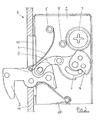
- the FIG. 1 and the FIG. 2 show a first embodiment of a lock 1 according to the present invention.
- the lock 1 comprises a lock housing 2, in which a locking mechanism is received.
- the locking mechanism comprises a locking element 3, wherein the locking element 3 is pivotable between a first position for closing the lock 1 and a second position for opening the lock 1, wherein the locking element 3 has a movement range between the first position and the second position.
- FIG. 1 the locking element 3 is shown in the closed position and can be pivoted according to the arrow shown in the open position, which by FIG. 2 is reproduced.
- a protective element 4 is arranged in the lock housing 2, which as in FIG. 1 shown is just shaped and that, as in FIG. 2 shown curved in shape.
- the lock housing 2 Due to the movement between the first and the second position of the locking element 3, the lock housing 2 has an opening 11 to allow the retracted position of the locking element 3 in the lock housing.
- the front side of the lock housing 2 is formed by a cuff 14, which also has an opening according to the opening 11.
- the protective element 4 is arranged within the range of motion to form a protective shield against manipulation of the lock housing.
- the protective element 4 is as a flexible element executed with a first end which is connected to the locking element 3 and executed with a second element, which extends freely movable into the lock housing 2.
- the security element 4 has a sheet steel material and is disposed against the locking mechanism, wherein in the closed position of the locking element 3, the protective element 4 is disposed adjacent to the outer limiting element 6 (see FIG. 2 ).
- the protective element 4 is disposed adjacent to the inner limiting element 5, wherein the limiting elements 5 and 6 are designed as a cylindrical elements with a threaded bore to a lid member on the top of the lock housing 2 assemble.
- a delimiting element 5 ' is formed by an inner cage wall, which is arranged adjacent to the delimiting element 5.
- the locking mechanism has a transmission element 7 for interaction with a lock cylinder, wherein the transmission element 7 is rotatably received within the lock housing 2 rotatably.
- the locking mechanism comprises a lever element 8, which is connected to the locking element 3.
- the connection between the transmission element 7 and the lever element 8 comprises at least two transmission elements 9 and 10.
- the transmission element 10 cooperates with the transmission element 7 and can be rotated by rotation of the transmission element 7.
- the rotation of the transmission element 10 leads to a rotation of the second transmission element 9, wherein the first transmission element 10 and the second transmission element 9 are rotatably received within the lock housing by a pivot pin 15. Consequently, the rotation of the transmission element 9 leads to a displacement of the lever element 8, which is arranged via a first and a second rotary shaft 16 and 17 between the transmission element 9 and the locking element 3.
- the latch member 3 is spring loaded by a spring member 18 to hold the latch member 3 in a preloaded condition in both the first and second positions, see FIG. 2 ,
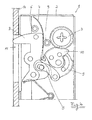
- the Figures 3 and 4 show the embodiment of the lock 1 according to the FIG. 1 wherein the locking element 3 is arranged in the second position. In this position, the locking element 3 is retracted into the lock housing 2, and the lock 1 opens the door or the assembly in which the lock 1 is mounted.
- the locking element 3 can be converted by pivoting the transmission element 7 in the clockwise direction in the second position. It follows that the first gear member 10 and the second gear member 9 are pivoted counterclockwise about the pivot pin 15. Due to the counterclockwise rotation of the transmission element 9, the lever element 8 pulls the locking element 3 in the position shown.
- the retraction of the locking element 3 in the lock housing 2 is made possible by an opening 11 in the lock housing 2 and in the forend 14, wherein the protective element 4 is moved in this position adjacent to the inner limiting element 5.
- the protective element 4 is arranged adjacent to the rear side of the locking element 3 and has a certain distance from the outer limiting element 6.
- the protective element 4 is shown as a straight-shaped element, wherein the element 4 in FIG. 4 is curved.
- FIG. 5 shows a plan view of the locking element 3, wherein the protective element 4 is connected via a pivot pin 12 on the back of the locking element 3 with the locking element 3.
- the first end of the locking element 3 has an eyelet 13 which extends around the pivot pin 12 around. Consequently, a hinge is formed between the protective element 4 and the locking element 3, to allow the Protective element 4 can move at least between the inner and the outer limiting element 5, 5 'and 6.
- the protective element 4 forms a protective shield against manipulation of the locking mechanism, regardless of the position of the locking element 3.
- the locking element 3 has a pivot pin 17, via which the lever element 8 is connected. The pivoting movement of the locking element 3 is made possible by a further pivot pin, which is mounted in the lock housing 2.
- FIG. 6 shows a further view of the locking element 3 within the lock housing 2.
- the arrangement of the protective element 4 is shown within the opening 11 on the front of the lock 2.
- the connection between the locking element 3 and the protective element 4 comprises a pivot pin 12 which is arranged in the locking element 3 in a pressed-in state.
- the first end of the protective element 4 has a bridge part 18, which has a narrower contour compared to the width of the protective element 4 over the opening 11.
- the bridge member 18 terminates in the eyelet 13 to enclose the pivot pin 12.
- the locking element 3 comprises various sheet-metal elements, which are arranged stacked on one another in order to form the thickness of the locking element 3. Consequently, the inner sheet metal elements are formed with recesses to allow enclosing the eyelet 13 of the protective element 4, wherein the outer sheet metal elements of the locking element 3 are not executed deepened and record the pivot pin 12.
Landscapes
- Engineering & Computer Science (AREA)
- Structural Engineering (AREA)
- Lock And Its Accessories (AREA)
- Details Of Indoor Wiring (AREA)
Applications Claiming Priority (1)
| Application Number | Priority Date | Filing Date | Title |
|---|---|---|---|
| DE200810016319 DE102008016319B4 (de) | 2008-03-28 | 2008-03-28 | Schloss mit einer Sicherheitseinrichtung |
Publications (2)
| Publication Number | Publication Date |
|---|---|
| EP2105558A2 true EP2105558A2 (fr) | 2009-09-30 |
| EP2105558A3 EP2105558A3 (fr) | 2011-03-02 |
Family
ID=40937383
Family Applications (1)
| Application Number | Title | Priority Date | Filing Date |
|---|---|---|---|
| EP09155729A Withdrawn EP2105558A3 (fr) | 2008-03-28 | 2009-03-20 | Serrure avec un agencement de sécurité |
Country Status (3)
| Country | Link |
|---|---|
| EP (1) | EP2105558A3 (fr) |
| CN (1) | CN101545332B (fr) |
| DE (1) | DE102008016319B4 (fr) |
Cited By (3)
| Publication number | Priority date | Publication date | Assignee | Title |
|---|---|---|---|---|
| EP2184425A1 (fr) * | 2008-11-11 | 2010-05-12 | Björkboda Las Oy AB | Boîtier de verrou |
| WO2011120845A1 (fr) * | 2010-04-01 | 2011-10-06 | Dorma Gmbh + Co. Kg | Dispositif pour protéger une serrure contre une manipulation de la serrure |
| WO2012049461A3 (fr) * | 2010-10-13 | 2012-06-21 | Iec Limited | Mécanisme |
Citations (4)
| Publication number | Priority date | Publication date | Assignee | Title |
|---|---|---|---|---|
| US4848118A (en) * | 1987-07-13 | 1989-07-18 | Adams Rite Manufacturing Co. | Lock hold-back latch with anti-pick device |
| FR2771126A1 (fr) * | 1997-11-17 | 1999-05-21 | Fontaine Sa | Serrure a commande electrique |
| FR2788077A1 (fr) * | 1998-12-31 | 2000-07-07 | Innovatech | Ensemble de serrure destine a etre pose en applique sur le montant notamment d'une porte ou portail |
| US20030127865A1 (en) * | 2002-01-07 | 2003-07-10 | U-Code, Inc. | Swing bolt lock with improved tamper resistance and method of operation |
Family Cites Families (1)
| Publication number | Priority date | Publication date | Assignee | Title |
|---|---|---|---|---|
| DE9409595U1 (de) * | 1994-06-15 | 1994-09-15 | Wurlitzer Gmbh | Türverriegelung, insbesondere für Warenautomaten |
-
2008
- 2008-03-28 DE DE200810016319 patent/DE102008016319B4/de not_active Expired - Fee Related
-
2009
- 2009-03-20 EP EP09155729A patent/EP2105558A3/fr not_active Withdrawn
- 2009-03-25 CN CN200910119380XA patent/CN101545332B/zh not_active Expired - Fee Related
Patent Citations (4)
| Publication number | Priority date | Publication date | Assignee | Title |
|---|---|---|---|---|
| US4848118A (en) * | 1987-07-13 | 1989-07-18 | Adams Rite Manufacturing Co. | Lock hold-back latch with anti-pick device |
| FR2771126A1 (fr) * | 1997-11-17 | 1999-05-21 | Fontaine Sa | Serrure a commande electrique |
| FR2788077A1 (fr) * | 1998-12-31 | 2000-07-07 | Innovatech | Ensemble de serrure destine a etre pose en applique sur le montant notamment d'une porte ou portail |
| US20030127865A1 (en) * | 2002-01-07 | 2003-07-10 | U-Code, Inc. | Swing bolt lock with improved tamper resistance and method of operation |
Cited By (7)
| Publication number | Priority date | Publication date | Assignee | Title |
|---|---|---|---|---|
| EP2184425A1 (fr) * | 2008-11-11 | 2010-05-12 | Björkboda Las Oy AB | Boîtier de verrou |
| WO2011120845A1 (fr) * | 2010-04-01 | 2011-10-06 | Dorma Gmbh + Co. Kg | Dispositif pour protéger une serrure contre une manipulation de la serrure |
| CN102834573A (zh) * | 2010-04-01 | 2012-12-19 | 多玛两合有限公司 | 用于锁的防止操作锁的保护装置 |
| CN102834573B (zh) * | 2010-04-01 | 2015-07-08 | 多玛两合有限公司 | 用于锁的防止操作锁的保护装置 |
| EP2907944A1 (fr) * | 2010-04-01 | 2015-08-19 | DORMA Deutschland GmbH | Dispositif pour protéger une serrure contre une manipulation de la serrure |
| WO2012049461A3 (fr) * | 2010-10-13 | 2012-06-21 | Iec Limited | Mécanisme |
| GB2484514B (en) * | 2010-10-13 | 2015-03-11 | Iec Ltd | A mechanism |
Also Published As
| Publication number | Publication date |
|---|---|
| DE102008016319B4 (de) | 2013-01-10 |
| CN101545332B (zh) | 2012-08-08 |
| CN101545332A (zh) | 2009-09-30 |
| DE102008016319A1 (de) | 2009-10-08 |
| EP2105558A3 (fr) | 2011-03-02 |
Similar Documents
| Publication | Publication Date | Title |
|---|---|---|
| DE3447748C2 (fr) | ||
| DE69532799T2 (de) | Verriegelung für einen behälter | |
| DE102006059568A1 (de) | Schließanlage für Türen, Fenster oder dergleichen, insbesondere Treibstangenschloss mit Panikfunktion und Mehrpunktverriegelung | |
| EP0911470A2 (fr) | Dispositif de verrouillage | |
| DE102017129427B3 (de) | Scharnierverschluss | |
| WO2009149686A1 (fr) | Dispositif de fermeture comprenant un ressort à cliquet | |
| EP3784855B1 (fr) | Serrure de véhicule automobile | |
| EP2796645B1 (fr) | Serrure à pêne dormant d'un meuble | |
| EP1049846B1 (fr) | Serrure pour porte en verre avec un element lateral fixe en verre | |
| DE102008016319B4 (de) | Schloss mit einer Sicherheitseinrichtung | |
| DE102010032742B3 (de) | Verschluss für eine Gerätetür | |
| DE102008028068B4 (de) | Elektromechanische Schließvorrichtung | |
| EP1840304A2 (fr) | Verrou à barre rotative, en particulier pour portes pivotantes de superstructures de véhicules | |
| EP3498941A1 (fr) | Élément d'actionnement pourvu d'un dispositif de verrouillage | |
| EP2093356B1 (fr) | Serrure à mécanisme de verrouillage amélioré | |
| EP2060714A2 (fr) | Crémone-serrure | |
| DE102016112554A1 (de) | Anordnung mit einem Blendrahmen zur Lagerung eines Flügelrahmens | |
| EP2738324B1 (fr) | Serrure dotée d'une unité de rotation débloquable | |
| EP0298292B1 (fr) | Serrure de porte à pêne et demi-tour coulissants | |
| EP2213818A2 (fr) | Serrure, notamment serrure à pêne dormant, de protection améliorée | |
| EP2199729A2 (fr) | Couvercle de trou d'homme pivotant, en particulier pour véhicules militaires | |
| DE102010055397B4 (de) | Verriegelungs-/Entriegelungsvorrichtung für eine Schiebetür und mit einer solchen Vorrichtung ausgestattete Tür | |
| EP0928866B1 (fr) | Serrure avec pêne à demi-tour | |
| EP1024240B1 (fr) | Dispositif de verrouillage | |
| EP2320013B1 (fr) | Armature dotée d'une transmission de renvoi |
Legal Events
| Date | Code | Title | Description |
|---|---|---|---|
| PUAI | Public reference made under article 153(3) epc to a published international application that has entered the european phase |
Free format text: ORIGINAL CODE: 0009012 |
|
| AK | Designated contracting states |
Kind code of ref document: A2 Designated state(s): AT BE BG CH CY CZ DE DK EE ES FI FR GB GR HR HU IE IS IT LI LT LU LV MC MK MT NL NO PL PT RO SE SI SK TR |
|
| AX | Request for extension of the european patent |
Extension state: AL BA RS |
|
| RAP1 | Party data changed (applicant data changed or rights of an application transferred) |
Owner name: DORMA GMBH + CO. KG |
|
| PUAL | Search report despatched |
Free format text: ORIGINAL CODE: 0009013 |
|
| AK | Designated contracting states |
Kind code of ref document: A3 Designated state(s): AT BE BG CH CY CZ DE DK EE ES FI FR GB GR HR HU IE IS IT LI LT LU LV MC MK MT NL NO PL PT RO SE SI SK TR |
|
| AX | Request for extension of the european patent |
Extension state: AL BA RS |
|
| 17P | Request for examination filed |
Effective date: 20110325 |
|
| 17Q | First examination report despatched |
Effective date: 20110418 |
|
| AKX | Designation fees paid |
Designated state(s): AT BE BG CH CY CZ DE DK EE ES FI FR GB GR HR HU IE IS IT LI LT LU LV MC MK MT NL NO PL PT RO SE SI SK TR |
|
| GRAP | Despatch of communication of intention to grant a patent |
Free format text: ORIGINAL CODE: EPIDOSNIGR1 |
|
| INTG | Intention to grant announced |
Effective date: 20140410 |
|
| RAP1 | Party data changed (applicant data changed or rights of an application transferred) |
Owner name: DORMA DEUTSCHLAND GMBH |
|
| GRAP | Despatch of communication of intention to grant a patent |
Free format text: ORIGINAL CODE: EPIDOSNIGR1 |
|
| INTG | Intention to grant announced |
Effective date: 20160628 |
|
| STAA | Information on the status of an ep patent application or granted ep patent |
Free format text: STATUS: GRANT OF PATENT IS INTENDED |
|
| STAA | Information on the status of an ep patent application or granted ep patent |
Free format text: STATUS: THE APPLICATION IS DEEMED TO BE WITHDRAWN |
|
| 18D | Application deemed to be withdrawn |
Effective date: 20161109 |
|
| RAP1 | Party data changed (applicant data changed or rights of an application transferred) |
Owner name: DORMAKABA DEUTSCHLAND GMBH |