EP2105416B1 - Glaswarenherstellungsverfahren und Maschine - Google Patents
Glaswarenherstellungsverfahren und Maschine Download PDFInfo
- Publication number
- EP2105416B1 EP2105416B1 EP09156119.1A EP09156119A EP2105416B1 EP 2105416 B1 EP2105416 B1 EP 2105416B1 EP 09156119 A EP09156119 A EP 09156119A EP 2105416 B1 EP2105416 B1 EP 2105416B1
- Authority
- EP
- European Patent Office
- Prior art keywords
- mold
- machine
- molds
- suction
- processing member
- Prior art date
- Legal status (The legal status is an assumption and is not a legal conclusion. Google has not performed a legal analysis and makes no representation as to the accuracy of the status listed.)
- Active
Links
- 238000004519 manufacturing process Methods 0.000 title claims description 10
- 239000011521 glass Substances 0.000 claims description 11
- 239000007921 spray Substances 0.000 claims description 8
- 238000000465 moulding Methods 0.000 claims description 7
- 238000000034 method Methods 0.000 claims description 6
- 230000001050 lubricating effect Effects 0.000 claims description 4
- 238000005507 spraying Methods 0.000 claims description 4
- 230000013011 mating Effects 0.000 claims description 3
- 230000001680 brushing effect Effects 0.000 claims description 2
- 239000012530 fluid Substances 0.000 claims 2
- 239000000126 substance Substances 0.000 claims 2
- 238000007790 scraping Methods 0.000 claims 1
- 239000000314 lubricant Substances 0.000 description 5
- 238000004140 cleaning Methods 0.000 description 3
- OKTJSMMVPCPJKN-UHFFFAOYSA-N Carbon Chemical compound [C] OKTJSMMVPCPJKN-UHFFFAOYSA-N 0.000 description 1
- 239000003795 chemical substances by application Substances 0.000 description 1
- 239000011248 coating agent Substances 0.000 description 1
- 238000000576 coating method Methods 0.000 description 1
- 238000010276 construction Methods 0.000 description 1
- 238000009826 distribution Methods 0.000 description 1
- 229910002804 graphite Inorganic materials 0.000 description 1
- 239000010439 graphite Substances 0.000 description 1
- 239000000463 material Substances 0.000 description 1
- 230000001681 protective effect Effects 0.000 description 1
- 230000001360 synchronised effect Effects 0.000 description 1
Images



Classifications
-
- C—CHEMISTRY; METALLURGY
- C03—GLASS; MINERAL OR SLAG WOOL
- C03B—MANUFACTURE, SHAPING, OR SUPPLEMENTARY PROCESSES
- C03B40/00—Preventing adhesion between glass and glass or between glass and the means used to shape it, hold it or support it
- C03B40/02—Preventing adhesion between glass and glass or between glass and the means used to shape it, hold it or support it by lubrication; Use of materials as release or lubricating compositions
- C03B40/027—Apparatus for applying lubricants to glass shaping moulds or tools
-
- B—PERFORMING OPERATIONS; TRANSPORTING
- B08—CLEANING
- B08B—CLEANING IN GENERAL; PREVENTION OF FOULING IN GENERAL
- B08B15/00—Preventing escape of dirt or fumes from the area where they are produced; Collecting or removing dirt or fumes from that area
- B08B15/02—Preventing escape of dirt or fumes from the area where they are produced; Collecting or removing dirt or fumes from that area using chambers or hoods covering the area
-
- B—PERFORMING OPERATIONS; TRANSPORTING
- B08—CLEANING
- B08B—CLEANING IN GENERAL; PREVENTION OF FOULING IN GENERAL
- B08B15/00—Preventing escape of dirt or fumes from the area where they are produced; Collecting or removing dirt or fumes from that area
- B08B15/04—Preventing escape of dirt or fumes from the area where they are produced; Collecting or removing dirt or fumes from that area from a small area, e.g. a tool
-
- B—PERFORMING OPERATIONS; TRANSPORTING
- B08—CLEANING
- B08B—CLEANING IN GENERAL; PREVENTION OF FOULING IN GENERAL
- B08B9/00—Cleaning hollow articles by methods or apparatus specially adapted thereto
-
- C—CHEMISTRY; METALLURGY
- C03—GLASS; MINERAL OR SLAG WOOL
- C03B—MANUFACTURE, SHAPING, OR SUPPLEMENTARY PROCESSES
- C03B40/00—Preventing adhesion between glass and glass or between glass and the means used to shape it, hold it or support it
-
- C—CHEMISTRY; METALLURGY
- C03—GLASS; MINERAL OR SLAG WOOL
- C03B—MANUFACTURE, SHAPING, OR SUPPLEMENTARY PROCESSES
- C03B40/00—Preventing adhesion between glass and glass or between glass and the means used to shape it, hold it or support it
- C03B40/02—Preventing adhesion between glass and glass or between glass and the means used to shape it, hold it or support it by lubrication; Use of materials as release or lubricating compositions
-
- C—CHEMISTRY; METALLURGY
- C03—GLASS; MINERAL OR SLAG WOOL
- C03B—MANUFACTURE, SHAPING, OR SUPPLEMENTARY PROCESSES
- C03B40/00—Preventing adhesion between glass and glass or between glass and the means used to shape it, hold it or support it
- C03B40/04—Preventing adhesion between glass and glass or between glass and the means used to shape it, hold it or support it using gas
Definitions
- the present invention relates to a glassware manufacturing method and apparatus.
- molding machines such as the type commonly known as I.S. machines, are employed comprising a number of side by side forming sections, each for producing a respective sequence of articles.
- Each forming section comprises a rough mold, normally with one or a number of adjacent mold cavities, each for receiving a glass gob and forming a respective semifinished article, which is then transferred by an inverter to a mold cavity of a finish mold to be transformed into the finished article.
- Each mold normally comprises a bottom shell; and two lateral half-molds movable with respect to each other and the relative bottom shell between a closed position, in which the lateral half-molds and the bottom shell define the mold cavities, and an open position in which enable the removal of the semifinished or finished articles from the mold.
- the molds are cleaned and lubricated regularly. This substantially consists in removing scale from the inner surfaces of the mold contacting the glass, and coating the surfaces with a release agent or lubricant, e.g. graphite-based, to prevent the glass from sticking to the inside of the mold and so producing flaws in the surface or shape of the semifinished or finished article when it is removed from the mold.
- a release agent or lubricant e.g. graphite-based
- the surfaces are normally lubricated either by hand, or by spraying the lubricant on using spray heads that can operate with the mold open or closed.
- the present invention also relates to a glassware molding machine.
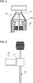
- Number 1 in Figure 1 indicates as a whole a glassware manufacturing machine comprising a supporting structure 2; and a number of adjacent known forming sections 3, not described in detail, each for forming a relative article.
- Each forming section 3 comprises a rough mold 4; a finish mold 5, in this case with two cavities; a known assembly, not shown, for transferring articles from rough mold 4 to finish mold 5; and a known assembly, not shown, for transferring the finished article from finish mold 5 to a known unloading conveyor not shown.
- Each mold 4, 5 comprises two half-molds 4a, 4b, 5a, 5b connected in known manner to a relative actuating assembly 9 ( Figures 3 , 4 ) for moving the half-molds with respect to each other between a closed position ( Figures 1 , 4 ), in which an inner surface 4c, 5c of the mold defines a seat for a mass of glass, and an open position, in which the mold permits removal of the mass of glass.
- machine 1 also comprises a mold treating assembly 10 common to all of sections 3 and for treating molds 4, 5 of sections 3.
- Assembly 10 is controlled by a respective control unit 12 synchronized with each section 3, and comprises a fixed supporting structure 11 connected to structure 2 of machine 1 and comprising a cross member 13.
- Cross member 13 extends across machine 1, crosswise to sections 3, perpendicular to the travelling direction of the masses of glass in sections 3, and, in the example shown, over molds 4, 5. In an alternative variation not shown, cross member 13 extends below a top end of mold 4, 5.
- cross member 13 is fitted integrally with a straight runner 15, along which runs both ways a powered carriage 16 forming part of assembly 10 and fitted in known manner with one end of a controlled-axis articulated arm 18 also forming part of assembly 10.
- Arm 18 is fitted on its free end with a head 19 for attaching a mold processing member 20, which may conveniently be a spray member, or a powered scraper or cleaning brush for brushing deposits off the inner surfaces of molds 4, 5, regardless of the relative position of the half-molds.
- the spray member forms the end member of a spray device 23 for spraying lubricant onto inner surface 4c, 5c of mold 4, 5, and which also comprises a pipe (not shown) for feeding lubricant to the head and connected at one end to spray member 20, and at the other end to a dispenser on or off machine 1.
- assembly 10 also comprises a suction device 24 associated with device 23 to withdraw from molds 4, 5 the exhaust produced by processing member 20. More specifically, suction device 24 comprises a suction unit 25 (shown schematically); a suction hood 26; and an exhaust conduit 27 connected to suction hood 26 at one end, and to suction unit 25 at the other.
- suction device 24 comprises a suction unit 25 (shown schematically); a suction hood 26; and an exhaust conduit 27 connected to suction hood 26 at one end, and to suction unit 25 at the other.
- suction hood 26 is designed according to the type of molds 4, 5 fitted to sections 3. More specifically, in the case of single-cavity molds, hood 26 surrounds processing member 20, and extends axially, i.e. in the same direction as processing member 20, sufficiently to house the whole of processing member 20 ( Figure 3 ), or so that the processing member projects from an axial edge 26a of hood 26, as shown in Figures 1 and 2 , by a length depending on the type of mold and how the mold is to be processed.
- a hood 26 of the above type is provided for each cavity 28, and cavities 26 are all connected to the same exhaust conduit 27.
- head 19 is fitted with a single hood 26 common to all of cavities 28, and at least partly housing a number of processing members 20 equal to the number of cavities 28.
- unit 12 given the location of the mold 4, 5 for processing, moves carriage 16 along runner 15 from a rest position, and arranges articulated arm 18 to position head 19 over the mold 4, 5 for processing, and set processing member 20, and therefore suction hood 26, to the correct operating position.
- suction unit 25 is activated, and the exhaust materials produced by processing the mold are aspirated from the mold area to prevent them settling on and fouling the machine, or being inhaled or touched by machine operators.
- head 19 is withdrawn from the processed mold 4, 5, and assembly 10 is again ready to process another mold 4, 5 or the same or a different section 3.
- the Figure 4 variation shows a machine 35 which differs in a few construction details from machine 1, and the parts of which are indicated, where possible, using the same reference numbers as for the corresponding parts of machine 1.
- Articulated arm 18 of machine 35 supports a head 36 fitted with a single hood 37, which is positioned in use facing a vertical mating plane 38 of half-molds 5a, 5b to communicate with the inside of the cavity when half-molds 5a, 5b are in the open position.
- hood 37 has a conveniently rectangular exhaust inlet 39 with a long side substantially equal to or only slightly larger than the height of half-molds 5a, 5b, and with a short side only slightly larger than the distance between the mating edges of half-molds 5a, 5b in the open position, as shown by the faint line in Figure 4 .
- Machine 35 also comprises a second articulated arm 40, which is also controlled by control unit 12, is connected at one end to carriage 16, and is fitted at the opposite end with a head 41 fitted with one or the other of said processing members 20.
- a second articulated arm 40 which is also controlled by control unit 12, is connected at one end to carriage 16, and is fitted at the opposite end with a head 41 fitted with one or the other of said processing members 20.
- head 41 is fitted with two different members 20 extending in two different directions, and which can be activated selectively, depending on how mold 4, 5 is to be processed.
- This solution obviously greatly reduces processing time, by enabling different processing of different parts of the same mold without having to retool assembly 10.
- runner 15 may be located otherwise than as described by way of example, and processing members 20 and suction hoods 26 may differ from those described.
Landscapes
- Chemical & Material Sciences (AREA)
- Engineering & Computer Science (AREA)
- Materials Engineering (AREA)
- Organic Chemistry (AREA)
- Mechanical Engineering (AREA)
- Re-Forming, After-Treatment, Cutting And Transporting Of Glass Products (AREA)
- Moulds For Moulding Plastics Or The Like (AREA)
Claims (15)
- Eine Glaswarenherstellungsmaschine (1) umfassend eine Anzahl benachbarter Formabschnitte (3), jeder zum Bilden eines entsprechenden Gegenstands; jeder Formabschnitt (3) umfassend eine Rohform (4), eine Endform (5) und eine Anordnung zum Transfer von Gegenständen aus der Rohform (4) in die Endform (5); mindestens eine Form mit zwei Halbformen, und Betätigungsmitteln (9) zum Bewegen der Halbformen relativ zueinander zwischen einer geschlossenen Position, in welcher eine Innenfläche der Form einen Sitz für eine Glasmasse definiert, und einer offenen Position, in welcher die Form das Entfernen der Glasmasse erlaubt; die Maschine (1) umfasst ebenfalls mindestens ein Verarbeitungselement (20), das allen Abschnitten gemeinsam ist und zum Behandeln der Innenflächen der Formen; Antriebsmittel (13, 16, 18, 19) zum Bewegen des gemeinsamen Verarbeitungselements zwischen den Formen der Formabschnitte (3); die Antriebsmittel umfassen einen für alle Abschnitte gemeinsamen Träger (13); ein angetriebener Schlitten (16), der in beide Richtungen entlang des Trägers (13) bewegbar ist; und ein Gelenkarm (18), der am Schlitten befestigt ist und mit einem Kopf (19) endet, an dem das Verarbeitungselement befestigt ist; Steuermittel (12), die vorgesehen sind, um das Verarbeitungselement in Bezug auf jede der Formen zwischen einer zurückgezogenen Ruheposition und einer vorderen Saugposition zu bewegen, in der die Saugmittel zumindest teilweise über der Form positioniert sind, dadurch gekennzeichnet, dass sie ferner umfasst Saugmittel (24), die mit dem gemeinsamen Verarbeitungselement (20) zugeordnet und an dem Kopf (19) befestigt sind, um die durch die Behandlung der Innenflächen abgegebenen Substanzen abzusaugen, wobei die Antriebsmittel die Saugvorrichtungen (24) zwischen den Formen der Formabschnitte bewegen; der Träger (13) sich quer über die Maschine, quer zu den Abschnitten (3) und über die Roh- (4) und Endformen (5) erstreckt.
- Eine Maschine nach Anspruch 1, dadurch gekennzeichnet, dass das Verarbeitungselement (20) eine Schaberbürste umfasst und dass die Saugvorrichtungen (24) die Schaberbürste umgeben.
- Eine Maschine nach Anspruch 1 oder 2, dadurch gekennzeichnet, dass das Verarbeitungselement (20) ein Sprühelement zum Versprühen von Schmierfluid umfasst, und dass die Saugvorrichtung das Sprühelement umgibt.
- Eine Maschine nach Anspruch 2 oder 3, dadurch gekennzeichnet, dass sie umfasst eine Anzahl an Verarbeitungselementen (20), die nebeneinander an den Antriebsmitteln montiert sind; und eine entsprechende Absaughaube (26) für jedes Verarbeitungselement.
- Eine Maschine nach Anspruch 2 oder 3, dadurch gekennzeichnet, dass sie eine Anzahl an Verarbeitungselementen (20) umfasst, die nebeneinander an den Antriebsmitteln montiert sind; und dass die Absaugmittel eine einzige Absaughaube umfassen, die allen Verarbeitungselementen (20) gemeinsam ist.
- Eine Maschine, wie sie in einem der vorstehenden Ansprüche beansprucht ist, dadurch gekennzeichnet, dass sich das Verarbeitungselement vollständig innerhalb der Saugvorrichtung (24) erstreckt.
- Eine Maschine nach einem der Ansprüche 1 bis 5, dadurch gekennzeichnet, dass das Verarbeitungselement ein längliches Element ist, das teilweise aus der Saugvorrichtung (24) herausragt.
- Eine Maschine nach Anspruch 1, dadurch gekennzeichnet, dass die Antriebsmittel umfassen einen Träger (13), der allen Abschnitten (3) gemeinsam ist, einen angetriebenen Schlitten (16), der in beide Richtungen entlang des Trägers (13) bewegbar ist, und einen Gelenkarm (18), der an dem Schlitten (16) befestigt ist und mit einem Kopf (19) endet, an dem mindestens die Saugvorrichtungen (24) befestigt sind, wobei Steuermittel (12) vorgesehen sind, um mindestens die Saugvorrichtungen in Bezug auf jede Form zwischen einer zurückgezogenen Ruheposition und einer vorderen Saugposition zu bewegen, in der die Saugvorrichtungen gegenüber einer vertikalen Verbindungslinie (38) der Halbformen positioniert sind, um mit dem Inneren des Hohlraums zu kommunizieren, wenn sich die Halbformen in der offenen Position befinden.
- Eine Maschine nach Anspruch 8, dadurch gekennzeichnet, dass sie einen weiteren Gelenkarm (40) umfasst, der an dem Schlitten (16) befestigt und von dem Gelenkarm (18) getrennt ist, wobei der weitere Gelenkarm (40) mit einem entsprechenden Kopf (41) endet, der mit mindestens einem ersten der Verarbeitungselemente ausgestattet ist.
- Eine Maschine nach Anspruch 9, dadurch gekennzeichnet, dass der Kopf des weiteren Gelenkarms mit zwei verschiedenen Verarbeitungselementen (20) ausgestattet ist, die unabhängig voneinander betrieben werden können.
- Ein Verfahren zur Herstellung von Glaswaren auf einer Glaswarengießmaschine (1), die eine Anzahl von Formabschnitten (3) umfasst, jeder zum Bilden eines entsprechenden Gegenstands, wobei das Verfahren die Schritte umfasst,• für jeden der Formabschnitte (3) eine Rohform (4), eine Endform (5) und eine Anordnung zum Übertragen von Gegenständen aus der Rohform (4) in die Endform (5) zu verwenden, wobei mindestens eine Form (4)(5) zwei Halbformen hat, die in Bezug zueinander zwischen einer geschlossenen Position, in der die Innenfläche der Form einen Sitz für eine Glasmasse definiert, und einer offenen Position, in der die Form das Entfernen der Glasmasse erlaubt, bewegbar sind,• die Innenfläche der Roh- (4) und der Endform (5) unter Verwendung eines Verarbeitungselements (20) zu behandeln,• und die Substanzen, die durch den Schritt der Behandlung der Innenfläche abgelassen werden, durch eine Saugvorrichtung (24) abzusaugen,dadurch gekennzeichnet, dass die Behandlungs- und Absaugschritte unter Verwendung eines Gelenkarms (18) durchgeführt werden, der mit einem Kopf (19) endet, an dem das Verarbeitungselement (20) und die Saugvorrichtungen (24), die allen Formabschnitten (3) gemeinsam sind, befestigt und an einem angetriebenen Schlitten (16) montiert sind, der in beide Richtungen entlang eines allen Formabschnitten gemeinsamen Trägers (13) bewegbar ist und sich über die Maschine, quer zu den Formabschnitten (3) und über die Roh- und Endformen (4) (5) erstreckt.
- Ein Verfahren nach Anspruch 11, dadurch gekennzeichnet, dass der Absaugschritt das Absaugen der Emissionen umfasst, die durch das Bürsten der Innenfläche der Form erzeugt werden.
- Ein Verfahren nach Anspruch 11, dadurch gekennzeichnet, dass der Absaugschritt das Absaugen der Emissionen umfasst, die durch das Auftragen von Schmierfluid auf die Innenfläche der Form erzeugt werden.
- Ein Verfahren nach Anspruch 12 oder 13, dadurch gekennzeichnet, dass der Absaugschritt simultan ist mit dem Schritt der Behandlung der Innenfläche.
- Ein Verfahren nach Anspruch 12 oder 13, dadurch gekennzeichnet, dass der Absaugschritt durchgeführt wird, nachdem der Schritt zur Behandlung der Innenfläche begonnen wurde.
Applications Claiming Priority (1)
| Application Number | Priority Date | Filing Date | Title |
|---|---|---|---|
| IT000234A ITTO20080234A1 (it) | 2008-03-27 | 2008-03-27 | Metodo e macchina per la realizzazione di articoli di vetro |
Publications (3)
| Publication Number | Publication Date |
|---|---|
| EP2105416A2 EP2105416A2 (de) | 2009-09-30 |
| EP2105416A3 EP2105416A3 (de) | 2013-02-27 |
| EP2105416B1 true EP2105416B1 (de) | 2019-06-19 |
Family
ID=40293298
Family Applications (1)
| Application Number | Title | Priority Date | Filing Date |
|---|---|---|---|
| EP09156119.1A Active EP2105416B1 (de) | 2008-03-27 | 2009-03-25 | Glaswarenherstellungsverfahren und Maschine |
Country Status (3)
| Country | Link |
|---|---|
| US (1) | US8240171B2 (de) |
| EP (1) | EP2105416B1 (de) |
| IT (1) | ITTO20080234A1 (de) |
Cited By (1)
| Publication number | Priority date | Publication date | Assignee | Title |
|---|---|---|---|---|
| WO2026064225A1 (en) * | 2024-09-17 | 2026-03-26 | Owens-Brockway Glass Container Inc. | Robotic blow mold lubrication |
Families Citing this family (8)
| Publication number | Priority date | Publication date | Assignee | Title |
|---|---|---|---|---|
| DE102009036920A1 (de) * | 2009-08-11 | 2011-02-17 | Krones Ag | Blasformmaschine mit Anordnung zum Reinigen der Blasform |
| DE102013019042B4 (de) * | 2013-11-15 | 2016-10-27 | Heye International Gmbh | Anordnung zur Schmierstoffversorgung einer Glasformmaschine |
| WO2016132236A1 (en) * | 2015-02-18 | 2016-08-25 | Is Engineering Ag | Method for lubricating molten glass forming molds and machine using such molds |
| EP3135640B1 (de) | 2015-08-26 | 2020-03-18 | Socabelec S.A. | Einfettung von vorformen beim herstellungsverfahren von produkten aus hohlglas |
| US11083314B2 (en) * | 2016-01-26 | 2021-08-10 | George Pietropaolo | Drinkware with lens base |
| JP6577127B1 (ja) | 2018-12-27 | 2019-09-18 | 日本山村硝子株式会社 | ガラスびん成形用金型への離型剤塗布装置 |
| CN114075030B (zh) * | 2021-11-19 | 2024-03-19 | 咸宁市汇美达工贸有限公司 | 一种玻璃器皿快速成型设备及其成型工艺 |
| CN117463525A (zh) * | 2023-11-01 | 2024-01-30 | 中国科学院西北生态环境资源研究院 | 一种按压式调压清洗喷头、容器清洗器及其清洗水槽 |
Citations (1)
| Publication number | Priority date | Publication date | Assignee | Title |
|---|---|---|---|---|
| FR2901551A1 (fr) * | 2006-05-29 | 2007-11-30 | Saint Gobain Emballage Sa | Graissage automatique des moules pour le formage de produits en verre creux |
Family Cites Families (11)
| Publication number | Priority date | Publication date | Assignee | Title |
|---|---|---|---|---|
| US3617232A (en) * | 1970-08-31 | 1971-11-02 | Anchor Hocking Corp | Self-acting connector for applying coolant air to glass molds |
| US3721542A (en) * | 1971-07-15 | 1973-03-20 | Owens Illinois Inc | Funnel arm mounted mold lubrication apparatus |
| US3814594A (en) * | 1972-11-17 | 1974-06-04 | Owens Illinois Inc | Blank mold spray |
| US3994847A (en) * | 1974-12-30 | 1976-11-30 | Ball Corporation | Aqueous dispersion of polyphenylene sulfide metal phosphate binder and solid lubricant for glass molds coating |
| US4332606A (en) * | 1980-10-27 | 1982-06-01 | Emhart Industries, Inc. | Ware identifying apparatus for glassware machines and the like |
| GB8315153D0 (en) * | 1983-06-02 | 1983-07-06 | Graphoidal Dev Ltd | Moulding |
| US4867777A (en) * | 1987-01-30 | 1989-09-19 | Ball Corporation | Apparatus and method for lubricating glassware mold |
| US4737181A (en) * | 1987-03-05 | 1988-04-12 | Vitro Tec Fideicomiso | Method and apparatus for controlling a pressing machine for the manufacture of glass articles |
| AU665905B2 (en) * | 1994-05-02 | 1996-01-18 | Yamamura Glass Co., Ltd. | Swabbing device for molds of bottle making machine |
| JP3799581B2 (ja) * | 1996-04-09 | 2006-07-19 | 旭硝子株式会社 | ガラス成形装置 |
| US7383694B2 (en) * | 2005-02-15 | 2008-06-10 | Owens-Brockway Glass Container Inc. | Lubrication assembly for glassware forming molds |
-
2008
- 2008-03-27 IT IT000234A patent/ITTO20080234A1/it unknown
-
2009
- 2009-03-25 US US12/410,549 patent/US8240171B2/en not_active Expired - Fee Related
- 2009-03-25 EP EP09156119.1A patent/EP2105416B1/de active Active
Patent Citations (1)
| Publication number | Priority date | Publication date | Assignee | Title |
|---|---|---|---|---|
| FR2901551A1 (fr) * | 2006-05-29 | 2007-11-30 | Saint Gobain Emballage Sa | Graissage automatique des moules pour le formage de produits en verre creux |
Cited By (1)
| Publication number | Priority date | Publication date | Assignee | Title |
|---|---|---|---|---|
| WO2026064225A1 (en) * | 2024-09-17 | 2026-03-26 | Owens-Brockway Glass Container Inc. | Robotic blow mold lubrication |
Also Published As
| Publication number | Publication date |
|---|---|
| US20090241601A1 (en) | 2009-10-01 |
| EP2105416A3 (de) | 2013-02-27 |
| EP2105416A2 (de) | 2009-09-30 |
| ITTO20080234A1 (it) | 2009-09-28 |
| US8240171B2 (en) | 2012-08-14 |
Similar Documents
| Publication | Publication Date | Title |
|---|---|---|
| US8240171B2 (en) | Glassware manufacturing method and machine | |
| US11975487B2 (en) | Method and device for producing 3D shaped parts using construction field tools | |
| CN105579163A (zh) | 用于浇铸模具的维护站和用于维护浇铸模具的方法 | |
| US20220219289A1 (en) | Method and apparatus for producing 3d moldings by layering technology, using a core cleaning station | |
| EP3013491B1 (de) | Vorrichtung zur entfernung von ablagerungen im inneren von rohren und verfahren zur entfernung von ablagerungen | |
| WO2017075898A1 (zh) | 正向全自动多头车床 | |
| CN87100295A (zh) | 拼合注射模及压模模腔表面喷涂设备 | |
| US20110296874A1 (en) | Automatic substitution of blank molds in the manufacture of hollow glass products | |
| KR101785572B1 (ko) | 콘택트 렌즈 성형용 듀얼 레이어 자동 몰드 인쇄시스템 | |
| EP3157878B1 (de) | Verfahren zur schmierung von giessform für geschmolzenes glas und maschine mit solchen formen | |
| JP2023510281A (ja) | 三次元構造物を製造するためのシステムおよび方法 | |
| CN102101090B (zh) | 一种立式喷粉房气动清理装置 | |
| KR100943205B1 (ko) | 컴퓨터수치제어를 통한 고속가공장치 및 그 동작방법 | |
| JP2009107091A (ja) | ガラス板の割断縁整形装置 | |
| CN110667035A (zh) | 一种螺丝刀立式注塑自动上下料系统 | |
| CA2126728A1 (en) | An apparatus and a procedure for shot-hood cleaning during the production of shells or core packets that are ready for casting | |
| CN118950608A (zh) | 清洗线 | |
| US20240052578A1 (en) | Fiber processing device with an alignment unit for displacing and positioning fibers and method for operating a fiber processing device | |
| JP3749105B2 (ja) | 鍛造プレス機のスプレーブロー装置 | |
| KR102560346B1 (ko) | 연마휠의 제조장치용 성형 준비 유닛 | |
| JP4648348B2 (ja) | ノズルの付着物除去装置 | |
| JP2005280996A (ja) | 材料を板形状に加工する機械のための板状要素の荷役装置 | |
| KR20100038591A (ko) | 비구면 렌즈 성형 장치 및 방법 | |
| JPH02212066A (ja) | ワーク表面の付着物除去装置 | |
| JPH06134743A (ja) | 型枠清掃用部品 |
Legal Events
| Date | Code | Title | Description |
|---|---|---|---|
| PUAI | Public reference made under article 153(3) epc to a published international application that has entered the european phase |
Free format text: ORIGINAL CODE: 0009012 |
|
| AK | Designated contracting states |
Kind code of ref document: A2 Designated state(s): AT BE BG CH CY CZ DE DK EE ES FI FR GB GR HR HU IE IS IT LI LT LU LV MC MK MT NL NO PL PT RO SE SI SK TR |
|
| AX | Request for extension of the european patent |
Extension state: AL BA RS |
|
| TPAC | Observations filed by third parties |
Free format text: ORIGINAL CODE: EPIDOSNTIPA |
|
| PUAL | Search report despatched |
Free format text: ORIGINAL CODE: 0009013 |
|
| AK | Designated contracting states |
Kind code of ref document: A3 Designated state(s): AT BE BG CH CY CZ DE DK EE ES FI FR GB GR HR HU IE IS IT LI LT LU LV MC MK MT NL NO PL PT RO SE SI SK TR |
|
| AX | Request for extension of the european patent |
Extension state: AL BA RS |
|
| RIC1 | Information provided on ipc code assigned before grant |
Ipc: C03B 40/00 20060101ALI20130123BHEP Ipc: B08B 15/02 20060101ALI20130123BHEP Ipc: B08B 9/36 20060101ALI20130123BHEP Ipc: C03B 40/04 20060101ALI20130123BHEP Ipc: C03B 40/027 20060101ALI20130123BHEP Ipc: C03B 40/02 20060101AFI20130123BHEP |
|
| 17P | Request for examination filed |
Effective date: 20130816 |
|
| AKX | Designation fees paid |
Designated state(s): AT BE BG CH CY CZ DE DK EE ES FI FR GB GR HR HU IE IS IT LI LT LU LV MC MK MT NL NO PL PT RO SE SI SK TR |
|
| 17Q | First examination report despatched |
Effective date: 20140416 |
|
| GRAP | Despatch of communication of intention to grant a patent |
Free format text: ORIGINAL CODE: EPIDOSNIGR1 |
|
| STAA | Information on the status of an ep patent application or granted ep patent |
Free format text: STATUS: GRANT OF PATENT IS INTENDED |
|
| RIC1 | Information provided on ipc code assigned before grant |
Ipc: C03B 40/027 20060101ALI20181206BHEP Ipc: C03B 40/04 20060101ALI20181206BHEP Ipc: B08B 9/36 20060101ALI20181206BHEP Ipc: B08B 15/04 20060101ALI20181206BHEP Ipc: C03B 40/00 20060101ALI20181206BHEP Ipc: B08B 15/02 20060101ALI20181206BHEP Ipc: C03B 40/02 20060101AFI20181206BHEP Ipc: B08B 9/00 20060101ALI20181206BHEP |
|
| INTG | Intention to grant announced |
Effective date: 20190107 |
|
| GRAS | Grant fee paid |
Free format text: ORIGINAL CODE: EPIDOSNIGR3 |
|
| GRAA | (expected) grant |
Free format text: ORIGINAL CODE: 0009210 |
|
| STAA | Information on the status of an ep patent application or granted ep patent |
Free format text: STATUS: THE PATENT HAS BEEN GRANTED |
|
| AK | Designated contracting states |
Kind code of ref document: B1 Designated state(s): AT BE BG CH CY CZ DE DK EE ES FI FR GB GR HR HU IE IS IT LI LT LU LV MC MK MT NL NO PL PT RO SE SI SK TR |
|
| REG | Reference to a national code |
Ref country code: GB Ref legal event code: FG4D |
|
| REG | Reference to a national code |
Ref country code: CH Ref legal event code: EP Ref country code: CH Ref legal event code: NV Representative=s name: ACTOSPHERE SARL, CH |
|
| REG | Reference to a national code |
Ref country code: IE Ref legal event code: FG4D |
|
| REG | Reference to a national code |
Ref country code: AT Ref legal event code: REF Ref document number: 1145287 Country of ref document: AT Kind code of ref document: T Effective date: 20190715 |
|
| REG | Reference to a national code |
Ref country code: DE Ref legal event code: R096 Ref document number: 602009058767 Country of ref document: DE |
|
| REG | Reference to a national code |
Ref country code: SE Ref legal event code: TRGR |
|
| REG | Reference to a national code |
Ref country code: NL Ref legal event code: MP Effective date: 20190619 |
|
| PG25 | Lapsed in a contracting state [announced via postgrant information from national office to epo] |
Ref country code: LT Free format text: LAPSE BECAUSE OF FAILURE TO SUBMIT A TRANSLATION OF THE DESCRIPTION OR TO PAY THE FEE WITHIN THE PRESCRIBED TIME-LIMIT Effective date: 20190619 Ref country code: HR Free format text: LAPSE BECAUSE OF FAILURE TO SUBMIT A TRANSLATION OF THE DESCRIPTION OR TO PAY THE FEE WITHIN THE PRESCRIBED TIME-LIMIT Effective date: 20190619 Ref country code: NO Free format text: LAPSE BECAUSE OF FAILURE TO SUBMIT A TRANSLATION OF THE DESCRIPTION OR TO PAY THE FEE WITHIN THE PRESCRIBED TIME-LIMIT Effective date: 20190919 Ref country code: FI Free format text: LAPSE BECAUSE OF FAILURE TO SUBMIT A TRANSLATION OF THE DESCRIPTION OR TO PAY THE FEE WITHIN THE PRESCRIBED TIME-LIMIT Effective date: 20190619 |
|
| REG | Reference to a national code |
Ref country code: LT Ref legal event code: MG4D |
|
| PG25 | Lapsed in a contracting state [announced via postgrant information from national office to epo] |
Ref country code: BG Free format text: LAPSE BECAUSE OF FAILURE TO SUBMIT A TRANSLATION OF THE DESCRIPTION OR TO PAY THE FEE WITHIN THE PRESCRIBED TIME-LIMIT Effective date: 20190919 Ref country code: LV Free format text: LAPSE BECAUSE OF FAILURE TO SUBMIT A TRANSLATION OF THE DESCRIPTION OR TO PAY THE FEE WITHIN THE PRESCRIBED TIME-LIMIT Effective date: 20190619 Ref country code: GR Free format text: LAPSE BECAUSE OF FAILURE TO SUBMIT A TRANSLATION OF THE DESCRIPTION OR TO PAY THE FEE WITHIN THE PRESCRIBED TIME-LIMIT Effective date: 20190920 |
|
| REG | Reference to a national code |
Ref country code: AT Ref legal event code: MK05 Ref document number: 1145287 Country of ref document: AT Kind code of ref document: T Effective date: 20190619 |
|
| PG25 | Lapsed in a contracting state [announced via postgrant information from national office to epo] |
Ref country code: PT Free format text: LAPSE BECAUSE OF FAILURE TO SUBMIT A TRANSLATION OF THE DESCRIPTION OR TO PAY THE FEE WITHIN THE PRESCRIBED TIME-LIMIT Effective date: 20191021 Ref country code: EE Free format text: LAPSE BECAUSE OF FAILURE TO SUBMIT A TRANSLATION OF THE DESCRIPTION OR TO PAY THE FEE WITHIN THE PRESCRIBED TIME-LIMIT Effective date: 20190619 Ref country code: NL Free format text: LAPSE BECAUSE OF FAILURE TO SUBMIT A TRANSLATION OF THE DESCRIPTION OR TO PAY THE FEE WITHIN THE PRESCRIBED TIME-LIMIT Effective date: 20190619 Ref country code: SK Free format text: LAPSE BECAUSE OF FAILURE TO SUBMIT A TRANSLATION OF THE DESCRIPTION OR TO PAY THE FEE WITHIN THE PRESCRIBED TIME-LIMIT Effective date: 20190619 Ref country code: RO Free format text: LAPSE BECAUSE OF FAILURE TO SUBMIT A TRANSLATION OF THE DESCRIPTION OR TO PAY THE FEE WITHIN THE PRESCRIBED TIME-LIMIT Effective date: 20190619 Ref country code: AT Free format text: LAPSE BECAUSE OF FAILURE TO SUBMIT A TRANSLATION OF THE DESCRIPTION OR TO PAY THE FEE WITHIN THE PRESCRIBED TIME-LIMIT Effective date: 20190619 |
|
| REG | Reference to a national code |
Ref country code: DE Ref legal event code: R082 Ref document number: 602009058767 Country of ref document: DE Representative=s name: TERPATENT PATENTANWAELTE TER SMITTEN EBERLEIN-, DE |
|
| PG25 | Lapsed in a contracting state [announced via postgrant information from national office to epo] |
Ref country code: IS Free format text: LAPSE BECAUSE OF FAILURE TO SUBMIT A TRANSLATION OF THE DESCRIPTION OR TO PAY THE FEE WITHIN THE PRESCRIBED TIME-LIMIT Effective date: 20191019 Ref country code: ES Free format text: LAPSE BECAUSE OF FAILURE TO SUBMIT A TRANSLATION OF THE DESCRIPTION OR TO PAY THE FEE WITHIN THE PRESCRIBED TIME-LIMIT Effective date: 20190619 Ref country code: IT Free format text: LAPSE BECAUSE OF FAILURE TO SUBMIT A TRANSLATION OF THE DESCRIPTION OR TO PAY THE FEE WITHIN THE PRESCRIBED TIME-LIMIT Effective date: 20190619 |
|
| PG25 | Lapsed in a contracting state [announced via postgrant information from national office to epo] |
Ref country code: TR Free format text: LAPSE BECAUSE OF FAILURE TO SUBMIT A TRANSLATION OF THE DESCRIPTION OR TO PAY THE FEE WITHIN THE PRESCRIBED TIME-LIMIT Effective date: 20190619 |
|
| PG25 | Lapsed in a contracting state [announced via postgrant information from national office to epo] |
Ref country code: DK Free format text: LAPSE BECAUSE OF FAILURE TO SUBMIT A TRANSLATION OF THE DESCRIPTION OR TO PAY THE FEE WITHIN THE PRESCRIBED TIME-LIMIT Effective date: 20190619 Ref country code: PL Free format text: LAPSE BECAUSE OF FAILURE TO SUBMIT A TRANSLATION OF THE DESCRIPTION OR TO PAY THE FEE WITHIN THE PRESCRIBED TIME-LIMIT Effective date: 20190619 |
|
| PGFP | Annual fee paid to national office [announced via postgrant information from national office to epo] |
Ref country code: SE Payment date: 20200227 Year of fee payment: 12 Ref country code: DE Payment date: 20200218 Year of fee payment: 12 |
|
| PG25 | Lapsed in a contracting state [announced via postgrant information from national office to epo] |
Ref country code: IS Free format text: LAPSE BECAUSE OF FAILURE TO SUBMIT A TRANSLATION OF THE DESCRIPTION OR TO PAY THE FEE WITHIN THE PRESCRIBED TIME-LIMIT Effective date: 20200224 |
|
| PGFP | Annual fee paid to national office [announced via postgrant information from national office to epo] |
Ref country code: CZ Payment date: 20200224 Year of fee payment: 12 Ref country code: CH Payment date: 20200221 Year of fee payment: 12 |
|
| REG | Reference to a national code |
Ref country code: DE Ref legal event code: R097 Ref document number: 602009058767 Country of ref document: DE |
|
| PLBE | No opposition filed within time limit |
Free format text: ORIGINAL CODE: 0009261 |
|
| STAA | Information on the status of an ep patent application or granted ep patent |
Free format text: STATUS: NO OPPOSITION FILED WITHIN TIME LIMIT |
|
| PG2D | Information on lapse in contracting state deleted |
Ref country code: IS |
|
| 26N | No opposition filed |
Effective date: 20200603 |
|
| PG25 | Lapsed in a contracting state [announced via postgrant information from national office to epo] |
Ref country code: SI Free format text: LAPSE BECAUSE OF FAILURE TO SUBMIT A TRANSLATION OF THE DESCRIPTION OR TO PAY THE FEE WITHIN THE PRESCRIBED TIME-LIMIT Effective date: 20190619 |
|
| PG25 | Lapsed in a contracting state [announced via postgrant information from national office to epo] |
Ref country code: MC Free format text: LAPSE BECAUSE OF FAILURE TO SUBMIT A TRANSLATION OF THE DESCRIPTION OR TO PAY THE FEE WITHIN THE PRESCRIBED TIME-LIMIT Effective date: 20190619 |
|
| REG | Reference to a national code |
Ref country code: BE Ref legal event code: MM Effective date: 20200331 |
|
| PG25 | Lapsed in a contracting state [announced via postgrant information from national office to epo] |
Ref country code: LU Free format text: LAPSE BECAUSE OF NON-PAYMENT OF DUE FEES Effective date: 20200325 |
|
| PG25 | Lapsed in a contracting state [announced via postgrant information from national office to epo] |
Ref country code: IE Free format text: LAPSE BECAUSE OF NON-PAYMENT OF DUE FEES Effective date: 20200325 Ref country code: FR Free format text: LAPSE BECAUSE OF NON-PAYMENT OF DUE FEES Effective date: 20200331 |
|
| PG25 | Lapsed in a contracting state [announced via postgrant information from national office to epo] |
Ref country code: BE Free format text: LAPSE BECAUSE OF NON-PAYMENT OF DUE FEES Effective date: 20200331 |
|
| GBPC | Gb: european patent ceased through non-payment of renewal fee |
Effective date: 20200325 |
|
| PG25 | Lapsed in a contracting state [announced via postgrant information from national office to epo] |
Ref country code: GB Free format text: LAPSE BECAUSE OF NON-PAYMENT OF DUE FEES Effective date: 20200325 |
|
| REG | Reference to a national code |
Ref country code: DE Ref legal event code: R119 Ref document number: 602009058767 Country of ref document: DE |
|
| PG25 | Lapsed in a contracting state [announced via postgrant information from national office to epo] |
Ref country code: CZ Free format text: LAPSE BECAUSE OF NON-PAYMENT OF DUE FEES Effective date: 20210325 |
|
| REG | Reference to a national code |
Ref country code: CH Ref legal event code: PL |
|
| PG25 | Lapsed in a contracting state [announced via postgrant information from national office to epo] |
Ref country code: LI Free format text: LAPSE BECAUSE OF NON-PAYMENT OF DUE FEES Effective date: 20210331 Ref country code: CH Free format text: LAPSE BECAUSE OF NON-PAYMENT OF DUE FEES Effective date: 20210331 Ref country code: SE Free format text: LAPSE BECAUSE OF NON-PAYMENT OF DUE FEES Effective date: 20210326 Ref country code: DE Free format text: LAPSE BECAUSE OF NON-PAYMENT OF DUE FEES Effective date: 20211001 |
|
| PG25 | Lapsed in a contracting state [announced via postgrant information from national office to epo] |
Ref country code: MT Free format text: LAPSE BECAUSE OF FAILURE TO SUBMIT A TRANSLATION OF THE DESCRIPTION OR TO PAY THE FEE WITHIN THE PRESCRIBED TIME-LIMIT Effective date: 20190619 Ref country code: CY Free format text: LAPSE BECAUSE OF FAILURE TO SUBMIT A TRANSLATION OF THE DESCRIPTION OR TO PAY THE FEE WITHIN THE PRESCRIBED TIME-LIMIT Effective date: 20190619 |
|
| PG25 | Lapsed in a contracting state [announced via postgrant information from national office to epo] |
Ref country code: MK Free format text: LAPSE BECAUSE OF FAILURE TO SUBMIT A TRANSLATION OF THE DESCRIPTION OR TO PAY THE FEE WITHIN THE PRESCRIBED TIME-LIMIT Effective date: 20190619 |