EP2101948B1 - Dispositif et procédé de positionnement d'un outil ou d'une pièce sur une machine-outil - Google Patents
Dispositif et procédé de positionnement d'un outil ou d'une pièce sur une machine-outil Download PDFInfo
- Publication number
- EP2101948B1 EP2101948B1 EP07819627.6A EP07819627A EP2101948B1 EP 2101948 B1 EP2101948 B1 EP 2101948B1 EP 07819627 A EP07819627 A EP 07819627A EP 2101948 B1 EP2101948 B1 EP 2101948B1
- Authority
- EP
- European Patent Office
- Prior art keywords
- tool
- workpiece
- centring
- centring elements
- holding means
- Prior art date
- Legal status (The legal status is an assumption and is not a legal conclusion. Google has not performed a legal analysis and makes no representation as to the accuracy of the status listed.)
- Active
Links
Images
Classifications
-
- B—PERFORMING OPERATIONS; TRANSPORTING
- B23—MACHINE TOOLS; METAL-WORKING NOT OTHERWISE PROVIDED FOR
- B23H—WORKING OF METAL BY THE ACTION OF A HIGH CONCENTRATION OF ELECTRIC CURRENT ON A WORKPIECE USING AN ELECTRODE WHICH TAKES THE PLACE OF A TOOL; SUCH WORKING COMBINED WITH OTHER FORMS OF WORKING OF METAL
- B23H7/00—Processes or apparatus applicable to both electrical discharge machining and electrochemical machining
- B23H7/26—Apparatus for moving or positioning electrode relatively to workpiece; Mounting of electrode
-
- B—PERFORMING OPERATIONS; TRANSPORTING
- B23—MACHINE TOOLS; METAL-WORKING NOT OTHERWISE PROVIDED FOR
- B23Q—DETAILS, COMPONENTS, OR ACCESSORIES FOR MACHINE TOOLS, e.g. ARRANGEMENTS FOR COPYING OR CONTROLLING; MACHINE TOOLS IN GENERAL CHARACTERISED BY THE CONSTRUCTION OF PARTICULAR DETAILS OR COMPONENTS; COMBINATIONS OR ASSOCIATIONS OF METAL-WORKING MACHINES, NOT DIRECTED TO A PARTICULAR RESULT
- B23Q1/00—Members which are comprised in the general build-up of a form of machine, particularly relatively large fixed members
- B23Q1/0063—Connecting non-slidable parts of machine tools to each other
- B23Q1/0072—Connecting non-slidable parts of machine tools to each other using a clamping opening for receiving an insertion bolt or nipple
-
- B—PERFORMING OPERATIONS; TRANSPORTING
- B23—MACHINE TOOLS; METAL-WORKING NOT OTHERWISE PROVIDED FOR
- B23Q—DETAILS, COMPONENTS, OR ACCESSORIES FOR MACHINE TOOLS, e.g. ARRANGEMENTS FOR COPYING OR CONTROLLING; MACHINE TOOLS IN GENERAL CHARACTERISED BY THE CONSTRUCTION OF PARTICULAR DETAILS OR COMPONENTS; COMBINATIONS OR ASSOCIATIONS OF METAL-WORKING MACHINES, NOT DIRECTED TO A PARTICULAR RESULT
- B23Q3/00—Devices holding, supporting, or positioning work or tools, of a kind normally removable from the machine
- B23Q3/18—Devices holding, supporting, or positioning work or tools, of a kind normally removable from the machine for positioning only
Definitions
- the invention relates to a device for positioning a tool or workpiece, such.
- Such a device is z. B. from the EP 0818 270 A1 known.
- the DE 41 16 103 A1 is a to be attached to a spark erosion machine pallet tensioner and the tool, for.
- As an electrode, carrying pallet provided.
- the pallet has a square layout.
- Pallet tensioner and pallet are provided with congruent, prismatic grooves in which cylindrical centering rollers are inserted.
- the prismatic grooves of the pallet or the corresponding grooves on the pallet tensioner are located in the corner areas of the square pallet or the square coupling part of the pallet tensioner and run diagonally.
- This type of coupling device is characterized by high precision and thus high reproducibility for tool centering.
- the rigidity against radial loads without increasing the space requirements and the design effort is increased.
- the DE 199 07 100 A1 described device for positioning a tool or workpiece on a machine tool has a holder which is connected to the machine tool.
- the holder includes receiving means for the workpiece associated centering pins.
- the receiving means consist of two intersecting at a predetermined angle centering, in which engage the centering pins.
- EP 0 849 034 A1 such as EP 0 111 092 A1 described.
- the known positioning devices it is necessary that the tool or workpiece and the holder are aligned exactly with each other. For this purpose, the individual recordings or recording devices must be forcibly positioned on the workpiece. This is complicated and costly. In addition, the previously known devices are characterized by a relatively large footprint.
- the present invention has for its object to provide a device for positioning a tool or workpiece on a machine tool and a method thereof, which is characterized by a simple application and yet allows a high-precision adjustment of the workpiece or tool on the machine tool. In addition, the necessary space is to be reduced.
- the invention is essentially based on the fact that the centering elements on the tool or workpiece as separate parts used and fixed there by special holding means and thus permanently.
- the method for positioning a tool or workpiece, such. B. an electrode on a machine tool, such. B. a Senkerodiermaschine comprises the method steps of claim 16.
- the centering on the tool or workpiece are still somewhat mobile and only then is ensured by suitable holding means that the centering elements are permanently and properly fixed.
- the holding means may be adhesives.
- the centering elements are permanently fixed in the process by other means, for example by bracing, pressing, clamping or the like. It only has to be ensured that, at the beginning of insertion, the centering elements on the tool or workpiece are initially somewhat mobile and only then permanently fixed.
- the permanent fixing of the centering takes place by placing the tool or workpiece with inserted, still moving centering on a holder that may be formed as a reference holder or is already attached to the tool.
- the centering elements can align thanks to their still possible mobility in the determined by the holder or reference holder, exact position, ie z. B. twist and / or move.
- the thus aligned centering elements are then permanently fixed after their exact alignment, z. B. in that they are glued in the aligned position.
- the holder of the machine tool or a corresponding reference holder has receptacles for the centering elements.
- These recordings of the holder can be designed as protruding from a main surface of the holder burrs, strips or rollers or balls, which z. B. at right angles to each other.
- Suitable centering elements have groove-shaped recesses which engage in these ridges, strips, balls or rollers. These recesses in the centering elements, z. B. prismatic, U-shaped or V-shaped.
- the centering elements are arranged at the same distance from the center axis of the tool or workpiece.
- bores are present in the workpiece or tool for the centering, in which the centering elements are inserted.
- each centering a plug-in part for insertion into the bore and a subsequent to the male part, wider in diameter trained gripping part.
- the gripping part of a centering element as already mentioned, z. B. provided with a prism-shaped recess which engage in the protruding ridges or strips of the holder.
- distance bolts are arranged on the tool or workpiece, by which the axial distance from the tool or workpiece is fixed to the holder.
- the spacer bolts are detachably mounted on the tool or workpiece, for. B. by screwing.
- the spacers In order to ensure the most level possible support surface, the spacers have flat top sides on which the holder can sit.
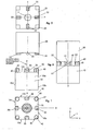
- FIG. 1 is a block-like tool or workpiece 10 shown in side view and top view.
- the tool or workpiece 10 may be, for example, an electrode for an erosion machine.
- the tool or workpiece 10 has four side surfaces 10a, 10b, 10c and 10d and a top 10e, which serves as a reference surface or end face.
- the top 10e is parallel to an area spanned by the coordinates Y and X of a rectangular coordinate system. Perpendicular to these coordinates Y and X is the coordinate Z.
- both centering elements 30 and spacing bolts 40 are seated on the upper side 10e of this tool 10.
- the spacers 40 are located at the four corners of the tool 10.
- the centering elements 30 are disposed between these spacers 40.
- the spacer bolts 40 have a planar top 42, so that a holder 20, which is connected to a machine tool, for example a Senkerodiermaschine, here can rest flat.
- a clamping bolt 60 In the middle of the tool 10 sits a clamping bolt 60, which is screwed for example for this purpose in a corresponding hole.
- Such a holder 20 is in FIG. 2 shown in side view and top view.
- This holder 20 is also designed block-like. However, the holder 20 could also be circular or have any other outer contour. It is only important that the holder 20 has a main surface 23 on which the flat surfaces 42 of the spacer bolts 40 of the tool 10 sit as level as possible. In the embodiment of FIG. 2 are located at the four corners of the holder 20 surface elements 23, which sit exactly to each other in a plane plane corresponding to the XY coordinates.
- the holder 20 has a central bore 21 for receiving the FIG. 1
- the holder 20 has four strips or ridges 22, which serve as receptacles for the centering elements 30. These strips 22 are arranged crosswise to each other. The ridges or strips 22 engage in the U-shaped or prism-shaped recesses 32 of the centering elements 30.
- FIG. 3 the tool or workpiece 10 is shown mounted on the holder 20. It can be clearly seen that the flat top sides 42 of the spacer bolts 40 on the Placed surfaces 23 of the holder 20, wherein the strips or ridges 22 of the holder 20 engage in the centering elements 30.
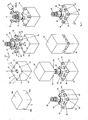
- FIG. 4 is shown in the upper left, the tool 10, for example an electrode, which is not yet suitable to be clamped on a machine tool, for example, a Senkerodiermaschine.
- the bottom right the same tool 10 is shown with inserted centering elements 30, spacers 40 and clamping bolt 60, as it can be clamped to a machine tool.
- the manufacturing path of the tool 10 is in FIG. 4 from top left to bottom right.
- the already known reference numerals will continue to be used for the same parts.
- the same coordinate system XYZ continues to be used.
- a relatively large, central bore 11 is introduced into the tool 10 for receiving a known clamping bolt 60.
- the bore 11 is preferably a screw hole.
- holes 13, preferably screw holes, are incorporated for receiving the abovementioned spacer bolts 40.
- the centering elements 30 and spacer bolts 40 are inserted into the bores 12 and 13 provided for this purpose.
- the spacers 40 are in the holes 13 z. B. screwed.
- the spacers 40 on a threaded pin 41, which cooperates with the thread in the bore 13.
- the standoffs 40 are suitably screwed into the holes 13 with a wrench.
- the spacers 40 are tightened with a predetermined torque.
- the planar surfaces 42 of the spacer bolts 40 are all ideally mounted on a common plane, which is clamped parallel to the coordinates XY when correctly mounted. In the central bore 11 of the clamping bolt 60 is inserted or screwed.
- the centering elements 30 each have a lower plug-in part 31 which can be inserted into the bores 12.
- this plug-in part 31 of each centering element 30 is added to a widened portion, wherein ideally the transition from the male part 31 to this widened gate, which has a U-shaped or prism-shaped recess 32, is rectangular, so that the centering element 30 well on the front side 10e of the tool 10 can sit.
- the holes 12 in the tool 10 are made slightly larger than the diameter of the plug-in parts 31 of the centering elements 30, so that the centering elements 30 after insertion into the corresponding holes 12 are still rotatable in the circumferential direction and slightly displaceable in the XY direction.
- 12 is used when inserting the male parts 31 of the centering elements 30 in the holes.
- some adhesive is dropped before inserting the plug-in parts 31 into the holes 12.
- a threadlocking adhesive can be used as an adhesive.
- FIG. 4 bottom left both the clamping screw 60 and the spacer bolts 40 and the centering elements 30 are shown inserted into the tool 10. It should be noted that the adhesive is not yet cured and therefore the centering elements 30 are still movable, that is rotatable and displaceable.
- a precisely crafted holder 20 for example a reference holder, provided whose ridges or strips 22 are placed accurately.
- This holder 20 is placed on the coarse pre-aligned centering elements 30.
- the strips 22 begin to engage in the recesses 32 of the centering elements 30. Due to the U-shaped or prism-shaped configuration of the recesses 32, the centering elements 30 align themselves slowly with increasing settling of the holder 20 in the direction of the workpiece 10 exactly. As soon as the holder 20 is seated on the flat surfaces 42 of the spacer bolts 40, the lowest position of the holder 20 is reached. It is then waited until the adhesive hardens. This can take a few minutes, for example. After the adhesive has cured, the reference holder 20 can be removed because the centering elements 30 are aligned on the one hand exactly and on the other hand can no longer be twisted or moved due to the curing of the adhesive. In order for a tool 10 is provided, which has in this way exactly aligned centering elements 30, so that the tool 10 can be clamped on the machine tool.
Claims (18)
- Dispositif de positionnement d'un outil ou d'une pièce à usiner (10) sur une machine outil comportant un élément de maintien (20) qui est relié à la machine outil et l'outil ou la pièce à usiner, l'outil ou la pièce à usiner (10) comportant des perçages (12) de réception d'éléments de centrage, un boulon de serrage central (60) et des éléments de centrage (30) équipés d'une partie d'enfichage (31), qui sont reliés solidairement entant qu'élément séparés avec l'outil ou la pièce à usiner (10), l'élément de maintien (20) comportant un perçage central (11) pour la réception du boulon de serrage (60),
caractérisé en ce que
les perçages (12) pour les éléments de centrage sont essentiellement plus grands que la partie d'enfichage (31) de l'élément de centrage (30) pour permettre une orientation des éléments de centrage (30) dans les perçages, les éléments de centrage (30) sont fixés et reliés rigidement à l'outil ou à la pièce à usiner (10) par l'intermédiaire de moyens adhésifs et des boulons d'écartement (40) sont montés sur l'outil ou sur la pièce à usiner (10). - Dispositif conforme à la revendication 1,
caractérisé en ce que
l'outil ou à la pièce à usiner (10) est une électrode susceptible d'être positionnée sur une machine d'usinage par étincelage. - Dispositif conforme à la revendication 1 ou 2,
caractérisé en ce que
les logements de réception (22) sont réalisés sous la forme d'éléments en saillie, en particulier d'arêtes saillantes, de barrettes ou de rouleaux. - Dispositif conforme à l'une des revendications 1 à 3,
caractérisé en ce qu'
il est prévu quatre éléments de centrage (30) qui sont décalés d'un angle de 90° les uns par rapport aux autres autours de l'axe médian (Z) de l'outil ou de la pièce à usiner (10). - Dispositif conforme à la revendication 4,
caractérisé en ce que
les éléments de centrage (30) sont respectivement situés à la même distance de l'axe médian (Z) de l'outil ou de la pièce à usiner (10). - Dispositif conforme à l'une des revendications 1 à 5,
caractérisé en ce que
dans l'outil ou la pièce à usiner (10) sont prévus des perçages dans lesquels peuvent être enfichés les éléments de centrage (30), chacun des éléments de centrage (30) comportant une partie d'enfichage (31) pour permettre son enfichage dans le perçage (12) ainsi qu'une partie de préhension (35) se raccordant à la partie d'enfichage (31) et ayant un diamètre supérieur, la partie de préhension (35) d'un élément de centrage (30) comportant un évidement prismatique (32) qui vient en prise dans le logement en saillie (22) de l'élément de maintien (20). - Dispositif conforme à la revendication 6,
caractérisé en ce que
la partie de préhension (35) d'un élément de centrage (30) comporte deux parois planes (33) s'étendant parallèlement l'une à l'autre sur la face externe de l'élément de centrage (30). - Dispositif conforme à la revendication 7,
caractérisé en ce que
l'outil ou la pièce à usiner (10) comporte des parois latérales (10a, 10b) et une paroi plane (33) d'une broche de centrage (30) est située lors d'un positionnement correct de la broche de centrage (30) sur le même plan qu'une paroi latérale (10a, 10b) de l'outil ou de la pièce à usiner (10). - Dispositif conforme à l'une des revendications 1 à 8,
caractérisé en ce que
sur l'outil ou la pièce à usiner (10) sont montés des boulons d'écartement (40) par l'intermédiaire desquels la distance axiale de l'outil ou de la pièce à usiner (10) à un élément de maintien de référence (20) est fixée. - Dispositif conforme à la revendication 9,
caractérisé en ce que
les boulons d'écartement (40) sont montés amovibles sur l'outil ou sur la pièce à usiner (10). - Dispositif conforme à la revendication 10,
caractérisé en ce que
les boulons d'écartement (40) sont vissés dans l'outil ou la pièce à usiner (10). - Dispositif conforme à l'une des revendications 10 et 11,
caractérisé en ce que
les boulons d'écartement (40) comportent des faces supérieures planes (42). - Dispositif conforme à l'une des revendications 1 à 12,
caractérisé en ce que
l'outil ou la pièce à usiner (10) comporte un perçage central (11) dans laquelle est logé un boulon de serrage (60). - Dispositif conforme à l'une des revendications 1 à 13,
caractérisé en ce qu'
il est prévu un élément de maintien de référence (20) comprenant quatre logements de réception (22) pour les éléments de centrage (30) de l'outil ou de la pièce à usiner (10). - Dispositif conforme à l'une des revendications 1 à 14,
caractérisé en ce que
les logements de réception (22) sont des becs de centrage. - Dispositif de positionnement d'un outil ou d'une pièce à usiner (10) sur une machine outil comportant les étapes suivantes consistant à :- préparer un élément de maintien de référence (20) comportant des logements de réception (22) pour des éléments de centrage (30) qui sont fixés sur un outil ou sur une pièce à usiner (10),- préparer un outil ou une pièce à usiner (10) comportant un perçage central (11) pour la réception d'un boulon de serrage (60) et des perçages (12) pour la réception d'élément de centrage (30),- introduction du boulon de serrage (60) dans le perçage central (11),- introduction des éléments de centrage (30) dans les perçages (12) en utilisant des moyens de maintien, les éléments de centrage (30) étant encore mobiles,- positionner l'outil ou la pièce à usiner (10) y compris les éléments de centrage (30) mis en place sur l'élément de maintien de référence (20), les éléments de centrage (30) venant en prise dans les logements de réception (22) de l'élément de maintien de référence (20) et s'y orientant pendant la mise en place,- fixation permanente des éléments de centrage (30),- extraction de l'outil ou de la pièce à usiner (10) de l'élément de maintien de référence (20) puis serrage dans l'élément de maintien de la machine outil.
- Procédé conforme à la revendication 16,
caractérisé en ce que
les éléments de centrage (30) sont déjà préalablement orientés manuellement lors de leur enfichage dans les perçages (12) de l'outil ou de la pièce à usiner (10). - Procédé conforme à la revendication 16 ou 17,
caractérisé en ce que
les éléments de maintien sont des moyens adhésifs, la fixation permanente des éléments de centrage (30) étant effectuée par durcissement des moyens adhésifs.
Applications Claiming Priority (2)
| Application Number | Priority Date | Filing Date | Title |
|---|---|---|---|
| DE200610054660 DE102006054660B4 (de) | 2006-11-17 | 2006-11-17 | Vorrichtung und Verfahren zum Positionieren eines Werkzeugs oder Werkstücks auf eine Werkzeugmaschine |
| PCT/EP2007/009608 WO2008058655A1 (fr) | 2006-11-17 | 2007-11-06 | Dispositif et procédé de positionnement d'un outil ou d'une pièce sur une machine-outil |
Publications (2)
| Publication Number | Publication Date |
|---|---|
| EP2101948A1 EP2101948A1 (fr) | 2009-09-23 |
| EP2101948B1 true EP2101948B1 (fr) | 2014-05-14 |
Family
ID=39102989
Family Applications (1)
| Application Number | Title | Priority Date | Filing Date |
|---|---|---|---|
| EP07819627.6A Active EP2101948B1 (fr) | 2006-11-17 | 2007-11-06 | Dispositif et procédé de positionnement d'un outil ou d'une pièce sur une machine-outil |
Country Status (3)
| Country | Link |
|---|---|
| EP (1) | EP2101948B1 (fr) |
| DE (1) | DE102006054660B4 (fr) |
| WO (1) | WO2008058655A1 (fr) |
Families Citing this family (4)
| Publication number | Priority date | Publication date | Assignee | Title |
|---|---|---|---|---|
| DE102010011947A1 (de) * | 2010-02-17 | 2011-08-18 | Illinois Tool Works Inc., Ill. | Anschlusselement zum Ausbilden einer Schnittstelle zwischen zwei lösbar miteinander verbindbaren Teilen einer Werkzeugmaschine sowie Verfahren zum Herstellen eines solchen Anschlusselements |
| CH703777A2 (de) * | 2010-09-14 | 2012-03-15 | Parotec Ag | Vorrichtung zur positionsdefinierten Aufspannung eines Gegenstandes. |
| DE102012111548B4 (de) | 2012-11-28 | 2014-07-10 | Hirschmann Gmbh | Vorrichtung zum Positionieren eines rohrförmigen Werkstückes |
| CN115780858A (zh) * | 2022-11-23 | 2023-03-14 | 佛山市禅城燃气有限公司 | 一种管道开孔装置 |
Family Cites Families (11)
| Publication number | Priority date | Publication date | Assignee | Title |
|---|---|---|---|---|
| JPS5928738Y2 (ja) * | 1979-02-06 | 1984-08-18 | 株式会社ソディック | 電極取付装置 |
| DE3371676D1 (en) * | 1982-10-18 | 1987-06-25 | Erowa Ag | Coupling device |
| JPS60238245A (ja) * | 1984-05-11 | 1985-11-27 | Katsuhiro Yoshie | ブロツク治具装置 |
| DE4101378A1 (de) * | 1991-01-18 | 1992-07-23 | Erowa Ag | Vorrichtung zur feineinstellung der gegenseitigen lage zweier miteinander verbundener apparateteile |
| DE4116103A1 (de) * | 1991-05-17 | 1992-11-19 | Hirschmann Gmbh | Vorrichtung zum ankuppeln eines werkstueckes oder eines werkzeuges an einer werkzeugmaschine, insbesondere einer elektrode an einer funkenerosionsmaschine |
| DE4213770C1 (de) * | 1992-04-27 | 1993-12-23 | Hirschmann Gmbh | Vorrichtung zum Positionieren eines Werkzeuges oder Werkstückes an einer Werkzeugmaschine |
| DE4341743C2 (de) * | 1993-12-08 | 1998-01-29 | Emil Stark | Aufspannplatte für eine Spannvorrichtung mit Einzugsnippel und Verfahren zur Herstellung der Aufspannplatte |
| DE29511543U1 (de) * | 1995-07-18 | 1996-11-21 | Campro Tooling Ab | Spannvorrichtung |
| DE59705344D1 (de) * | 1996-06-17 | 2001-12-20 | Certa Ag Reinach | Aufspannvorrichtung sowie Einrichtung zum positionsdefinierten Aufspannen eines Werkzeugs oder Werkstücks |
| DE19649898B4 (de) * | 1996-12-02 | 2007-09-06 | System 3R International Ab | Bearbeitungskopf für eine Werkstücksbearbeitungsmaschine |
| DE19907100B4 (de) * | 1999-02-19 | 2004-02-05 | Hirschmann Gmbh | Vorrichtung zum Positionieren eines Werkzeuges oder Werkstückes an einer Werkzeugmaschine |
-
2006
- 2006-11-17 DE DE200610054660 patent/DE102006054660B4/de active Active
-
2007
- 2007-11-06 WO PCT/EP2007/009608 patent/WO2008058655A1/fr active Application Filing
- 2007-11-06 EP EP07819627.6A patent/EP2101948B1/fr active Active
Also Published As
| Publication number | Publication date |
|---|---|
| WO2008058655A1 (fr) | 2008-05-22 |
| DE102006054660A1 (de) | 2008-05-21 |
| EP2101948A1 (fr) | 2009-09-23 |
| DE102006054660B4 (de) | 2009-07-30 |
Similar Documents
| Publication | Publication Date | Title |
|---|---|---|
| DE19900292C2 (de) | Universalspannvorrichtung und Verfahren zum Positionieren und Klemmen für Pleuelstangen | |
| WO2007059742A1 (fr) | Procede d'introduction et d'ancrage d'au moins un element de connexion dans une piece et dispositif destine a la mise en oeuvre de ce procede | |
| EP3219437A1 (fr) | Dispositif de retenue de pièce et procédé pour munir un dispositif de retenue de pièce d'une pièce | |
| EP0753368B1 (fr) | Dispositif de serrage pour la fixation relative précise de 2 pièces | |
| EP2745980B1 (fr) | Procédé d'assemblage thermique d'éléments fonctionnels non circulaires sur un arbre | |
| DE102010008187A1 (de) | Werkzeug zur spanenden Materialbearbeitung sowie Verfahren zum Ausrichten von Schneideinsätzen in einem solchen Werkzeug | |
| EP2101948B1 (fr) | Dispositif et procédé de positionnement d'un outil ou d'une pièce sur une machine-outil | |
| DE3808210C2 (fr) | ||
| DE4300344A1 (fr) | ||
| DE3737672A1 (de) | Haltevorrichtung | |
| EP2219811B1 (fr) | Dispositif pour serrer un porte-outil sur un mandrin de serrage pouvant être fixé sur une machine d'usinage | |
| EP3215317A1 (fr) | Dispositif de serrage | |
| EP0275923A2 (fr) | Dispositif de serrage de pièces | |
| EP2925488A1 (fr) | Dispositif de positionnement d'une pièce tubulaire, notamment d'une buse d'injection | |
| EP0263476A2 (fr) | Procédé d'alignement d'une palette sur une table d'une machine-outil et pièce d'alignement à cet effet | |
| DE102010022577A1 (de) | Universelle Spanvorrichtung | |
| DE3439040A1 (de) | Vorrichtung zur verbindung eines werkzeughalters mit einer werkzeughalteraufnahme | |
| AT506831B1 (de) | Verfahren zum kalibrieren von lagerbuchsen | |
| EP0900628B1 (fr) | Sytème de raccord rapide | |
| CH622453A5 (fr) | ||
| EP2743018B1 (fr) | Dispositif de serrage rapide d'outil | |
| AT505991B1 (de) | Schablone zum anreissen und übertragen von massen auf und zum einbringen von ausnehmungen in oberflächen von bauteilen | |
| AT505361B1 (de) | Werkzeughalter und verfahren zum ausrichten von werkzeugaufnahmen am werkzeughalter | |
| DE19705687C2 (de) | Verfahren zur hochgenauen Herstellung von Werkstückplatten, insbesondere zur hochgenauen Bearbeitung von Vorder- und Rückseite von Werkstückplatten | |
| DE19950992A1 (de) | Vorrichtung zum wiederlösbaren Ein- oder Aufspannen von wenigstens einem zu bearbeitenden Werkstück |
Legal Events
| Date | Code | Title | Description |
|---|---|---|---|
| PUAI | Public reference made under article 153(3) epc to a published international application that has entered the european phase |
Free format text: ORIGINAL CODE: 0009012 |
|
| 17P | Request for examination filed |
Effective date: 20090604 |
|
| AK | Designated contracting states |
Kind code of ref document: A1 Designated state(s): AT BE BG CH CY CZ DE DK EE ES FI FR GB GR HU IE IS IT LI LT LU LV MC MT NL PL PT RO SE SI SK TR |
|
| 17Q | First examination report despatched |
Effective date: 20091028 |
|
| DAX | Request for extension of the european patent (deleted) | ||
| GRAP | Despatch of communication of intention to grant a patent |
Free format text: ORIGINAL CODE: EPIDOSNIGR1 |
|
| INTG | Intention to grant announced |
Effective date: 20140106 |
|
| GRAS | Grant fee paid |
Free format text: ORIGINAL CODE: EPIDOSNIGR3 |
|
| GRAA | (expected) grant |
Free format text: ORIGINAL CODE: 0009210 |
|
| AK | Designated contracting states |
Kind code of ref document: B1 Designated state(s): AT BE BG CH CY CZ DE DK EE ES FI FR GB GR HU IE IS IT LI LT LU LV MC MT NL PL PT RO SE SI SK TR |
|
| REG | Reference to a national code |
Ref country code: GB Ref legal event code: FG4D Free format text: NOT ENGLISH |
|
| REG | Reference to a national code |
Ref country code: AT Ref legal event code: REF Ref document number: 667863 Country of ref document: AT Kind code of ref document: T Effective date: 20140615 |
|
| REG | Reference to a national code |
Ref country code: IE Ref legal event code: FG4D Free format text: LANGUAGE OF EP DOCUMENT: GERMAN |
|
| REG | Reference to a national code |
Ref country code: DE Ref legal event code: R096 Ref document number: 502007013125 Country of ref document: DE Effective date: 20140626 |
|
| REG | Reference to a national code |
Ref country code: CH Ref legal event code: NV Representative=s name: R.A. EGLI AND CO, PATENTANWAELTE, CH |
|
| REG | Reference to a national code |
Ref country code: NL Ref legal event code: VDEP Effective date: 20140514 |
|
| REG | Reference to a national code |
Ref country code: LT Ref legal event code: MG4D |
|
| PG25 | Lapsed in a contracting state [announced via postgrant information from national office to epo] |
Ref country code: IS Free format text: LAPSE BECAUSE OF FAILURE TO SUBMIT A TRANSLATION OF THE DESCRIPTION OR TO PAY THE FEE WITHIN THE PRESCRIBED TIME-LIMIT Effective date: 20140914 Ref country code: GR Free format text: LAPSE BECAUSE OF FAILURE TO SUBMIT A TRANSLATION OF THE DESCRIPTION OR TO PAY THE FEE WITHIN THE PRESCRIBED TIME-LIMIT Effective date: 20140815 Ref country code: CY Free format text: LAPSE BECAUSE OF FAILURE TO SUBMIT A TRANSLATION OF THE DESCRIPTION OR TO PAY THE FEE WITHIN THE PRESCRIBED TIME-LIMIT Effective date: 20140514 Ref country code: FI Free format text: LAPSE BECAUSE OF FAILURE TO SUBMIT A TRANSLATION OF THE DESCRIPTION OR TO PAY THE FEE WITHIN THE PRESCRIBED TIME-LIMIT Effective date: 20140514 Ref country code: LT Free format text: LAPSE BECAUSE OF FAILURE TO SUBMIT A TRANSLATION OF THE DESCRIPTION OR TO PAY THE FEE WITHIN THE PRESCRIBED TIME-LIMIT Effective date: 20140514 |
|
| PG25 | Lapsed in a contracting state [announced via postgrant information from national office to epo] |
Ref country code: PL Free format text: LAPSE BECAUSE OF FAILURE TO SUBMIT A TRANSLATION OF THE DESCRIPTION OR TO PAY THE FEE WITHIN THE PRESCRIBED TIME-LIMIT Effective date: 20140514 Ref country code: SE Free format text: LAPSE BECAUSE OF FAILURE TO SUBMIT A TRANSLATION OF THE DESCRIPTION OR TO PAY THE FEE WITHIN THE PRESCRIBED TIME-LIMIT Effective date: 20140514 Ref country code: ES Free format text: LAPSE BECAUSE OF FAILURE TO SUBMIT A TRANSLATION OF THE DESCRIPTION OR TO PAY THE FEE WITHIN THE PRESCRIBED TIME-LIMIT Effective date: 20140514 Ref country code: LV Free format text: LAPSE BECAUSE OF FAILURE TO SUBMIT A TRANSLATION OF THE DESCRIPTION OR TO PAY THE FEE WITHIN THE PRESCRIBED TIME-LIMIT Effective date: 20140514 |
|
| PG25 | Lapsed in a contracting state [announced via postgrant information from national office to epo] |
Ref country code: PT Free format text: LAPSE BECAUSE OF FAILURE TO SUBMIT A TRANSLATION OF THE DESCRIPTION OR TO PAY THE FEE WITHIN THE PRESCRIBED TIME-LIMIT Effective date: 20140915 |
|
| PG25 | Lapsed in a contracting state [announced via postgrant information from national office to epo] |
Ref country code: RO Free format text: LAPSE BECAUSE OF FAILURE TO SUBMIT A TRANSLATION OF THE DESCRIPTION OR TO PAY THE FEE WITHIN THE PRESCRIBED TIME-LIMIT Effective date: 20140514 Ref country code: SK Free format text: LAPSE BECAUSE OF FAILURE TO SUBMIT A TRANSLATION OF THE DESCRIPTION OR TO PAY THE FEE WITHIN THE PRESCRIBED TIME-LIMIT Effective date: 20140514 Ref country code: EE Free format text: LAPSE BECAUSE OF FAILURE TO SUBMIT A TRANSLATION OF THE DESCRIPTION OR TO PAY THE FEE WITHIN THE PRESCRIBED TIME-LIMIT Effective date: 20140514 Ref country code: CZ Free format text: LAPSE BECAUSE OF FAILURE TO SUBMIT A TRANSLATION OF THE DESCRIPTION OR TO PAY THE FEE WITHIN THE PRESCRIBED TIME-LIMIT Effective date: 20140514 Ref country code: DK Free format text: LAPSE BECAUSE OF FAILURE TO SUBMIT A TRANSLATION OF THE DESCRIPTION OR TO PAY THE FEE WITHIN THE PRESCRIBED TIME-LIMIT Effective date: 20140514 |
|
| REG | Reference to a national code |
Ref country code: DE Ref legal event code: R097 Ref document number: 502007013125 Country of ref document: DE |
|
| PG25 | Lapsed in a contracting state [announced via postgrant information from national office to epo] |
Ref country code: NL Free format text: LAPSE BECAUSE OF FAILURE TO SUBMIT A TRANSLATION OF THE DESCRIPTION OR TO PAY THE FEE WITHIN THE PRESCRIBED TIME-LIMIT Effective date: 20140514 |
|
| PLBE | No opposition filed within time limit |
Free format text: ORIGINAL CODE: 0009261 |
|
| STAA | Information on the status of an ep patent application or granted ep patent |
Free format text: STATUS: NO OPPOSITION FILED WITHIN TIME LIMIT |
|
| 26N | No opposition filed |
Effective date: 20150217 |
|
| PG25 | Lapsed in a contracting state [announced via postgrant information from national office to epo] |
Ref country code: IT Free format text: LAPSE BECAUSE OF FAILURE TO SUBMIT A TRANSLATION OF THE DESCRIPTION OR TO PAY THE FEE WITHIN THE PRESCRIBED TIME-LIMIT Effective date: 20140514 |
|
| REG | Reference to a national code |
Ref country code: DE Ref legal event code: R097 Ref document number: 502007013125 Country of ref document: DE Effective date: 20150217 |
|
| PG25 | Lapsed in a contracting state [announced via postgrant information from national office to epo] |
Ref country code: MC Free format text: LAPSE BECAUSE OF FAILURE TO SUBMIT A TRANSLATION OF THE DESCRIPTION OR TO PAY THE FEE WITHIN THE PRESCRIBED TIME-LIMIT Effective date: 20140514 Ref country code: LU Free format text: LAPSE BECAUSE OF FAILURE TO SUBMIT A TRANSLATION OF THE DESCRIPTION OR TO PAY THE FEE WITHIN THE PRESCRIBED TIME-LIMIT Effective date: 20141106 Ref country code: BE Free format text: LAPSE BECAUSE OF NON-PAYMENT OF DUE FEES Effective date: 20141130 |
|
| GBPC | Gb: european patent ceased through non-payment of renewal fee |
Effective date: 20141106 |
|
| PG25 | Lapsed in a contracting state [announced via postgrant information from national office to epo] |
Ref country code: SI Free format text: LAPSE BECAUSE OF FAILURE TO SUBMIT A TRANSLATION OF THE DESCRIPTION OR TO PAY THE FEE WITHIN THE PRESCRIBED TIME-LIMIT Effective date: 20140514 |
|
| REG | Reference to a national code |
Ref country code: IE Ref legal event code: MM4A |
|
| REG | Reference to a national code |
Ref country code: FR Ref legal event code: ST Effective date: 20150731 |
|
| PG25 | Lapsed in a contracting state [announced via postgrant information from national office to epo] |
Ref country code: IE Free format text: LAPSE BECAUSE OF NON-PAYMENT OF DUE FEES Effective date: 20141106 Ref country code: GB Free format text: LAPSE BECAUSE OF NON-PAYMENT OF DUE FEES Effective date: 20141106 |
|
| PG25 | Lapsed in a contracting state [announced via postgrant information from national office to epo] |
Ref country code: FR Free format text: LAPSE BECAUSE OF NON-PAYMENT OF DUE FEES Effective date: 20141201 |
|
| PG25 | Lapsed in a contracting state [announced via postgrant information from national office to epo] |
Ref country code: BG Free format text: LAPSE BECAUSE OF FAILURE TO SUBMIT A TRANSLATION OF THE DESCRIPTION OR TO PAY THE FEE WITHIN THE PRESCRIBED TIME-LIMIT Effective date: 20140514 |
|
| PG25 | Lapsed in a contracting state [announced via postgrant information from national office to epo] |
Ref country code: HU Free format text: LAPSE BECAUSE OF FAILURE TO SUBMIT A TRANSLATION OF THE DESCRIPTION OR TO PAY THE FEE WITHIN THE PRESCRIBED TIME-LIMIT; INVALID AB INITIO Effective date: 20071106 Ref country code: MT Free format text: LAPSE BECAUSE OF FAILURE TO SUBMIT A TRANSLATION OF THE DESCRIPTION OR TO PAY THE FEE WITHIN THE PRESCRIBED TIME-LIMIT Effective date: 20140514 |
|
| REG | Reference to a national code |
Ref country code: DE Ref legal event code: R082 Ref document number: 502007013125 Country of ref document: DE Representative=s name: WESTPHAL, MUSSGNUG & PARTNER PATENTANWAELTE MI, DE Ref country code: DE Ref legal event code: R081 Ref document number: 502007013125 Country of ref document: DE Owner name: CARL HIRSCHMANN GMBH, DE Free format text: FORMER OWNER: HIRSCHMANN GMBH, 78737 FLUORN-WINZELN, DE |
|
| REG | Reference to a national code |
Ref country code: CH Ref legal event code: PFA Owner name: CARL HIRSCHMANN AG, DE Free format text: FORMER OWNER: HIRSCHMANN GMBH, DE Ref country code: CH Ref legal event code: PK Free format text: BERICHTIGUNG INHABER |
|
| REG | Reference to a national code |
Ref country code: AT Ref legal event code: HC Ref document number: 667863 Country of ref document: AT Kind code of ref document: T Owner name: CARL HIRSCHMANN GMBH., DE Effective date: 20200304 |
|
| PGFP | Annual fee paid to national office [announced via postgrant information from national office to epo] |
Ref country code: TR Payment date: 20221101 Year of fee payment: 16 Ref country code: DE Payment date: 20221219 Year of fee payment: 16 Ref country code: AT Payment date: 20221117 Year of fee payment: 16 |
|
| PGFP | Annual fee paid to national office [announced via postgrant information from national office to epo] |
Ref country code: CH Payment date: 20221124 Year of fee payment: 16 |