EP2101948B1 - Device and method for positioning a tool or workpiece on a machine tool - Google Patents
Device and method for positioning a tool or workpiece on a machine tool Download PDFInfo
- Publication number
- EP2101948B1 EP2101948B1 EP07819627.6A EP07819627A EP2101948B1 EP 2101948 B1 EP2101948 B1 EP 2101948B1 EP 07819627 A EP07819627 A EP 07819627A EP 2101948 B1 EP2101948 B1 EP 2101948B1
- Authority
- EP
- European Patent Office
- Prior art keywords
- tool
- workpiece
- centring
- centring elements
- holding means
- Prior art date
- Legal status (The legal status is an assumption and is not a legal conclusion. Google has not performed a legal analysis and makes no representation as to the accuracy of the status listed.)
- Active
Links
Images
Classifications
-
- B—PERFORMING OPERATIONS; TRANSPORTING
- B23—MACHINE TOOLS; METAL-WORKING NOT OTHERWISE PROVIDED FOR
- B23H—WORKING OF METAL BY THE ACTION OF A HIGH CONCENTRATION OF ELECTRIC CURRENT ON A WORKPIECE USING AN ELECTRODE WHICH TAKES THE PLACE OF A TOOL; SUCH WORKING COMBINED WITH OTHER FORMS OF WORKING OF METAL
- B23H7/00—Processes or apparatus applicable to both electrical discharge machining and electrochemical machining
- B23H7/26—Apparatus for moving or positioning electrode relatively to workpiece; Mounting of electrode
-
- B—PERFORMING OPERATIONS; TRANSPORTING
- B23—MACHINE TOOLS; METAL-WORKING NOT OTHERWISE PROVIDED FOR
- B23Q—DETAILS, COMPONENTS, OR ACCESSORIES FOR MACHINE TOOLS, e.g. ARRANGEMENTS FOR COPYING OR CONTROLLING; MACHINE TOOLS IN GENERAL CHARACTERISED BY THE CONSTRUCTION OF PARTICULAR DETAILS OR COMPONENTS; COMBINATIONS OR ASSOCIATIONS OF METAL-WORKING MACHINES, NOT DIRECTED TO A PARTICULAR RESULT
- B23Q1/00—Members which are comprised in the general build-up of a form of machine, particularly relatively large fixed members
- B23Q1/0063—Connecting non-slidable parts of machine tools to each other
- B23Q1/0072—Connecting non-slidable parts of machine tools to each other using a clamping opening for receiving an insertion bolt or nipple
-
- B—PERFORMING OPERATIONS; TRANSPORTING
- B23—MACHINE TOOLS; METAL-WORKING NOT OTHERWISE PROVIDED FOR
- B23Q—DETAILS, COMPONENTS, OR ACCESSORIES FOR MACHINE TOOLS, e.g. ARRANGEMENTS FOR COPYING OR CONTROLLING; MACHINE TOOLS IN GENERAL CHARACTERISED BY THE CONSTRUCTION OF PARTICULAR DETAILS OR COMPONENTS; COMBINATIONS OR ASSOCIATIONS OF METAL-WORKING MACHINES, NOT DIRECTED TO A PARTICULAR RESULT
- B23Q3/00—Devices holding, supporting, or positioning work or tools, of a kind normally removable from the machine
- B23Q3/18—Devices holding, supporting, or positioning work or tools, of a kind normally removable from the machine for positioning only
Definitions
- the invention relates to a device for positioning a tool or workpiece, such.
- Such a device is z. B. from the EP 0818 270 A1 known.
- the DE 41 16 103 A1 is a to be attached to a spark erosion machine pallet tensioner and the tool, for.
- As an electrode, carrying pallet provided.
- the pallet has a square layout.
- Pallet tensioner and pallet are provided with congruent, prismatic grooves in which cylindrical centering rollers are inserted.
- the prismatic grooves of the pallet or the corresponding grooves on the pallet tensioner are located in the corner areas of the square pallet or the square coupling part of the pallet tensioner and run diagonally.
- This type of coupling device is characterized by high precision and thus high reproducibility for tool centering.
- the rigidity against radial loads without increasing the space requirements and the design effort is increased.
- the DE 199 07 100 A1 described device for positioning a tool or workpiece on a machine tool has a holder which is connected to the machine tool.
- the holder includes receiving means for the workpiece associated centering pins.
- the receiving means consist of two intersecting at a predetermined angle centering, in which engage the centering pins.
- EP 0 849 034 A1 such as EP 0 111 092 A1 described.
- the known positioning devices it is necessary that the tool or workpiece and the holder are aligned exactly with each other. For this purpose, the individual recordings or recording devices must be forcibly positioned on the workpiece. This is complicated and costly. In addition, the previously known devices are characterized by a relatively large footprint.
- the present invention has for its object to provide a device for positioning a tool or workpiece on a machine tool and a method thereof, which is characterized by a simple application and yet allows a high-precision adjustment of the workpiece or tool on the machine tool. In addition, the necessary space is to be reduced.
- the invention is essentially based on the fact that the centering elements on the tool or workpiece as separate parts used and fixed there by special holding means and thus permanently.
- the method for positioning a tool or workpiece, such. B. an electrode on a machine tool, such. B. a Senkerodiermaschine comprises the method steps of claim 16.
- the centering on the tool or workpiece are still somewhat mobile and only then is ensured by suitable holding means that the centering elements are permanently and properly fixed.
- the holding means may be adhesives.
- the centering elements are permanently fixed in the process by other means, for example by bracing, pressing, clamping or the like. It only has to be ensured that, at the beginning of insertion, the centering elements on the tool or workpiece are initially somewhat mobile and only then permanently fixed.
- the permanent fixing of the centering takes place by placing the tool or workpiece with inserted, still moving centering on a holder that may be formed as a reference holder or is already attached to the tool.
- the centering elements can align thanks to their still possible mobility in the determined by the holder or reference holder, exact position, ie z. B. twist and / or move.
- the thus aligned centering elements are then permanently fixed after their exact alignment, z. B. in that they are glued in the aligned position.
- the holder of the machine tool or a corresponding reference holder has receptacles for the centering elements.
- These recordings of the holder can be designed as protruding from a main surface of the holder burrs, strips or rollers or balls, which z. B. at right angles to each other.
- Suitable centering elements have groove-shaped recesses which engage in these ridges, strips, balls or rollers. These recesses in the centering elements, z. B. prismatic, U-shaped or V-shaped.
- the centering elements are arranged at the same distance from the center axis of the tool or workpiece.
- bores are present in the workpiece or tool for the centering, in which the centering elements are inserted.
- each centering a plug-in part for insertion into the bore and a subsequent to the male part, wider in diameter trained gripping part.
- the gripping part of a centering element as already mentioned, z. B. provided with a prism-shaped recess which engage in the protruding ridges or strips of the holder.
- distance bolts are arranged on the tool or workpiece, by which the axial distance from the tool or workpiece is fixed to the holder.
- the spacer bolts are detachably mounted on the tool or workpiece, for. B. by screwing.
- the spacers In order to ensure the most level possible support surface, the spacers have flat top sides on which the holder can sit.
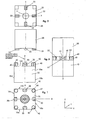
- FIG. 1 is a block-like tool or workpiece 10 shown in side view and top view.
- the tool or workpiece 10 may be, for example, an electrode for an erosion machine.
- the tool or workpiece 10 has four side surfaces 10a, 10b, 10c and 10d and a top 10e, which serves as a reference surface or end face.
- the top 10e is parallel to an area spanned by the coordinates Y and X of a rectangular coordinate system. Perpendicular to these coordinates Y and X is the coordinate Z.
- both centering elements 30 and spacing bolts 40 are seated on the upper side 10e of this tool 10.
- the spacers 40 are located at the four corners of the tool 10.
- the centering elements 30 are disposed between these spacers 40.
- the spacer bolts 40 have a planar top 42, so that a holder 20, which is connected to a machine tool, for example a Senkerodiermaschine, here can rest flat.
- a clamping bolt 60 In the middle of the tool 10 sits a clamping bolt 60, which is screwed for example for this purpose in a corresponding hole.
- Such a holder 20 is in FIG. 2 shown in side view and top view.
- This holder 20 is also designed block-like. However, the holder 20 could also be circular or have any other outer contour. It is only important that the holder 20 has a main surface 23 on which the flat surfaces 42 of the spacer bolts 40 of the tool 10 sit as level as possible. In the embodiment of FIG. 2 are located at the four corners of the holder 20 surface elements 23, which sit exactly to each other in a plane plane corresponding to the XY coordinates.
- the holder 20 has a central bore 21 for receiving the FIG. 1
- the holder 20 has four strips or ridges 22, which serve as receptacles for the centering elements 30. These strips 22 are arranged crosswise to each other. The ridges or strips 22 engage in the U-shaped or prism-shaped recesses 32 of the centering elements 30.
- FIG. 3 the tool or workpiece 10 is shown mounted on the holder 20. It can be clearly seen that the flat top sides 42 of the spacer bolts 40 on the Placed surfaces 23 of the holder 20, wherein the strips or ridges 22 of the holder 20 engage in the centering elements 30.
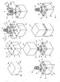
- FIG. 4 is shown in the upper left, the tool 10, for example an electrode, which is not yet suitable to be clamped on a machine tool, for example, a Senkerodiermaschine.
- the bottom right the same tool 10 is shown with inserted centering elements 30, spacers 40 and clamping bolt 60, as it can be clamped to a machine tool.
- the manufacturing path of the tool 10 is in FIG. 4 from top left to bottom right.
- the already known reference numerals will continue to be used for the same parts.
- the same coordinate system XYZ continues to be used.
- a relatively large, central bore 11 is introduced into the tool 10 for receiving a known clamping bolt 60.
- the bore 11 is preferably a screw hole.
- holes 13, preferably screw holes, are incorporated for receiving the abovementioned spacer bolts 40.
- the centering elements 30 and spacer bolts 40 are inserted into the bores 12 and 13 provided for this purpose.
- the spacers 40 are in the holes 13 z. B. screwed.
- the spacers 40 on a threaded pin 41, which cooperates with the thread in the bore 13.
- the standoffs 40 are suitably screwed into the holes 13 with a wrench.
- the spacers 40 are tightened with a predetermined torque.
- the planar surfaces 42 of the spacer bolts 40 are all ideally mounted on a common plane, which is clamped parallel to the coordinates XY when correctly mounted. In the central bore 11 of the clamping bolt 60 is inserted or screwed.
- the centering elements 30 each have a lower plug-in part 31 which can be inserted into the bores 12.
- this plug-in part 31 of each centering element 30 is added to a widened portion, wherein ideally the transition from the male part 31 to this widened gate, which has a U-shaped or prism-shaped recess 32, is rectangular, so that the centering element 30 well on the front side 10e of the tool 10 can sit.
- the holes 12 in the tool 10 are made slightly larger than the diameter of the plug-in parts 31 of the centering elements 30, so that the centering elements 30 after insertion into the corresponding holes 12 are still rotatable in the circumferential direction and slightly displaceable in the XY direction.
- 12 is used when inserting the male parts 31 of the centering elements 30 in the holes.
- some adhesive is dropped before inserting the plug-in parts 31 into the holes 12.
- a threadlocking adhesive can be used as an adhesive.
- FIG. 4 bottom left both the clamping screw 60 and the spacer bolts 40 and the centering elements 30 are shown inserted into the tool 10. It should be noted that the adhesive is not yet cured and therefore the centering elements 30 are still movable, that is rotatable and displaceable.
- a precisely crafted holder 20 for example a reference holder, provided whose ridges or strips 22 are placed accurately.
- This holder 20 is placed on the coarse pre-aligned centering elements 30.
- the strips 22 begin to engage in the recesses 32 of the centering elements 30. Due to the U-shaped or prism-shaped configuration of the recesses 32, the centering elements 30 align themselves slowly with increasing settling of the holder 20 in the direction of the workpiece 10 exactly. As soon as the holder 20 is seated on the flat surfaces 42 of the spacer bolts 40, the lowest position of the holder 20 is reached. It is then waited until the adhesive hardens. This can take a few minutes, for example. After the adhesive has cured, the reference holder 20 can be removed because the centering elements 30 are aligned on the one hand exactly and on the other hand can no longer be twisted or moved due to the curing of the adhesive. In order for a tool 10 is provided, which has in this way exactly aligned centering elements 30, so that the tool 10 can be clamped on the machine tool.
Landscapes
- Engineering & Computer Science (AREA)
- Mechanical Engineering (AREA)
- Chemical & Material Sciences (AREA)
- Chemical Kinetics & Catalysis (AREA)
- Electrochemistry (AREA)
- Jigs For Machine Tools (AREA)
Description
Die Erfindung betrifft eine Vorrichtung zum Positionieren eines Werkzeugs oder Werkstücks, wie z. B. einer Elektrode, auf eine Werkzeugmaschine, wie z. B. einer Erodiermaschine, und ein Werkzeug oder Werkstück gemäß dem Oberbegriff des Anspruchs 1 sowie ein Verfahren zur Positionierung eines solchen Werkzeuges oder Werkstückes auf eine Werkzeugmaschine.The invention relates to a device for positioning a tool or workpiece, such. B. an electrode on a machine tool, such. As an eroding machine, and a tool or workpiece according to the preamble of claim 1 and a method for positioning such a tool or workpiece on a machine tool.
Eine solche Vorrichtung ist z. B. aus der
Solche Vorrichtungen und Verfahren sind hinlänglich bekannt und beispielsweise von der Anmelderin in den offengelegten Patentanmeldungen
Bei der
Die in
Weitere Vorrichtungen zum Positionieren von Werkstücken oder Werkzeugen sind z. B. in
Bei den bekannten Positioniervorrichtungen ist es notwendig, dass das Werkzeug bzw. Werkstück und der Halter exakt zueinander ausgerichtet sind. Hierfür müssen zwangsweise die einzelnen Aufnahmen bzw. Aufnahmeeinrichtungen am Werkstück exakt positioniert werden. Dies ist aufwändig und kostenintensiv. Darüber hinaus zeichnen sich die bisher bekannten Vorrichtungen durch einen verhältnismäßig hohen Platzbedarf aus.In the known positioning devices, it is necessary that the tool or workpiece and the holder are aligned exactly with each other. For this purpose, the individual recordings or recording devices must be forcibly positioned on the workpiece. This is complicated and costly. In addition, the previously known devices are characterized by a relatively large footprint.
Der vorliegenden Erfindung liegt die Aufgabe zugrunde, eine Vorrichtung zum Positionieren eines Werkzeugs oder Werkstücks an einer Werkzeugmaschine sowie ein Verfahren hierfür anzugeben, das sich durch eine einfache Anwendung auszeichnet und dennoch eine hochpräzise Justage des Werkstückes oder Werkzeuges an der Werkzeugmaschine erlaubt. Zusätzlich soll der notwendige Bauraum reduziert werden.The present invention has for its object to provide a device for positioning a tool or workpiece on a machine tool and a method thereof, which is characterized by a simple application and yet allows a high-precision adjustment of the workpiece or tool on the machine tool. In addition, the necessary space is to be reduced.
Diese Aufgabe wird für die Vorrichtung durch die Merkmale des Anspruchs 1 und für das Verfahren durch die Merkmale des Anspruchs 16 gelöst.This object is achieved for the device by the features of claim 1 and for the method by the features of claim 16.
Die Erfindung beruht im Wesentlichen darauf, dass die Zentrierelemente am Werkzeug oder Werkstück als separate Teile eingesetzt und durch besondere Haltemittel dort fixiert und damit dauerhaft gehalten sind.The invention is essentially based on the fact that the centering elements on the tool or workpiece as separate parts used and fixed there by special holding means and thus permanently.
Das Verfahren zur Positionierung eines Werkzeugs oder Werkstücks, wie z. B. einer Elektrode, an einer Werkzeugmaschine, wie z. B. einer Senkerodiermaschine, weist die Verfahrensschritte des Anspruchs 16 auf.The method for positioning a tool or workpiece, such. B. an electrode on a machine tool, such. B. a Senkerodiermaschine, comprises the method steps of claim 16.
Die grundlegende Idee besteht also darin, die Zentrierelemente am Werkzeug oder Werkstück als separate Teile einzusetzen, wobei diese separaten Teile noch etwas beweglich sind und erst anschließend durch geeignete Haltemittel dafür gesorgt wird, dass die Zentrierelemente dauerhaft und richtig fixiert sind. Im einfachsten Fall können die Haltemittel Klebemittel sein. Es ist aber auch denkbar, dass die Zentrierelemente in den Verfahren durch andere Mittel dauerhaft fixiert werden, beispielsweise durch Verspannen, Verpressen, Festklemmen oder dergleichen. Es muss lediglich gewährleistet sein, dass zu Beginn des Einsetzens die Zentrierelemente am Werkzeug oder Werkstück zunächst noch etwas beweglich sind und erst anschließend dauerhaft fixiert werden. Das dauerhafte Fixieren der Zentrierelemente erfolgt durch Aufsetzen des Werkzeugs oder Werkstücks mit eingesetzten, noch beweglichen Zentrierelementen auf einen Halter, der als Referenzhalter ausgebildet sein kann oder bereits am Werkzeug befestigt ist. Bei Aufsetzen des Werkzeuges oder Werkstückes auf den Halter bzw. Referenzhalter können sich die Zentrierelemente dank ihrer noch möglichen Beweglichkeit in die durch den Halter oder Referenzhalter bestimmte, exakte Position ausrichten, also z. B. verdrehen und/oder verschieben. Die so ausgerichteten Zentrierelemente werden nach ihrem exakten Ausrichten dann dauerhaft fixiert, z. B. dadurch, dass diese in der ausgerichteten Position festgeklebt werden.The basic idea is therefore to use the centering on the tool or workpiece as separate parts, these separate parts are still somewhat mobile and only then is ensured by suitable holding means that the centering elements are permanently and properly fixed. In the simplest case, the holding means may be adhesives. However, it is also conceivable that the centering elements are permanently fixed in the process by other means, for example by bracing, pressing, clamping or the like. It only has to be ensured that, at the beginning of insertion, the centering elements on the tool or workpiece are initially somewhat mobile and only then permanently fixed. The permanent fixing of the centering takes place by placing the tool or workpiece with inserted, still moving centering on a holder that may be formed as a reference holder or is already attached to the tool. When placing the tool or workpiece on the holder or reference holder, the centering elements can align thanks to their still possible mobility in the determined by the holder or reference holder, exact position, ie z. B. twist and / or move. The thus aligned centering elements are then permanently fixed after their exact alignment, z. B. in that they are glued in the aligned position.
In einer Ausführungsform der erfindungsgemäßen Vorrichtung weist der Halter der Werkzeugmaschine oder ein entsprechender Referenzhalter Aufnahmen für die Zentrierelemente auf. Diese Aufnahmen des Halters können als von einer Hauptfläche des Halters hervorspringende Grate, Leisten oder Rollen bzw. Kugeln ausgebildet sein, welche z. B. im rechten Winkel zueinander stehen. Geeignete Zentrierelemente verfügen über nutförmige Ausnehmungen, die in diese Grate, Leisten, Kugeln oder Rollen eingreifen. Diese Ausnehmungen in den Zentrierelementen, können z. B. prismenförmig, u-förmig oder v-förmig ausgebildet sein.In one embodiment of the device according to the invention, the holder of the machine tool or a corresponding reference holder has receptacles for the centering elements. These recordings of the holder can be designed as protruding from a main surface of the holder burrs, strips or rollers or balls, which z. B. at right angles to each other. Suitable centering elements have groove-shaped recesses which engage in these ridges, strips, balls or rollers. These recesses in the centering elements, z. B. prismatic, U-shaped or V-shaped.
Es hat sich als zweckmäßig herausgestellt, vier Zentrierelemente vorzusehen, die im Winkel von 90° zueinander um eine Mittenachse des Werkzeugs oder Werkstücks zueinander versetzt angeordnet sind.It has proven to be expedient to provide four centering elements which are at an angle of 90 ° to each other around a Center axis of the tool or workpiece are arranged offset from one another.
Wenn die als Grate oder Leisten ausgebildeten Aufnahmen des Halters von einer Mittenachse weg versetzt angeordnet sind, ist es notwendig, dass die Zentrierelemente im gleichen Abstand zur Mittenachse des Werkzeugs oder Werkstücks angeordnet sind.If the receptacles of the holder designed as ridges or strips are arranged offset from a center axis, it is necessary for the centering elements to be arranged at the same distance from the center axis of the tool or workpiece.
In der Erfindung ist vorgesehen, dass für die Zentrierelemente Bohrungen im Werkstück oder Werkzeug vorhanden sind, in die die Zentrierelemente eingesteckt werden. Hierfür weist jedes Zentrierelement ein Steckteil auf zum Einstecken in die Bohrung sowie ein sich an das Steckteil anschließendes, im Durchmesser breiter ausgebildetes Greifteil. Das Greifteil eines Zentrierelementes ist, wie bereits erwähnt, z. B. mit einer prismenförmigen Ausnehmung versehen, welche in die hervorspringenden Grate oder Leisten des Halters eingreifen.In the invention it is provided that bores are present in the workpiece or tool for the centering, in which the centering elements are inserted. For this purpose, each centering a plug-in part for insertion into the bore and a subsequent to the male part, wider in diameter trained gripping part. The gripping part of a centering element, as already mentioned, z. B. provided with a prism-shaped recess which engage in the protruding ridges or strips of the holder.
Es ist zweckmäßig, dass auf dem Werkzeug oder Werkstück Abstandsbolzen angeordnet sind, durch welche der axiale Abstand vom Werkzeug oder Werkstück zum Halter festgelegt ist. Vorzugsweise sind die Abstandsbolzen lösbar am Werkzeug oder Werkstück angeordnet, z. B. durch Verschrauben. Um eine möglichst plane Auflagefläche zu gewährleisten, weisen die Abstandsbolzen plane Oberseiten auf, auf denen der Halter aufsitzen kann.It is expedient that distance bolts are arranged on the tool or workpiece, by which the axial distance from the tool or workpiece is fixed to the holder. Preferably, the spacer bolts are detachably mounted on the tool or workpiece, for. B. by screwing. In order to ensure the most level possible support surface, the spacers have flat top sides on which the holder can sit.
Die erfindungsgemäße Vorrichtung und das erfindungsgemäße Verfahren zum Positionieren eines Werkzeugs oder Werkstücks an einer Werkzeugmaschine wird nachfolgend im Zusammenhang mit Figuren näher erläutert. Es zeigen:
- Figur 1
- ein Werkstück, z. B. eine Elektrode, in Seitenansicht und Draufsicht,
- Figur 2
- einen Halter, wie er an einer Werkzeugmaschine befestigt sein kann, in Draufsicht und Seitenansicht,
- Figur 3
- den Halter von
Figur 1 und das Werkstück vonFigur 2 im zusammengesteckten Zustand, und - Figur 4
- verschiedene zeitliche Stationen beim Positionieren des Werkstückes auf den Halter nach dem erfindungsgemäßen Verfahren.
- FIG. 1
- a workpiece, for. B. an electrode, in side view and plan view,
- FIG. 2
- a holder, as it may be attached to a machine tool, in plan view and side view,
- FIG. 3
- the holder of
FIG. 1 and the workpiece ofFIG. 2 in the assembled state, and - FIG. 4
- various time stations when positioning the workpiece on the holder according to the inventive method.
In den Figuren bezeichnen, sofern nicht anders angegeben, gleiche Bezugszeichen gleiche Teile mit gleicher Bedeutung.In the figures, unless otherwise indicated, like reference numerals designate like parts with the same meaning.
In
Die Oberseite 10e liegt parallel zu einer Fläche, die durch die Koordinaten Y und X eines rechtwinkligen Koordinatensystems aufgespannt ist. Senkrecht zu diesen Koordinaten Y und X befindet sich die Koordinate Z.The top 10e is parallel to an area spanned by the coordinates Y and X of a rectangular coordinate system. Perpendicular to these coordinates Y and X is the coordinate Z.
Auf der Oberseite 10e dieses Werkzeuges 10 sitzen in noch näher zu erläuternder Art und Weise sowohl Zentrierelemente 30 als auch Abstandsbolzen 40. Wie aus der Draufsicht auf die Oberseite 10e von
Ein solcher Halter 20 ist in
Im Ausführungsbeispiel von
In
Es versteht sich, dass für ein präzises Ausrichten des Werkzeuges 10 auf dem Halter 20 ein korrekter Sitz der Zentrierelemente 30 erforderlich ist. Wie ein solcher korrekter Sitz der Zentrierelemente und deren Ausrichtung erreicht werden kann, wird anhand der Darstellung von
In
Ausgehend von dem in
Die Bohrungen 12 dienen zur Aufnahme der Zentrierelemente 30. Hierfür weisen die Zentrierelemente 30 jeweils ein unteres Steckteil 31 auf, das in die Bohrungen 12 eingesetzt werden kann. An dieses Steckteil 31 jedes Zentrierelements 30 fügt sich ein verbreiterter Abschnitt an, wobei idealer Weise der Übergang vom Steckteil 31 zu diesem verbreiterten Anschnitt, der eine U-förmige oder prismenförmige Ausnehmung 32 aufweist, rechtwinklig ist, damit das Zentrierelement 30 gut auf der Stirnseite 10e des Werkzeuges 10 aufsitzen kann. Die Bohrungen 12 im Werkzeug 10 sind etwas größer gestaltet als der Durchmesser der Steckteile 31 der Zentrierelemente 30, so dass die Zentrierelemente 30 nach dem Einstecken in die entsprechenden Bohrungen 12 noch in Umfangsrichtung verdrehbar sowie etwas in XY-Richtung verschiebbar sind.For this purpose, the centering
Wie in
In
Um die Zentrierelemente 30 in ihre endgültige Lage zu bringen, wird ein exakt gearbeiteter Halter 20, zum Beispiel ein Referenzhalter, zur Verfügung gestellt, dessen Grate oder Leisten 22 exakt platziert sind. Dieser Halter 20 wird auf die grob vorausgerichteten Zentrierelemente 30 aufgesetzt. Unter grob ausgerichtet ist dabei zu verstehen, dass die U-förmigen beziehungsweise prismenförmigen Ausnehmungen 32 der Zentrierelemente 30 bereits in etwa so ausgerichtet sind, dass die Leisten 22 in diese Ausnehmungen 32 der Zentrierelemente 30 eingreifen können.In order to bring the centering
Beim Absenken des Halters 20 in Richtung Werkzeug 10 beginnen die Leisten 22 in die Ausnehmungen 32 der Zentrierelemente 30 einzugreifen. Auf Grund der U-förmigen oder prismenförmigen Gestaltung der Ausnehmungen 32 richten sich die Zentrierelemente 30 langsam bei zunehmendem Absetzen des Halters 20 in Richtung Werkstück 10 exakt aus. Sobald der Halter 20 auf die planen Oberflächen 42 der Abstandsbolzen 40 aufsitzt, ist die tiefste Position des Halters 20 erreicht. Es wird dann so lange gewartet, bis der Kleber aushärtet. Dies kann zum Beispiel wenige Minuten dauern. Nachdem der Kleber ausgehärtet ist, kann der Referenzhalter 20 abgenommen werden, weil die Zentrierelemente 30 einerseits exakt ausgerichtet sind und andererseits auf Grund des Aushärtens des Klebemittels nicht mehr verdreht oder verschoben werden können. Damit ist aber ein Werkzeug 10 bereitgestellt, das auf diese Art und Weise exakt ausgerichtete Zentrierelemente 30 aufweist, so dass das Werkzeug 10 auf die Werkzeugmaschine gespannt werden kann.When lowering the
- 1010
- Werkzeug, Werkstück, ElektrodeTool, workpiece, electrode
- 10a10a
- SeitenwandSide wall
- 10b10b
- SeitenwandSide wall
- 10c10c
- SeitenwandSide wall
- 10d10d
- SeitenwandSide wall
- 10e10e
- Referenzfläche/StirnflächeReference surface / front surface
- 1111
- zentrale Bohrungcentral hole
- 1212
- Bohrung für ZentrierelementeBore for centering elements
- 1313
- Bohrung für AbstandsbolzenBore for spacer bolts
- 2020
- Halterholder
- 2121
- Bohrungdrilling
- 2222
- Aufnahmeadmission
- 2323
- Hauptflächemain area
- 3030
- Zentrierelementcentering
- 3131
- Steckteilmale member
- 3232
- prismenförmige Ausnehmungprism-shaped recess
- 3333
- flache Wandungflat wall
- 3535
- Greifteilgripping part
- 4040
- AbstandsbolzenStandoffs
- 4141
- GewindestiftSet screw
- 4242
- plane Oberseiteplane top
- 6060
- Spannbolzenclamping bolt
- 7070
- Referenzhalterreference holders
- ZZ
- Mittenachsemid-axis
- XX
- Richtungdirection
- YY
- Richtungdirection
Claims (18)
- An apparatus for positioning a tool or a workpiece (10) on a machine tool with a holding means (20) which is connected to the machine tool, and tool or workpiece, wherein the tool or the workpiece (10) has bores (12) for receiving centring elements and has a central tensioning bolt (60) and centring elements (30) with an insertion part (31) which are connected as separate parts to the tool or the workpiece (10) in a stationary manner, wherein the holding means (20) has a central bore (11) for receiving the tensioning bolt (60), characterized in that the bores (12) for the centring elements are made slightly larger than the insertion parts (31) of the centring elements (30) in order to permit alignment of the centring elements (30) in the bores, the centring elements (30) are held in a fixed and stationarily connected manner on the tool or the workpiece (10) by adhesives, and spacer pins (40) are arranged on the tool or the workpiece (10).
- An apparatus according to claim 1, characterized in that the tool or the workpiece (10) is an electrode which is capable of being positioned on a spark erosion machine.
- An apparatus according to claim 1 or 2, characterized in that the receiving means (22) are designed in the form of projecting elements, in particular ridges, strips or rolls.
- An apparatus according to any one of claims 1 to 3, characterized in that four centring elements (30) are provided which are arranged offset with respect to one another at an angle of 90° with respect to one another abcut a central axis (Z) of the tool or the workpiece (10).
- An apparatus according to claim 4, characterized in that the centring elements (30) are situated at an equal distance in each case from the central axis (Z) of the tool or the workpiece (10).
- An apparatus according to any one of claims 1 to 5, characterized in that the tool or the workpiece (10) has provided in it bores (12) for the centring elements (30), into which the centring elements (30) are capable of being inserted, wherein each centring element (30) has an insertion part (31) for insertion into the bore (12) as well as a gripping part (35) adjoining the insertion part (31) and made wider in diameter, wherein the gripping part (35) of a centring element (30) has a prismatic recess (32) which engages in the projecting receiving means (22) of the holding means (20).
- An apparatus according to claim 6, characterized in that the gripping part (35) of a centring element (30) has two flat walls (33) arranged parallel to each other on the outer side of the centring element (30).
- An apparatus according to claim 7, characterized in that the tool or the workpiece (10) has lateral walls (10a, 10b), and a flat wall (33) of a centring pin (30) rests on the same plane as a lateral wall (10a, 10b) of the tool or the workpiece (10) when the centring pin (30) is correctly positioned.
- An apparatus according to any one of claims 1 to 8, characterized in that spacer pins (40), by which the axial distance of the tool or the workpiece (10) from the reference holding means (20) is fixed, are arranged on the tool or the workpiece (10).
- An apparatus according to claim 9, characterized in that the spacer pins (40) are arranged on the tool or the workpiece (10) in a detachable manner.
- An apparatus according to claim 10, characterized in that the spacer pins (40) are screwed into the tool or the workpiece (10).
- An apparatus according to any one of claims 10 or 11, characterized in that the spacer pins (40) have plane top sides (42).
- An apparatus according to any one of claims 1 to 12, characterized in that the tool or the workpiece (10) has a central bore (11) in which a tensioning bolt (60) is mounted.
- An apparatus according to any one of claims 1 to 13, characterized in that a reference holding means (20) is provided which has four receiving means (22) for the centring elements (30) of the workpiece or the tool (10).
- An apparatus according to any one of claims 1 to 14, characterized in that the receiving means (22) are centring stubs.
- A method of positioning a tool or a workpiece (10) on a machine tool with the following method steps:- making available a reference holding means (20) with receiving means (22) for centring elements (30) which are fixed to a tool or a workpiece (10),- making available a tool or a workpiece (10) with a central bore (11) for receiving a tensioning bolt (60) and with bores (12) for receiving centring elements (30),- inserting the tensioning bolt (60) into the central bore (11),- inserting the centring elements (30) into the bores (12) whilst using holding means, wherein the centring elements (30) are still movable,- positioning the tool or the workpiece (10) together with the inserted centring elements (30) on the reference holding means (20), wherein the centring elements (30) engage in the receiving means (22) of the reference holding means (20) and are aligned there during the positioning,- permanently fixing the centring elements (30),- removing the tool or the workpiece (10) from the reference holding means (20) and subsequently clamping it in the holding means of the machine tool.
- A method according to claim 16, characterized in that the centring elements (30) are already aligned manually beforehand during the insertion into the bores (12) of the tool or the workpiece (10).
- A method according to claim 16 or 17, characterized in that the holding means are adhesives, wherein the permanent fixing of the centring elements (30) is carried out by curing the adhesive.
Applications Claiming Priority (2)
| Application Number | Priority Date | Filing Date | Title |
|---|---|---|---|
| DE200610054660 DE102006054660B4 (en) | 2006-11-17 | 2006-11-17 | Device and method for positioning a tool or workpiece on a machine tool |
| PCT/EP2007/009608 WO2008058655A1 (en) | 2006-11-17 | 2007-11-06 | Device and method for positioning a tool or workpiece on a machine tool |
Publications (2)
| Publication Number | Publication Date |
|---|---|
| EP2101948A1 EP2101948A1 (en) | 2009-09-23 |
| EP2101948B1 true EP2101948B1 (en) | 2014-05-14 |
Family
ID=39102989
Family Applications (1)
| Application Number | Title | Priority Date | Filing Date |
|---|---|---|---|
| EP07819627.6A Active EP2101948B1 (en) | 2006-11-17 | 2007-11-06 | Device and method for positioning a tool or workpiece on a machine tool |
Country Status (3)
| Country | Link |
|---|---|
| EP (1) | EP2101948B1 (en) |
| DE (1) | DE102006054660B4 (en) |
| WO (1) | WO2008058655A1 (en) |
Families Citing this family (4)
| Publication number | Priority date | Publication date | Assignee | Title |
|---|---|---|---|---|
| DE102010011947A1 (en) * | 2010-02-17 | 2011-08-18 | Illinois Tool Works Inc., Ill. | Connection element for forming an interface between two detachably connectable parts of a machine tool and method for producing such a connection element |
| CH703777A2 (en) * | 2010-09-14 | 2012-03-15 | Parotec Ag | A device for position-defined clamping of an object. |
| DE102012111548B4 (en) | 2012-11-28 | 2014-07-10 | Hirschmann Gmbh | Device for positioning a tubular workpiece |
| CN115780858A (en) * | 2022-11-23 | 2023-03-14 | 佛山市禅城燃气有限公司 | Pipeline tapping device |
Family Cites Families (11)
| Publication number | Priority date | Publication date | Assignee | Title |
|---|---|---|---|---|
| JPS5928738Y2 (en) * | 1979-02-06 | 1984-08-18 | 株式会社ソディック | Electrode mounting device |
| EP0111092B2 (en) * | 1982-10-18 | 1992-11-25 | Erowa AG | Coupling device |
| JPS60238245A (en) * | 1984-05-11 | 1985-11-27 | Katsuhiro Yoshie | Block jig device |
| DE4101378A1 (en) * | 1991-01-18 | 1992-07-23 | Erowa Ag | Fine setter for mutual positioning of two appts. parts joined together - uses intermediate adjuster with reception guide surfaces having faces in parallel with reference plane |
| DE4116103A1 (en) * | 1991-05-17 | 1992-11-19 | Hirschmann Gmbh | Coupling for tool or part holding mechanisms - has square cross=section with cylindrical rollers positioned along diagonals to locate in slots in tool holder |
| DE4213770C1 (en) * | 1992-04-27 | 1993-12-23 | Hirschmann Gmbh | Device for positioning a tool or workpiece on a machine tool |
| DE4341743C2 (en) * | 1993-12-08 | 1998-01-29 | Emil Stark | Clamping plate for a clamping device with retractable nipple and method for producing the clamping plate |
| DE29511543U1 (en) * | 1995-07-18 | 1996-11-21 | Campro Tooling Ab | Jig |
| DE59705344D1 (en) * | 1996-06-17 | 2001-12-20 | Certa Ag Reinach | Clamping device and device for position-defined clamping of a tool or workpiece |
| DE19649898B4 (en) * | 1996-12-02 | 2007-09-06 | System 3R International Ab | Machining head for a workpiece processing machine |
| DE19907100B4 (en) * | 1999-02-19 | 2004-02-05 | Hirschmann Gmbh | Device for positioning a tool or workpiece on a machine tool |
-
2006
- 2006-11-17 DE DE200610054660 patent/DE102006054660B4/en active Active
-
2007
- 2007-11-06 EP EP07819627.6A patent/EP2101948B1/en active Active
- 2007-11-06 WO PCT/EP2007/009608 patent/WO2008058655A1/en active Application Filing
Also Published As
| Publication number | Publication date |
|---|---|
| WO2008058655A1 (en) | 2008-05-22 |
| DE102006054660B4 (en) | 2009-07-30 |
| EP2101948A1 (en) | 2009-09-23 |
| DE102006054660A1 (en) | 2008-05-21 |
Similar Documents
| Publication | Publication Date | Title |
|---|---|---|
| DE19900292C2 (en) | Universal clamping device and method for positioning and clamping for connecting rods | |
| WO2007059742A1 (en) | Method for introducing and anchoring at least one connecting element into and in a workpiece and device for carrying out said method | |
| EP3219437A1 (en) | Workpiece holder device and method for mounting a workpiece in a workpiece holding device | |
| EP0753368B1 (en) | Clamping device for precise relative fixation of two pieces | |
| EP2745980B1 (en) | Method for the thermal joining of non-circular function components on a shaft | |
| DE102010008187A1 (en) | Tool for cutting material processing and method for aligning cutting inserts in such a tool | |
| EP2101948B1 (en) | Device and method for positioning a tool or workpiece on a machine tool | |
| DE3808210C2 (en) | ||
| DE4300344A1 (en) | ||
| DE3737672A1 (en) | HOLDING DEVICE | |
| EP2219811B1 (en) | Apparatus for chucking a work carrier on a chuck which can be fixed to a machine tool | |
| WO2016071351A1 (en) | Clamping device | |
| EP0275923A2 (en) | Clamping device for work pieces | |
| EP2925488A1 (en) | Device for positioning a tubular workpiece, in particular an injection nozzle | |
| EP0263476A2 (en) | Method for aligning a pallet on a machine tool table, and aligning piece therefor | |
| DE102010022577A1 (en) | Universal clamping apparatus for use with automatic machine tool fixing e.g. proto-type small workpiece, has pin engaged in recesses of engagement portion in locking condition of apparatus, and holder locked in deviate position | |
| DE3439040A1 (en) | Device for connecting a toolholder to a toolholder fixture | |
| DE19739460C1 (en) | Rapid change mounting for machine tool components | |
| AT506831B1 (en) | METHOD FOR CALIBRATING BEARING BUSHES | |
| CH622453A5 (en) | ||
| EP2006634B1 (en) | Device to hold components, in particular sheet metal components for vehicle body work, for measuring in a reference position | |
| EP2743018B1 (en) | Quick clamping device for a tool | |
| AT505991B1 (en) | TEMPLATE FOR RIPENING AND TRANSFERRING MASS ON AND FOR INTRODUCING SURFACES IN SURFACES OF COMPONENTS | |
| AT505361B1 (en) | TOOL HOLDERS AND METHOD FOR ORIENTING TOOL MOUNTS AT THE TOOL HOLDER | |
| DE19705687C2 (en) | Process for the high-precision production of workpiece plates, in particular for the high-precision machining of the front and back of workpiece plates |
Legal Events
| Date | Code | Title | Description |
|---|---|---|---|
| PUAI | Public reference made under article 153(3) epc to a published international application that has entered the european phase |
Free format text: ORIGINAL CODE: 0009012 |
|
| 17P | Request for examination filed |
Effective date: 20090604 |
|
| AK | Designated contracting states |
Kind code of ref document: A1 Designated state(s): AT BE BG CH CY CZ DE DK EE ES FI FR GB GR HU IE IS IT LI LT LU LV MC MT NL PL PT RO SE SI SK TR |
|
| 17Q | First examination report despatched |
Effective date: 20091028 |
|
| DAX | Request for extension of the european patent (deleted) | ||
| GRAP | Despatch of communication of intention to grant a patent |
Free format text: ORIGINAL CODE: EPIDOSNIGR1 |
|
| INTG | Intention to grant announced |
Effective date: 20140106 |
|
| GRAS | Grant fee paid |
Free format text: ORIGINAL CODE: EPIDOSNIGR3 |
|
| GRAA | (expected) grant |
Free format text: ORIGINAL CODE: 0009210 |
|
| AK | Designated contracting states |
Kind code of ref document: B1 Designated state(s): AT BE BG CH CY CZ DE DK EE ES FI FR GB GR HU IE IS IT LI LT LU LV MC MT NL PL PT RO SE SI SK TR |
|
| REG | Reference to a national code |
Ref country code: GB Ref legal event code: FG4D Free format text: NOT ENGLISH |
|
| REG | Reference to a national code |
Ref country code: AT Ref legal event code: REF Ref document number: 667863 Country of ref document: AT Kind code of ref document: T Effective date: 20140615 |
|
| REG | Reference to a national code |
Ref country code: IE Ref legal event code: FG4D Free format text: LANGUAGE OF EP DOCUMENT: GERMAN |
|
| REG | Reference to a national code |
Ref country code: DE Ref legal event code: R096 Ref document number: 502007013125 Country of ref document: DE Effective date: 20140626 |
|
| REG | Reference to a national code |
Ref country code: CH Ref legal event code: NV Representative=s name: R.A. EGLI AND CO, PATENTANWAELTE, CH |
|
| REG | Reference to a national code |
Ref country code: NL Ref legal event code: VDEP Effective date: 20140514 |
|
| REG | Reference to a national code |
Ref country code: LT Ref legal event code: MG4D |
|
| PG25 | Lapsed in a contracting state [announced via postgrant information from national office to epo] |
Ref country code: IS Free format text: LAPSE BECAUSE OF FAILURE TO SUBMIT A TRANSLATION OF THE DESCRIPTION OR TO PAY THE FEE WITHIN THE PRESCRIBED TIME-LIMIT Effective date: 20140914 Ref country code: GR Free format text: LAPSE BECAUSE OF FAILURE TO SUBMIT A TRANSLATION OF THE DESCRIPTION OR TO PAY THE FEE WITHIN THE PRESCRIBED TIME-LIMIT Effective date: 20140815 Ref country code: CY Free format text: LAPSE BECAUSE OF FAILURE TO SUBMIT A TRANSLATION OF THE DESCRIPTION OR TO PAY THE FEE WITHIN THE PRESCRIBED TIME-LIMIT Effective date: 20140514 Ref country code: FI Free format text: LAPSE BECAUSE OF FAILURE TO SUBMIT A TRANSLATION OF THE DESCRIPTION OR TO PAY THE FEE WITHIN THE PRESCRIBED TIME-LIMIT Effective date: 20140514 Ref country code: LT Free format text: LAPSE BECAUSE OF FAILURE TO SUBMIT A TRANSLATION OF THE DESCRIPTION OR TO PAY THE FEE WITHIN THE PRESCRIBED TIME-LIMIT Effective date: 20140514 |
|
| PG25 | Lapsed in a contracting state [announced via postgrant information from national office to epo] |
Ref country code: PL Free format text: LAPSE BECAUSE OF FAILURE TO SUBMIT A TRANSLATION OF THE DESCRIPTION OR TO PAY THE FEE WITHIN THE PRESCRIBED TIME-LIMIT Effective date: 20140514 Ref country code: SE Free format text: LAPSE BECAUSE OF FAILURE TO SUBMIT A TRANSLATION OF THE DESCRIPTION OR TO PAY THE FEE WITHIN THE PRESCRIBED TIME-LIMIT Effective date: 20140514 Ref country code: ES Free format text: LAPSE BECAUSE OF FAILURE TO SUBMIT A TRANSLATION OF THE DESCRIPTION OR TO PAY THE FEE WITHIN THE PRESCRIBED TIME-LIMIT Effective date: 20140514 Ref country code: LV Free format text: LAPSE BECAUSE OF FAILURE TO SUBMIT A TRANSLATION OF THE DESCRIPTION OR TO PAY THE FEE WITHIN THE PRESCRIBED TIME-LIMIT Effective date: 20140514 |
|
| PG25 | Lapsed in a contracting state [announced via postgrant information from national office to epo] |
Ref country code: PT Free format text: LAPSE BECAUSE OF FAILURE TO SUBMIT A TRANSLATION OF THE DESCRIPTION OR TO PAY THE FEE WITHIN THE PRESCRIBED TIME-LIMIT Effective date: 20140915 |
|
| PG25 | Lapsed in a contracting state [announced via postgrant information from national office to epo] |
Ref country code: RO Free format text: LAPSE BECAUSE OF FAILURE TO SUBMIT A TRANSLATION OF THE DESCRIPTION OR TO PAY THE FEE WITHIN THE PRESCRIBED TIME-LIMIT Effective date: 20140514 Ref country code: SK Free format text: LAPSE BECAUSE OF FAILURE TO SUBMIT A TRANSLATION OF THE DESCRIPTION OR TO PAY THE FEE WITHIN THE PRESCRIBED TIME-LIMIT Effective date: 20140514 Ref country code: EE Free format text: LAPSE BECAUSE OF FAILURE TO SUBMIT A TRANSLATION OF THE DESCRIPTION OR TO PAY THE FEE WITHIN THE PRESCRIBED TIME-LIMIT Effective date: 20140514 Ref country code: CZ Free format text: LAPSE BECAUSE OF FAILURE TO SUBMIT A TRANSLATION OF THE DESCRIPTION OR TO PAY THE FEE WITHIN THE PRESCRIBED TIME-LIMIT Effective date: 20140514 Ref country code: DK Free format text: LAPSE BECAUSE OF FAILURE TO SUBMIT A TRANSLATION OF THE DESCRIPTION OR TO PAY THE FEE WITHIN THE PRESCRIBED TIME-LIMIT Effective date: 20140514 |
|
| REG | Reference to a national code |
Ref country code: DE Ref legal event code: R097 Ref document number: 502007013125 Country of ref document: DE |
|
| PG25 | Lapsed in a contracting state [announced via postgrant information from national office to epo] |
Ref country code: NL Free format text: LAPSE BECAUSE OF FAILURE TO SUBMIT A TRANSLATION OF THE DESCRIPTION OR TO PAY THE FEE WITHIN THE PRESCRIBED TIME-LIMIT Effective date: 20140514 |
|
| PLBE | No opposition filed within time limit |
Free format text: ORIGINAL CODE: 0009261 |
|
| STAA | Information on the status of an ep patent application or granted ep patent |
Free format text: STATUS: NO OPPOSITION FILED WITHIN TIME LIMIT |
|
| 26N | No opposition filed |
Effective date: 20150217 |
|
| PG25 | Lapsed in a contracting state [announced via postgrant information from national office to epo] |
Ref country code: IT Free format text: LAPSE BECAUSE OF FAILURE TO SUBMIT A TRANSLATION OF THE DESCRIPTION OR TO PAY THE FEE WITHIN THE PRESCRIBED TIME-LIMIT Effective date: 20140514 |
|
| REG | Reference to a national code |
Ref country code: DE Ref legal event code: R097 Ref document number: 502007013125 Country of ref document: DE Effective date: 20150217 |
|
| PG25 | Lapsed in a contracting state [announced via postgrant information from national office to epo] |
Ref country code: MC Free format text: LAPSE BECAUSE OF FAILURE TO SUBMIT A TRANSLATION OF THE DESCRIPTION OR TO PAY THE FEE WITHIN THE PRESCRIBED TIME-LIMIT Effective date: 20140514 Ref country code: LU Free format text: LAPSE BECAUSE OF FAILURE TO SUBMIT A TRANSLATION OF THE DESCRIPTION OR TO PAY THE FEE WITHIN THE PRESCRIBED TIME-LIMIT Effective date: 20141106 Ref country code: BE Free format text: LAPSE BECAUSE OF NON-PAYMENT OF DUE FEES Effective date: 20141130 |
|
| GBPC | Gb: european patent ceased through non-payment of renewal fee |
Effective date: 20141106 |
|
| PG25 | Lapsed in a contracting state [announced via postgrant information from national office to epo] |
Ref country code: SI Free format text: LAPSE BECAUSE OF FAILURE TO SUBMIT A TRANSLATION OF THE DESCRIPTION OR TO PAY THE FEE WITHIN THE PRESCRIBED TIME-LIMIT Effective date: 20140514 |
|
| REG | Reference to a national code |
Ref country code: IE Ref legal event code: MM4A |
|
| REG | Reference to a national code |
Ref country code: FR Ref legal event code: ST Effective date: 20150731 |
|
| PG25 | Lapsed in a contracting state [announced via postgrant information from national office to epo] |
Ref country code: IE Free format text: LAPSE BECAUSE OF NON-PAYMENT OF DUE FEES Effective date: 20141106 Ref country code: GB Free format text: LAPSE BECAUSE OF NON-PAYMENT OF DUE FEES Effective date: 20141106 |
|
| PG25 | Lapsed in a contracting state [announced via postgrant information from national office to epo] |
Ref country code: FR Free format text: LAPSE BECAUSE OF NON-PAYMENT OF DUE FEES Effective date: 20141201 |
|
| PG25 | Lapsed in a contracting state [announced via postgrant information from national office to epo] |
Ref country code: BG Free format text: LAPSE BECAUSE OF FAILURE TO SUBMIT A TRANSLATION OF THE DESCRIPTION OR TO PAY THE FEE WITHIN THE PRESCRIBED TIME-LIMIT Effective date: 20140514 |
|
| PG25 | Lapsed in a contracting state [announced via postgrant information from national office to epo] |
Ref country code: HU Free format text: LAPSE BECAUSE OF FAILURE TO SUBMIT A TRANSLATION OF THE DESCRIPTION OR TO PAY THE FEE WITHIN THE PRESCRIBED TIME-LIMIT; INVALID AB INITIO Effective date: 20071106 Ref country code: MT Free format text: LAPSE BECAUSE OF FAILURE TO SUBMIT A TRANSLATION OF THE DESCRIPTION OR TO PAY THE FEE WITHIN THE PRESCRIBED TIME-LIMIT Effective date: 20140514 |
|
| REG | Reference to a national code |
Ref country code: DE Ref legal event code: R082 Ref document number: 502007013125 Country of ref document: DE Representative=s name: WESTPHAL, MUSSGNUG & PARTNER PATENTANWAELTE MI, DE Ref country code: DE Ref legal event code: R081 Ref document number: 502007013125 Country of ref document: DE Owner name: CARL HIRSCHMANN GMBH, DE Free format text: FORMER OWNER: HIRSCHMANN GMBH, 78737 FLUORN-WINZELN, DE |
|
| REG | Reference to a national code |
Ref country code: CH Ref legal event code: PFA Owner name: CARL HIRSCHMANN AG, DE Free format text: FORMER OWNER: HIRSCHMANN GMBH, DE Ref country code: CH Ref legal event code: PK Free format text: BERICHTIGUNG INHABER |
|
| REG | Reference to a national code |
Ref country code: AT Ref legal event code: HC Ref document number: 667863 Country of ref document: AT Kind code of ref document: T Owner name: CARL HIRSCHMANN GMBH., DE Effective date: 20200304 |
|
| PGFP | Annual fee paid to national office [announced via postgrant information from national office to epo] |
Ref country code: TR Payment date: 20221101 Year of fee payment: 16 Ref country code: DE Payment date: 20221219 Year of fee payment: 16 Ref country code: AT Payment date: 20221117 Year of fee payment: 16 |
|
| PGFP | Annual fee paid to national office [announced via postgrant information from national office to epo] |
Ref country code: CH Payment date: 20221124 Year of fee payment: 16 |