EP0263476A2 - Procédé d'alignement d'une palette sur une table d'une machine-outil et pièce d'alignement à cet effet - Google Patents
Procédé d'alignement d'une palette sur une table d'une machine-outil et pièce d'alignement à cet effet Download PDFInfo
- Publication number
- EP0263476A2 EP0263476A2 EP87114535A EP87114535A EP0263476A2 EP 0263476 A2 EP0263476 A2 EP 0263476A2 EP 87114535 A EP87114535 A EP 87114535A EP 87114535 A EP87114535 A EP 87114535A EP 0263476 A2 EP0263476 A2 EP 0263476A2
- Authority
- EP
- European Patent Office
- Prior art keywords
- cylinder part
- alignment
- machine tool
- groove guide
- alignment segment
- Prior art date
- Legal status (The legal status is an assumption and is not a legal conclusion. Google has not performed a legal analysis and makes no representation as to the accuracy of the status listed.)
- Withdrawn
Links
Images


Classifications
-
- B—PERFORMING OPERATIONS; TRANSPORTING
- B23—MACHINE TOOLS; METAL-WORKING NOT OTHERWISE PROVIDED FOR
- B23Q—DETAILS, COMPONENTS, OR ACCESSORIES FOR MACHINE TOOLS, e.g. ARRANGEMENTS FOR COPYING OR CONTROLLING; MACHINE TOOLS IN GENERAL CHARACTERISED BY THE CONSTRUCTION OF PARTICULAR DETAILS OR COMPONENTS; COMBINATIONS OR ASSOCIATIONS OF METAL-WORKING MACHINES, NOT DIRECTED TO A PARTICULAR RESULT
- B23Q3/00—Devices holding, supporting, or positioning work or tools, of a kind normally removable from the machine
- B23Q3/18—Devices holding, supporting, or positioning work or tools, of a kind normally removable from the machine for positioning only
-
- B—PERFORMING OPERATIONS; TRANSPORTING
- B23—MACHINE TOOLS; METAL-WORKING NOT OTHERWISE PROVIDED FOR
- B23Q—DETAILS, COMPONENTS, OR ACCESSORIES FOR MACHINE TOOLS, e.g. ARRANGEMENTS FOR COPYING OR CONTROLLING; MACHINE TOOLS IN GENERAL CHARACTERISED BY THE CONSTRUCTION OF PARTICULAR DETAILS OR COMPONENTS; COMBINATIONS OR ASSOCIATIONS OF METAL-WORKING MACHINES, NOT DIRECTED TO A PARTICULAR RESULT
- B23Q1/00—Members which are comprised in the general build-up of a form of machine, particularly relatively large fixed members
- B23Q1/25—Movable or adjustable work or tool supports
- B23Q1/44—Movable or adjustable work or tool supports using particular mechanisms
- B23Q1/48—Movable or adjustable work or tool supports using particular mechanisms with sliding pairs and rotating pairs
- B23Q1/4804—Movable or adjustable work or tool supports using particular mechanisms with sliding pairs and rotating pairs a single rotating pair followed perpendicularly by a single sliding pair
Definitions
- the invention relates to a method according to the preamble of claim 1 and an alignment segment for performing this method.
- a method of this type is known from DE-GM 73 14 053. This known method is used to align workpieces or clamping devices for workpieces on a machine tool table. Alignment segments with an upstanding cylinder part are used in the grooves of the machine tool table, and the workpiece is placed on these cylinder parts with an end face.
- This known alignment method is no longer accurate enough if a mold plate with standard system holes for standard parts is to be aligned on a machine tool table.
- the mounting holes for the frame columns of the machine tool, the so-called system holes of the mold plate are precisely standardized in size and arrangement. However, inaccuracies between the system bores on the one hand and the end faces of the molding plate are inevitable due to the production.
- the aim of the invention is to significantly simplify the alignment of a system plate with system bores on a machine tool table while achieving maximum accuracy.
- a particularly important advantage of the method according to the invention is the fact that it is not only by inserting the alignment segments anchored in the groove An exact alignment of the mold plate is achieved very quickly in the system bores, but moreover an absolute position assurance, in particular also rotation lock of the mold plate, is also provided for all further machining operations, so that the previously common adjustments for recovering an exact alignment are completely eliminated.
- the method according to the invention can basically be used with any machine tool. It is only necessary for the machine tool table to be made in a groove design. This is practically the case with all embodiments of machine tools.
- the invention further relates to an alignment segment for performing the method according to the invention, with a cylinder part and a groove guide part, which is characterized by the characterizing features of claim 2. Since the mold plates to be clamped are extremely heavy and therefore the correct insertion of the groove guide part into the associated groove cannot be easily observed, an Allen key must be inserted from above into the polygonal opening of the cylinder part provided and the alignment segment rotated until the groove guide part is in the groove can collapse.
- a threaded bore can be provided according to claim 4, in which a corresponding external thread pulling tool is inserted from above, so that the alignment segment can be pulled up out of the system bore after tightening the pulling tool.
- each alignment segment can have a spacer.
- spacer strips can be dispensed with. The correct distance is already ensured by inserting the alignment segments.
- alignment segments with spacers must also be used in at least one or two further system bores. However, it is not necessary with these additional alignment segments that they are also provided with groove guide parts, but with them the spacers can simply rest on the machine tool table (claim 7).
- the embodiment according to claim 6 is particularly easy to handle, since the alignment segment also Cylinder part and groove guide part can be inserted into the system bore from above and pulled out upwards, despite the spacer loosely sitting on it, while the spacer ring remains clamped between the machine tool table and the mold plate.
- the turning of the alignment segments when inserting can also be carried out with less effort if the spacer ring does not have to rotate with it and a large frictional force arises between the same and the molding plate.
- the groove guide part can be fastened interchangeably in the cylinder part. Different groove guide parts and cylinder parts can then be combined very easily.
- the groove guide part is screwed into a corresponding recess in the cylinder part or the spacer.
- the recess accommodating the groove guide part can be arranged slightly eccentrically, so that groove deviations can be compensated for easily by slightly rotating the cylinder part.
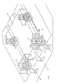
- a molding plate 12 with standardized system bores 14 and 16 is placed on the machine table, generally designated 10 and only partially shown, of a machine tool of any type, which is otherwise not shown.
- the machine table 10 has grooves 18 of conventional construction.
- an alignment segment is inserted into the system bores 14 and a groove 18.
- the alignment segment 20 consists of a cylinder part 22 seated snugly in the system bore 14 and a groove guide part 24 protruding axially from the cylinder part 22, which slidably engages in the groove 18 with an exact fit.
- An Allen key can be inserted from above into a polygonal opening 26 provided on the upper side of the cylinder part 22 the system bore 14 is inserted into the cylinder part 22 and the alignment segment is thereby rotated into the correct position.
- clamping of the mold plate 12, which is precisely aligned in this way, on the machine tool table 10 can be carried out with any clamping devices, not shown, e.g. Clamping claws take place without impairing the precise alignment.
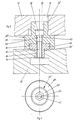
- the machine table has 10 grooves 18 ⁇ and 18 ⁇ .
- the mold plate 12 corresponds to the mold plate shown in FIG. 1.
- the embodiment of the alignment segments 20 ⁇ used in this arrangement has, in addition to the cylinder part 22 ⁇ , a cylindrical spacer 28 integral therewith, the diameter of which is larger than the diameter of the cylinder part 22 ⁇ .
- the groove guide part 24 der which engages in the groove 18 ⁇ and is to be explained in more detail below, is fastened to the spacer 28.
- the cylinder part 22 ⁇ of the alignment segment 20 ⁇ in the system bore 14 can be actuated from above into a polygonal opening 26 by inserting an Allen key.
- the form plate 12 is held at a defined distance from the machine table 10 by the spacer 28.
- a cylindrical insert part 36 of the groove guide part 24 ⁇ is inserted flush.
- An inserted through the polygonal opening 26 and held by a polygonal head 38 in this rotationally fixed screw bolt 40 is by a conn ß bore 42 of the spacer 28 is screwed by means of a thread 44 into an internally threaded bore 46 of the groove guide member 24 ⁇ .
- the cylinder part 22 ⁇ and the groove guide part 24 ⁇ thus form a unit which is firmly connected to the screw bolt 40, namely the alignment segment 20 ⁇ , which, like the alignment segment 20 of the first embodiment, can be used on the one hand in the mold plate 12 and on the other hand in the grooves 18 ⁇ of the machine tool table 10.
- the precise alignment of the molding plate 12 in the direction given by the groove 18 ⁇ can also take place extremely quickly and exactly, the alignment segment 20 ⁇ being able to be adapted to different groove dimensions by exchanging the groove guide parts 24 ⁇ .
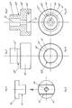
- Cylinder parts 22 ⁇ of a third embodiment of the alignment segment according to the invention are inserted into the system bores 16 only from below.
- Spacers 28 ⁇ corresponding to the spacers 28 of the second embodiment according to FIG. 3 are integrally connected to the cylinder parts 22 ⁇ , which ensure a parallel position of the mold plate 12 with respect to the machine tool table 10.
- the exact shape of the alignment segments 20 ⁇ can be seen from FIGS. 7 and 8.
- a fourth embodiment of the alignment segment 20 erfindungsdorfen according to FIGS. 9 and 10 which essentially corresponds to the embodiment according to FIG. 3, only the axis 48 of the recess 34 ⁇ on the underside of the spacer 28 ⁇ is opposite the axis 50 of the cylindrical part 22 ′′′ slightly offset eccentrically.
- An insert part (not shown) of a corresponding groove guide part is inserted into the recess 34 ⁇ .
- FIGS. 11 and 12 The embodiment shown in FIGS. 11 and 12 is particularly preferred. It differs from the embodiment shown in FIGS. 3 and 4 essentially in that the cylinder part 22 ⁇ of this embodiment of the alignment segment 20 ⁇ with the groove 18 slidingly engaging groove guide part 24 ⁇ is made in one piece and the spacer inserted between the machine tool table 10 and the mold plate 12 28 ′′′ is designed as a loose ring on the outside of the cylinder part 22 ⁇ .
- a polygonal opening 26teils is also recessed into the top of the cylinder part 22 ⁇ , into which an Allen key (not shown) can be inserted from above through the system bore 14 for rotating the link consisting of the cylinder part 22 ⁇ and the groove guide part 24 ⁇ . When rotating this link, the annular spacer 28 ′′′ can remain untwisted, so that there are significantly lower frictional forces.
- the spacer 28 ′′′ can be omitted entirely in this embodiment, which results in a similar embodiment as in FIG. 1.
Applications Claiming Priority (2)
| Application Number | Priority Date | Filing Date | Title |
|---|---|---|---|
| DE3634118 | 1986-10-07 | ||
| DE19863634118 DE3634118A1 (de) | 1986-10-07 | 1986-10-07 | Ausrichtsegment zum aufspannen einer formplatte auf einem werkzeugmaschinentisch |
Publications (2)
| Publication Number | Publication Date |
|---|---|
| EP0263476A2 true EP0263476A2 (fr) | 1988-04-13 |
| EP0263476A3 EP0263476A3 (fr) | 1989-04-12 |
Family
ID=6311222
Family Applications (1)
| Application Number | Title | Priority Date | Filing Date |
|---|---|---|---|
| EP87114535A Withdrawn EP0263476A3 (fr) | 1986-10-07 | 1987-10-05 | Procédé d'alignement d'une palette sur une table d'une machine-outil et pièce d'alignement à cet effet |
Country Status (2)
| Country | Link |
|---|---|
| EP (1) | EP0263476A3 (fr) |
| DE (2) | DE8627319U1 (fr) |
Cited By (8)
| Publication number | Priority date | Publication date | Assignee | Title |
|---|---|---|---|---|
| EP0357093A2 (fr) * | 1988-09-01 | 1990-03-07 | China National Aero-Technology Import And Export Corp. | Appareil pour l'ajustement des porte-pièces |
| GB2260093A (en) * | 1991-10-04 | 1993-04-07 | Hattori Seiko Co Ltd | Tool for sizing and repairing a band |
| US5208929A (en) * | 1991-10-04 | 1993-05-11 | Kabushiki Kaisha Hattori Seiko | Multiple band sizing and repairing device |
| CN102398163A (zh) * | 2011-10-21 | 2012-04-04 | 河南飞龙(芜湖)汽车零部件有限公司 | 排气管钻侧面丝孔夹具 |
| CN102975072A (zh) * | 2012-11-20 | 2013-03-20 | 惠州智科实业有限公司 | 一种散热器全自动镗孔治具 |
| CN103978386A (zh) * | 2014-06-05 | 2014-08-13 | 赵夫超 | 一种薄板钻孔的手动钻床的固定装置 |
| US20150108311A1 (en) * | 2012-03-23 | 2015-04-23 | Pascal Engineering Corporation | Object positioning and fixing device |
| GB2529473A (en) * | 2014-08-22 | 2016-02-24 | Airbus Operations Ltd | Support device |
Families Citing this family (2)
| Publication number | Priority date | Publication date | Assignee | Title |
|---|---|---|---|---|
| DE4117895A1 (de) * | 1991-05-31 | 1992-12-03 | Hasco Normalien Hasenclever Co | Hoehenzylinder |
| DE4341743C2 (de) * | 1993-12-08 | 1998-01-29 | Emil Stark | Aufspannplatte für eine Spannvorrichtung mit Einzugsnippel und Verfahren zur Herstellung der Aufspannplatte |
Citations (13)
| Publication number | Priority date | Publication date | Assignee | Title |
|---|---|---|---|---|
| US1682472A (en) * | 1926-04-26 | 1928-08-28 | Micro Machine Company | Work-adjusting means |
| US2372716A (en) * | 1944-05-23 | 1945-04-03 | Gerald T Evans | Locating key |
| US2620704A (en) * | 1950-08-31 | 1952-12-09 | Gerald T Evans | Locating key |
| US2696765A (en) * | 1952-03-05 | 1954-12-14 | Joe S Appleton | Fixture key |
| US2707419A (en) * | 1953-08-19 | 1955-05-03 | Jergens Tool Specialty Company | Means for locating fixture plates with respect to the beds or platens of machine tools |
| US2828589A (en) * | 1954-05-28 | 1958-04-01 | Lad L Hercik | Work table support |
| US3336653A (en) * | 1965-02-25 | 1967-08-22 | Ralph B Symons | Adjustable tool positioning and aligning device |
| GB1116152A (en) * | 1963-11-11 | 1968-06-06 | Autodyne Engineering Ltd | Means for locating a workpiece in a required machining position on a faceplate of a lathe, or on the table of a milling machine |
| US3554530A (en) * | 1968-12-05 | 1971-01-12 | Donald E Moore | Tee slot locator |
| US3608886A (en) * | 1969-06-11 | 1971-09-28 | Gary Y Greene | System of digital jigging |
| US3622145A (en) * | 1968-04-19 | 1971-11-23 | Edwin W Glbson | Work-positioning member |
| DE7314053U (de) * | 1973-04-13 | 1973-08-09 | Halder E Maschinen Und Werkzeugfabrik | Richtanschlag |
| DE2736204A1 (de) * | 1977-08-11 | 1979-02-22 | Alfred Wieland | Werkstueckspanntisch fuer werkzeugmaschinen |
Family Cites Families (1)
| Publication number | Priority date | Publication date | Assignee | Title |
|---|---|---|---|---|
| DE2139437B1 (de) * | 1971-08-06 | 1972-10-12 | Siemens AG, 1000 Berlin u 8000 München | Vorrichtung zum gegenseitigen Ausrichten von einander zugeordne ten Maschinenteilen |
-
1986
- 1986-10-07 DE DE19868627319 patent/DE8627319U1/de not_active Expired
- 1986-10-07 DE DE19863634118 patent/DE3634118A1/de active Granted
-
1987
- 1987-10-05 EP EP87114535A patent/EP0263476A3/fr not_active Withdrawn
Patent Citations (13)
| Publication number | Priority date | Publication date | Assignee | Title |
|---|---|---|---|---|
| US1682472A (en) * | 1926-04-26 | 1928-08-28 | Micro Machine Company | Work-adjusting means |
| US2372716A (en) * | 1944-05-23 | 1945-04-03 | Gerald T Evans | Locating key |
| US2620704A (en) * | 1950-08-31 | 1952-12-09 | Gerald T Evans | Locating key |
| US2696765A (en) * | 1952-03-05 | 1954-12-14 | Joe S Appleton | Fixture key |
| US2707419A (en) * | 1953-08-19 | 1955-05-03 | Jergens Tool Specialty Company | Means for locating fixture plates with respect to the beds or platens of machine tools |
| US2828589A (en) * | 1954-05-28 | 1958-04-01 | Lad L Hercik | Work table support |
| GB1116152A (en) * | 1963-11-11 | 1968-06-06 | Autodyne Engineering Ltd | Means for locating a workpiece in a required machining position on a faceplate of a lathe, or on the table of a milling machine |
| US3336653A (en) * | 1965-02-25 | 1967-08-22 | Ralph B Symons | Adjustable tool positioning and aligning device |
| US3622145A (en) * | 1968-04-19 | 1971-11-23 | Edwin W Glbson | Work-positioning member |
| US3554530A (en) * | 1968-12-05 | 1971-01-12 | Donald E Moore | Tee slot locator |
| US3608886A (en) * | 1969-06-11 | 1971-09-28 | Gary Y Greene | System of digital jigging |
| DE7314053U (de) * | 1973-04-13 | 1973-08-09 | Halder E Maschinen Und Werkzeugfabrik | Richtanschlag |
| DE2736204A1 (de) * | 1977-08-11 | 1979-02-22 | Alfred Wieland | Werkstueckspanntisch fuer werkzeugmaschinen |
Cited By (13)
| Publication number | Priority date | Publication date | Assignee | Title |
|---|---|---|---|---|
| EP0357093A2 (fr) * | 1988-09-01 | 1990-03-07 | China National Aero-Technology Import And Export Corp. | Appareil pour l'ajustement des porte-pièces |
| EP0357093A3 (fr) * | 1988-09-01 | 1990-12-05 | China National Aero-Technology Import And Export Corp. | Appareil pour l'ajustement des porte-pièces |
| GB2260093A (en) * | 1991-10-04 | 1993-04-07 | Hattori Seiko Co Ltd | Tool for sizing and repairing a band |
| US5208929A (en) * | 1991-10-04 | 1993-05-11 | Kabushiki Kaisha Hattori Seiko | Multiple band sizing and repairing device |
| US5230132A (en) * | 1991-10-04 | 1993-07-27 | Kabushiki Kaisha Hattori Seiko | Method of use for a multiple bond sizing and repairing device |
| GB2260093B (en) * | 1991-10-04 | 1994-11-16 | Hattori Seiko Co Ltd | Tool for sizing and repairing a band |
| CN102398163A (zh) * | 2011-10-21 | 2012-04-04 | 河南飞龙(芜湖)汽车零部件有限公司 | 排气管钻侧面丝孔夹具 |
| CN102398163B (zh) * | 2011-10-21 | 2015-07-15 | 河南飞龙(芜湖)汽车零部件有限公司 | 排气管钻侧面丝孔夹具 |
| US20150108311A1 (en) * | 2012-03-23 | 2015-04-23 | Pascal Engineering Corporation | Object positioning and fixing device |
| US9440322B2 (en) * | 2012-03-23 | 2016-09-13 | Pascal Engineering Cooperation | Object positioning and fixing device |
| CN102975072A (zh) * | 2012-11-20 | 2013-03-20 | 惠州智科实业有限公司 | 一种散热器全自动镗孔治具 |
| CN103978386A (zh) * | 2014-06-05 | 2014-08-13 | 赵夫超 | 一种薄板钻孔的手动钻床的固定装置 |
| GB2529473A (en) * | 2014-08-22 | 2016-02-24 | Airbus Operations Ltd | Support device |
Also Published As
| Publication number | Publication date |
|---|---|
| DE8627319U1 (fr) | 1989-08-17 |
| DE3634118C2 (fr) | 1988-09-22 |
| DE3634118A1 (de) | 1988-04-21 |
| EP0263476A3 (fr) | 1989-04-12 |
Similar Documents
| Publication | Publication Date | Title |
|---|---|---|
| DE3934495C1 (fr) | ||
| DE2339873C2 (de) | Anordnung zum Einstellen und Befestigen eines ein Schneidplättchen tragenden Blocks in einer nutförmigen Aufnahme im Werkzeugkörper eines spanabhebenden Werkzeugs | |
| EP0602204B1 (fr) | Element intermediaire pour dispositifs de serrage sur plaques a matrice de trous de machine-outil | |
| DE3733849C1 (de) | Maschinenschraubstock mit Kraftverstaerker | |
| DE3317916A1 (de) | Fraeswerkzeug | |
| EP1620219A1 (fr) | Outil de forage | |
| DE4341743C2 (de) | Aufspannplatte für eine Spannvorrichtung mit Einzugsnippel und Verfahren zur Herstellung der Aufspannplatte | |
| EP0263476A2 (fr) | Procédé d'alignement d'une palette sur une table d'une machine-outil et pièce d'alignement à cet effet | |
| EP0310967B1 (fr) | Dispositif de serrage | |
| EP0275923A2 (fr) | Dispositif de serrage de pièces | |
| DE3137878C2 (de) | Überlastsicherung für den Vorschubantrieb an einer Werkzeugmaschine | |
| DE2746958C2 (de) | Anlegeelement für eine Wendeschneidplatte | |
| EP0007077A1 (fr) | Porte-outil à changement rapide, notamment pour tour automatique longitudinal ou machines-outils analogues | |
| EP0873815A2 (fr) | Serrage d'une pièce par boulon de serrage | |
| EP2743018B1 (fr) | Dispositif de serrage rapide d'outil | |
| EP1314516B1 (fr) | Elément de fixation | |
| EP2743017B1 (fr) | Dispositif de serrage rapide d'outil | |
| DE2150558C3 (de) | Bohrkopf | |
| DE19917484A1 (de) | Befestigung eines Einzugsnippels an einem Werkstück oder einer Trägerplatte | |
| DE3432942A1 (de) | Haltevorrichtung fuer elektroden an funkenerosionsmaschinen | |
| DE3828239C2 (fr) | ||
| DE19705687C2 (de) | Verfahren zur hochgenauen Herstellung von Werkstückplatten, insbesondere zur hochgenauen Bearbeitung von Vorder- und Rückseite von Werkstückplatten | |
| EP0470410B1 (fr) | Réceptacle pour pièce, réalisé en métal, plastique ou en bois | |
| DE3625901A1 (de) | Vorrichtung zur befestigung der leisten an einem automaten fuer die herstellung von schuhen | |
| DE4012468A1 (de) | Vorrichtung zum spannen von werkstuecken auf einem spanntisch |
Legal Events
| Date | Code | Title | Description |
|---|---|---|---|
| PUAI | Public reference made under article 153(3) epc to a published international application that has entered the european phase |
Free format text: ORIGINAL CODE: 0009012 |
|
| AK | Designated contracting states |
Kind code of ref document: A2 Designated state(s): AT BE CH DE ES FR GB IT LI NL SE |
|
| PUAL | Search report despatched |
Free format text: ORIGINAL CODE: 0009013 |
|
| AK | Designated contracting states |
Kind code of ref document: A3 Designated state(s): AT BE CH DE ES FR GB IT LI NL SE |
|
| 17P | Request for examination filed |
Effective date: 19891002 |
|
| 17Q | First examination report despatched |
Effective date: 19900108 |
|
| STAA | Information on the status of an ep patent application or granted ep patent |
Free format text: STATUS: THE APPLICATION IS DEEMED TO BE WITHDRAWN |
|
| 18D | Application deemed to be withdrawn |
Effective date: 19910522 |