EP2101631B1 - Hornhautmessgerät und anwendungsverfahren dafür - Google Patents
Hornhautmessgerät und anwendungsverfahren dafür Download PDFInfo
- Publication number
- EP2101631B1 EP2101631B1 EP07855209.8A EP07855209A EP2101631B1 EP 2101631 B1 EP2101631 B1 EP 2101631B1 EP 07855209 A EP07855209 A EP 07855209A EP 2101631 B1 EP2101631 B1 EP 2101631B1
- Authority
- EP
- European Patent Office
- Prior art keywords
- slit
- light
- apertures
- cornea
- subsystem
- Prior art date
- Legal status (The legal status is an assumption and is not a legal conclusion. Google has not performed a legal analysis and makes no representation as to the accuracy of the status listed.)
- Active
Links
- 238000005259 measurement Methods 0.000 title claims description 36
- 238000000034 method Methods 0.000 title claims description 14
- 210000004087 cornea Anatomy 0.000 claims description 58
- 238000003384 imaging method Methods 0.000 claims description 14
- 239000000758 substrate Substances 0.000 claims description 10
- 238000012545 processing Methods 0.000 claims description 7
- 238000011144 upstream manufacturing Methods 0.000 claims description 4
- 210000002159 anterior chamber Anatomy 0.000 description 4
- 239000011521 glass Substances 0.000 description 2
- 239000002184 metal Substances 0.000 description 2
- 238000001356 surgical procedure Methods 0.000 description 2
- 241001137901 Centropomus undecimalis Species 0.000 description 1
- 239000006117 anti-reflective coating Substances 0.000 description 1
- 238000010276 construction Methods 0.000 description 1
- 238000005530 etching Methods 0.000 description 1
- 210000001061 forehead Anatomy 0.000 description 1
- 210000003128 head Anatomy 0.000 description 1
- 238000005286 illumination Methods 0.000 description 1
- 238000012986 modification Methods 0.000 description 1
- 230000004048 modification Effects 0.000 description 1
- 230000003287 optical effect Effects 0.000 description 1
- 239000005361 soda-lime glass Substances 0.000 description 1
- 239000000126 substance Substances 0.000 description 1
- 238000013519 translation Methods 0.000 description 1
- 230000000007 visual effect Effects 0.000 description 1
Images


Classifications
-
- A—HUMAN NECESSITIES
- A61—MEDICAL OR VETERINARY SCIENCE; HYGIENE
- A61B—DIAGNOSIS; SURGERY; IDENTIFICATION
- A61B3/00—Apparatus for testing the eyes; Instruments for examining the eyes
- A61B3/10—Objective types, i.e. instruments for examining the eyes independent of the patients' perceptions or reactions
- A61B3/107—Objective types, i.e. instruments for examining the eyes independent of the patients' perceptions or reactions for determining the shape or measuring the curvature of the cornea
-
- A—HUMAN NECESSITIES
- A61—MEDICAL OR VETERINARY SCIENCE; HYGIENE
- A61B—DIAGNOSIS; SURGERY; IDENTIFICATION
- A61B3/00—Apparatus for testing the eyes; Instruments for examining the eyes
- A61B3/10—Objective types, i.e. instruments for examining the eyes independent of the patients' perceptions or reactions
- A61B3/1005—Objective types, i.e. instruments for examining the eyes independent of the patients' perceptions or reactions for measuring distances inside the eye, e.g. thickness of the cornea
-
- A—HUMAN NECESSITIES
- A61—MEDICAL OR VETERINARY SCIENCE; HYGIENE
- A61B—DIAGNOSIS; SURGERY; IDENTIFICATION
- A61B3/00—Apparatus for testing the eyes; Instruments for examining the eyes
- A61B3/10—Objective types, i.e. instruments for examining the eyes independent of the patients' perceptions or reactions
- A61B3/13—Ophthalmic microscopes
- A61B3/135—Slit-lamp microscopes
Definitions
- Ophthalmologists and optometrists would like to have an accurate representation of subjects' eye.
- Such representations include, for example, one or more of a representation of a subject's corneal anterior surface, posterior surface, and corneal thickness and density, as well as anterior chamber profiles. This information may be used to prescribe contact lenses and eye glasses, and to reshape the cornea by surgical procedures or to perform other surgical procedures. Since it is not comfortable to measure these data with physical contact, remote sensing techniques are preferably used to perform the measurements.
- One common technique for obtaining corneal measurement information includes projecting narrow bands of light (commonly referred to as slits or slit beams) onto a patient's cornea at multiple locations across a cornea. For each of the slits, after the light in the slit has been scattered by the cornea, an image of the light is obtained.
- slits narrow bands of light
- an aperture of appropriate shape and size, and a lens are placed in the path of light from a light source such that the light passing through the aperture forms a slit of light on a subject's cornea.
- a single aperture is translated such that the light passing through the aperture at selected times forms the multiple slits.
- aspects of the present invention are directed to eye measurement apparatus having a slit mask defining a plurality of apertures for projecting slits of light onto an eye.
- the apparatus further comprises (F.) a second slit projection subsystem comprising a second light source, (G.) a second mask subsystem disposed in a path of second light from the second slit projection subsystem, comprising a second slit mask defining a second plurality of apertures, (H.) a second movement apparatus adapted to move at least a portion of the second slit projection subsystem, the second movement apparatus configured and arranged such that by moving the portion of the second slit projection subsystem, portions of the second light can be selectively transmitted through an aperture of the second plurality of apertures toward the cornea; and (I.) a second imaging element configured and arranged to image the second plurality of apertures onto the cornea, the image capture subsystem arranged to capture images of the portions of second light after the light impinges on the cornea.
- a second slit projection subsystem comprising a second light source
- G. a second mask subsystem disposed in a path of second light from the second slit projection subsystem, comprising
- the second slit mask is disposed upstream of the first slit mask.
- the slit projection subsystem is configured and arranged to project light from the light source through each of the plurality of apertures defined in first slit mask without moving the light source.
- the plurality of apertures is disposed in a single plane. In some embodiments, the plurality of apertures is formed on a single substrate. In some examples, the plurality of apertures is defined by openings in an opaque layer deposited on the substrate.
- the light source comprises at least one high power LED. In some examples, the light source consists of a single LED.
- the movement apparatus is adapted to translate the at least portion of the slit projection subsystem.
- the light source is adapted to project a slit of light and the movement apparatus is adapted to translate the light source.
- the movement apparatus is adapted to translate the second slit mask.
- the movement apparatus is adapted to rotate the at least portion of the slit projection subsystem.
- Another aspect of the present invention is directed to a method of facilitating measurement of a subject's cornea, comprising: (A.) providing a plurality of apertures, (B.) projecting light toward the plurality of apertures, (C.) moving at least a portion of a slit projector subsystem while maintaining the plurality of apertures in fixed locations to selectively transmit a portion of the light toward the cornea, the portion of the light passing through a selected aperture of the plurality of apertures; and, (D.) imaging the portions of light after the light impinges on the cornea.
- the step of moving comprises translating the at least portion of the slit projection subsystem. In some embodiments, the step of moving comprises rotating the at least portion of the slit projection subsystem.
- the step of moving comprises moving a selection slit. In some examples, the step of moving comprises moving at least one source.
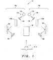
- FIG. 1 is a schematic view of an embodiment of a corneal measurement apparatus 10 according to aspects of the present invention.
- the corneal measurement apparatus is adapted to measure a subject's cornea C.
- the corneal measurement apparatus comprises two slit projection systems 13a, 13b (including light sources 12a and 12b, respectively), two mask subsystems 100a, 100b, and an image capture subsystem 50.
- Mask subsystems 100a and 100b are disposed in the paths of light from slit projection systems 13a and 13b, respectively.
- Slit projection system 13a and mask subsystem 100a are in a first arm 75a of the corneal measurement apparatus and slit projection system 13b and mask subsystem 100b are in a second arm 75b of the corneal measurement apparatus.
- the first arm projects slits of light onto one half of the cornea
- the second arm projects slits of light onto the other half of the cornea.
- the path of each of the projected slits of light may be at a approximately forty-five degree angle to the visual axis of the subject's eye.
- the illustrated embodiment of a measurement apparatus has two arms, in other embodiments, a measurement apparatus may only have a single arm.
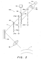
- the arm comprises a mask subsystem comprising a first slit mask 130 defining a plurality of apertures 132 i and a slit projection subsystem comprising a light source 12a and a second slit mask 120 defining a selection aperture 122.
- the arm also comprises a movement apparatus 110 adapted to translate the second mask.
- Second slit mask 120 is configured and arranged such that, by appropriately positioning the second slit mask using the movement apparatus to move the second slit mask relative to the first slit mask, selection aperture 122 selectively transmits portions of the light from source 12a such that light traveling through an aperture of the plurality of apertures 132 i impinges on cornea C.
- the movement apparatus may move the selection aperture in any suitable manner to suitably position the selection aperture.
- the movement apparatus may move any suitable portion of the slit projection subsystem to suitably project a slit of light onto a cornea C. For example, as set forth below, the light source may be moved.
- the second slit mask 120 i.e., the mask including the selection aperture
- the first slit mask i.e., the mask including the plurality of apertures
- the second slit mask 120 can be disposed upstream of the second slit mask.
- light sources 12a and 12b generate the light in which a corresponding mask subsystem is disposed.
- the source projects light from the light sources in a cone of light CN to permit light to be projected through each of the apertures defined in first slit mask 130 without moving the source. That is to say that, in some examples, only the second slit mask 120 is moved. The movement occurs to expose a given one of the plurality of apertures on the first mask 130 to light from a light source.
- the plurality of apertures 132 that provide the slits of light can remain fixed in a given location during the acquisition of the plurality of slit images used to produce a representation of a subject's eye.
- the source is monochromatic and suitably bright.
- an LED or a plurality of LEDs may be used to generate the light.
- a high power LED has been found useful.
- a superluminescent LED is used.
- a not claimed aspect of the invention is directed to a single high power LED configured and arranged to be capable of illuminating the plurality of apertures 132 as the selection aperture is moved.
- the condenser lenses 14a, 14b are illustrated as conventional refractive lenses, any suitable imaging element may be used (e.g., a mirror, holographic element). In some examples, the condenser lens may be omitted.
- the projection system components and first slit mask 130 may be disposed in a Scheimpflug arrangement to obtain a plane of slit images at cornea C. Also, one or more folding mirrors 16a and 16b may be included to direct light onto the cornea, and to achieve an appropriate package shape to fit in a housing (not shown) of the apparatus.
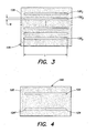
- Slit mask 130 includes a plurality of apertures 132 1 - 132 n .
- the slits are of a same width W and length L and are evenly spaced apart; however, aspects of the invention are not so limited.
- Slit mask 120 includes a single selection aperture formed on a substrate 125.
- the selection aperture is sized to permit light to pass from one of the plurality of apertures to cornea C (shown in FIG. 1 ).
- the size of the selection aperture is larger in width and length than any of the plurality of apertures.
- the selection aperture is also typically small enough such that light is only permitted to pass through a single one of the plurality of apertures and onto cornea C.
- the image capture subsystem 50 is arranged to be able to capture an image of light projected for each of the plurality of apertures after the light impinges on the cornea. It will be appreciated that, to capture of the images to obtain a representation of a cornea, each of the plurality of apertures is selected sequentially by appropriately aligning each aperture with the selection aperture as described above.
- Image capture subsystem 50 may be any suitable conventional imaging device, such as a CCD camera.
- Corneal measurement apparatus 10 also includes an image processing subsystem to convert the images into a single representation of the cornea. Techniques for reconstructing a representation of a subject's cornea once the slit images are obtained are well known and are not described further here. Projection systems as described herein may be used with corneal topographers, corneal profiler apparatus and anterior chamber analyzers.
- Corneal measurement apparatus 10 includes a subject positioning apparatus 60 adapted to maintain a subject's cornea in a location.
- the apparatus may be provided with a chin rest and/or a forehead rest which will fix the location of the subject's head.
- FIG. 5 illustrates further details of another example of an embodiment of one arm 200 of corneal measurement apparatus 10 (shown in FIG. 1 ).
- the arm comprises a mask subsystem comprising first slit mask 130 defining a plurality of apertures 132 i ; and a slit projection subsystem 220 comprising a plurality of light sources 212 1-n (shown in FIG. 6 ).
- subsystem 220 is arranged to project a slit of light without the use of a mask having a selection aperture (e.g., mask 120 having a selection aperture 122 in FIG. 2 ).
- the arm also comprises a movement apparatus 210 adapted to move (e.g., translate) the slit projector subsystem 220, so as to appropriately position the plurality of light sources such that light travels through a selected one of the plurality of apertures 132 i and is focused onto cornea C (e.g., by lens 218).
- a movement apparatus 210 adapted to move (e.g., translate) the slit projector subsystem 220, so as to appropriately position the plurality of light sources such that light travels through a selected one of the plurality of apertures 132 i and is focused onto cornea C (e.g., by lens 218).
- FIG. 6 is a schematic illustration of the further details of the light sources 212 1-n included in the illumination slit projection subsystem.
- the sources may, for example, comprise LEDs disposed on a circuit board to project a long narrow band of light. Any suitable number LEDs may be used. Although, a plurality of sources is shown in the illustrated embodiment, a single elongate source may be used.
- FIG. 7 is a schematic view of another example of a corneal measurement apparatus 700 according to aspects of the present invention.
- the corneal measurement apparatus comprises a slit projection systems 713 (including a light source 712), a mask subsystems 731, and an image capture subsystem 750.
- the mask subsystem is disposed in the path of light from slit projection systems 713.
- the mask subsystem comprises a first slit mask 730 defining a plurality of apertures 732 1-n (shown in FIG. 9 ).
Claims (15)
- Hornhautmessgerät zum Vermessen der Hornhaut eines Patienten, wobei das Gerät aufweist:(A) ein Schlitzprojektion-Subsystem mit einer Lichtquelle (12a);(B) ein Masken-Subsystem (100a), das in einem Lichtpfad der Lichtquelle (12a) angeordnet ist und eine erste Schlitzmaske (130) aufweist, die mehrere Öffnungen (132i) begrenzt, wobei die mehreren Öffnungen (132i) während der Vermessung der Patientenhornhaut ortsfest bleiben;(C) eine Bewegungsvorrichtung (110) zum Bewegen mindestens eines Teils des Schlitzprojektion-Subsystems, wobei die Bewegungsvorrichtung (110) derart konfiguriert und angeordnet ist, dass durch Bewegen des Schlitzprojektion-Subsystems Teile des Lichts selektiv durch eine der mehreren Öffnungen (132i) zur Hornhaut durchgelassen werden können;(D) ein Abbildungselement (14a,14b,18a,18b), das konfiguriert und angeordnet ist, um mindestens eine der mehreren Öffnungen (132i) auf die Hornhaut abzubilden; und(E) ein Bilderfassung-Subsystem (50), das angeordnet ist, um nach Auftreffen des Lichts auf der Hornhaut Bilder der Lichtteile zu erfassen.
- Gerät nach Anspruch 1, wobei das Schlitzprojektion-Subsystem eine zweite Schlitzmaske (120) aufweist, die eine Auswahlöffnung (122) begrenzt und von der Bewegungsvorrichtung (110) bewegbar ist.
- Gerät nach Anspruch 2, wobei die zweite Schlitzmaske (120) vor - bezogen auf die Lichtausbreitungsrichtung - der ersten Schlitzmaske (130) angeordnet ist.
- Gerät nach Anspruch 1, wobei die mehreren Öffnungen (132i) in einer einzigen Ebene angeordnet sind.
- Gerät nach Anspruch 1, wobei die mehreren Öffnungen (132i) auf einem einzigen Substrat gebildet sind.
- Gerät nach Anspruch 1, ferner mit einem Bildverarbeitung-Subsystem, das mit dem Bilderfassung-Subsystem (50) gekoppelt ist und fähig ist, die Bilder in eine Darstellung der Hornhaut zu konvertieren.
- Gerät nach Anspruch 1, wobei die Bewegungsvorrichtung (110) den mindestens einen Teil des Schlitzprojektion-Subsystems verschieben kann.
- Gerät nach Anspruch 7, wobei die Lichtquelle (12a) einen Lichtschlitz projizieren kann und die Bewegungsvorrichtung (110) die Lichtquelle (12a) verschieben kann.
- Gerät nach Anspruch 2, wobei die Bewegungsvorrichtung (110) die zweite Schlitzmaske (120) verschieben kann.
- Gerät nach Anspruch 1, wobei die Bewegungsvorrichtung (110) den mindestens einen Teil des Schlitzprojektion-Subsystems drehen kann.
- Verfahren zur Erleichterung einer Vermessung der Hornhaut eines Patienten mit den folgenden Schritten:(A) Bereitstellen mehrerer Öffnungen (132i);(B) Projizieren von Licht zu den mehreren Öffnungen (132i);(C) Bewegen mindestens eines Teils eines Schlitzprojektion-Subsystems unter Beibehaltung der Position der mehreren Öffnungen (132i), um selektiv einen Teil des Lichts zur Hornhaut durchzulassen, wobei der Teil des Lichts durch eine ausgewählte Öffnung der mehreren Öffnungen (132i) hindurchgeht; und(D) Abbilden der Teile des Lichts nach Auftreffen des Lichts auf der Hornhaut.
- Verfahren nach Anspruch 11, wobei der Bewegungsschritt ein Verschieben des mindestens einen Teils des Schlitzprojektion-Subsystems aufweist.
- Verfahren nach Anspruch 11, wobei der Bewegungsschritt ein Drehen des mindestens einen Teils des Schlitzprojektion-Subsystems aufweist.
- Verfahren nach Anspruch 11, wobei der Bewegungsschritt ein Bewegen eines Auswahlschlitzes (122) aufweist.
- Verfahren nach Anspruch 11, wobei der Abbildungsschritt Bilder erzeugt und das Verfahren ferner aufweist: Verarbeiten der Bilder, um die Bilder in eine Darstellung der Hornhaut zu konvertieren.
Priority Applications (1)
| Application Number | Priority Date | Filing Date | Title |
|---|---|---|---|
| PL07855209T PL2101631T3 (pl) | 2006-12-21 | 2007-12-17 | Urządzenie do pomiaru rogówki i sposób korzystania z tego urządzenia |
Applications Claiming Priority (2)
| Application Number | Priority Date | Filing Date | Title |
|---|---|---|---|
| US11/614,518 US20080151190A1 (en) | 2006-12-21 | 2006-12-21 | Corneal measurment apparatus and a method of using the same |
| PCT/US2007/087747 WO2008079766A1 (en) | 2006-12-21 | 2007-12-17 | Corneal measurement apparatus and a method of using the same |
Publications (2)
| Publication Number | Publication Date |
|---|---|
| EP2101631A1 EP2101631A1 (de) | 2009-09-23 |
| EP2101631B1 true EP2101631B1 (de) | 2015-09-02 |
Family
ID=39415139
Family Applications (1)
| Application Number | Title | Priority Date | Filing Date |
|---|---|---|---|
| EP07855209.8A Active EP2101631B1 (de) | 2006-12-21 | 2007-12-17 | Hornhautmessgerät und anwendungsverfahren dafür |
Country Status (5)
| Country | Link |
|---|---|
| US (2) | US20080151190A1 (de) |
| EP (1) | EP2101631B1 (de) |
| ES (1) | ES2547278T3 (de) |
| PL (1) | PL2101631T3 (de) |
| WO (1) | WO2008079766A1 (de) |
Families Citing this family (18)
| Publication number | Priority date | Publication date | Assignee | Title |
|---|---|---|---|---|
| EP1173790A2 (de) | 1999-03-01 | 2002-01-23 | Boston Innovative Optics, Inc. | Vorrichtung und verfahren zur erhöhung der tiefenschärfe des menschlichen auges |
| US7628810B2 (en) | 2003-05-28 | 2009-12-08 | Acufocus, Inc. | Mask configured to maintain nutrient transport without producing visible diffraction patterns |
| US20050046794A1 (en) | 2003-06-17 | 2005-03-03 | Silvestrini Thomas A. | Method and apparatus for aligning a mask with the visual axis of an eye |
| CA2711438C (en) | 2008-01-08 | 2013-10-01 | Amo Wavefront Sciences Llc | Systems and methods for measuring surface shape |
| JP5355994B2 (ja) * | 2008-11-05 | 2013-11-27 | 株式会社ニデック | 眼科撮影装置 |
| KR101796801B1 (ko) | 2009-08-13 | 2017-11-10 | 아큐포커스, 인크. | 마스크형 안구 내 임플란트 및 렌즈 |
| US10004593B2 (en) | 2009-08-13 | 2018-06-26 | Acufocus, Inc. | Intraocular lens with elastic mask |
| JP6030448B2 (ja) | 2009-08-13 | 2016-11-24 | アキュフォーカス・インコーポレーテッド | 栄養輸送構造物を備えた角膜インレイ |
| WO2011047076A1 (en) * | 2009-10-13 | 2011-04-21 | Acufocus, Inc. | Method and apparatus for centration of an ocular implant |
| US20140098342A1 (en) * | 2011-11-04 | 2014-04-10 | The General Hospital Corporation | System and method for corneal irradiation |
| JP6046160B2 (ja) | 2011-12-02 | 2016-12-14 | アキュフォーカス・インコーポレーテッド | 選択的分光透過性を有する眼科マスク |
| US9204962B2 (en) | 2013-03-13 | 2015-12-08 | Acufocus, Inc. | In situ adjustable optical mask |
| US9427922B2 (en) | 2013-03-14 | 2016-08-30 | Acufocus, Inc. | Process for manufacturing an intraocular lens with an embedded mask |
| CN106999278A (zh) | 2014-11-19 | 2017-08-01 | 阿库福库斯公司 | 用于治疗老视的可断裂掩盖物 |
| EP3359987B1 (de) | 2015-10-05 | 2024-02-28 | AcuFocus, Inc. | Verfahren zum formen von intraokularlinsen |
| US11464625B2 (en) | 2015-11-24 | 2022-10-11 | Acufocus, Inc. | Toric small aperture intraocular lens with extended depth of focus |
| EP3443883B1 (de) * | 2017-08-14 | 2020-07-29 | Carl Zeiss Vision International GmbH | Vorrichtungen und verfahren zur durchführung augenbezogener messungen |
| US11364110B2 (en) | 2018-05-09 | 2022-06-21 | Acufocus, Inc. | Intraocular implant with removable optic |
Family Cites Families (17)
| Publication number | Priority date | Publication date | Assignee | Title |
|---|---|---|---|---|
| JPS55125844A (en) * | 1979-03-20 | 1980-09-29 | Canon Kk | Optic refractometer |
| JPS56132936A (en) * | 1980-03-21 | 1981-10-17 | Tokyo Optical | Eye bottom camera |
| AU716040B2 (en) * | 1993-06-24 | 2000-02-17 | Bausch & Lomb Incorporated | Ophthalmic pachymeter and method of making ophthalmic determinations |
| DE29913603U1 (de) * | 1999-08-04 | 1999-11-25 | Oculus Optikgeraete Gmbh | Spaltprojektor |
| DE29913602U1 (de) * | 1999-08-04 | 1999-11-25 | Oculus Optikgeraete Gmbh | Gerät zur Augenuntersuchung mit einer Scheimpflugkamera und einem Spaltprojektor zur Aufnahme von Schnittbildern eines Auges |
| US7275827B2 (en) * | 2000-04-11 | 2007-10-02 | Benedikt Jean | Selective corneal aberrometry |
| JP3709335B2 (ja) * | 2000-09-28 | 2005-10-26 | 株式会社ニデック | 眼科装置 |
| JP2003047595A (ja) * | 2001-08-06 | 2003-02-18 | Nidek Co Ltd | 眼科撮影装置 |
| US6575573B2 (en) * | 2001-10-17 | 2003-06-10 | Carl Zeiss Ophthalmic Systems, Inc. | Method and apparatus for measuring a corneal profile of an eye |
| JP3978024B2 (ja) * | 2001-12-03 | 2007-09-19 | 株式会社ニデック | 眼科装置及び角膜手術装置 |
| DE20306542U1 (de) * | 2003-04-25 | 2003-08-28 | Oculus Optikgeraete Gmbh | Vorrichtung zur Projektion eines Lichtstrahls |
| KR20060035656A (ko) * | 2003-06-30 | 2006-04-26 | 가부시키가이샤 라이트세이사쿠쇼 | 안굴절력 측정 장치 |
| US7070276B2 (en) * | 2003-12-04 | 2006-07-04 | Rensselaer Polytechnic Institute | Apparatus and method for accommodative stimulation of an eye and simultaneous ipsilateral accommodative imaging |
| US7347549B2 (en) * | 2003-12-10 | 2008-03-25 | Bausch & Lomb Incorporated | Rapid switching slit scan image capture system |
| JP2005237901A (ja) * | 2004-03-01 | 2005-09-08 | Nidek Co Ltd | 眼科装置 |
| EP1738680B1 (de) * | 2005-07-01 | 2011-03-09 | Nidek Co., Ltd. | Augenuntersuchungsgerät |
| JP4987408B2 (ja) * | 2006-09-29 | 2012-07-25 | 株式会社ニデック | 眼科装置 |
-
2006
- 2006-12-21 US US11/614,518 patent/US20080151190A1/en not_active Abandoned
-
2007
- 2007-12-12 US US11/955,001 patent/US7648241B2/en active Active
- 2007-12-17 WO PCT/US2007/087747 patent/WO2008079766A1/en active Application Filing
- 2007-12-17 EP EP07855209.8A patent/EP2101631B1/de active Active
- 2007-12-17 ES ES07855209.8T patent/ES2547278T3/es active Active
- 2007-12-17 PL PL07855209T patent/PL2101631T3/pl unknown
Also Published As
| Publication number | Publication date |
|---|---|
| US20080151190A1 (en) | 2008-06-26 |
| US7648241B2 (en) | 2010-01-19 |
| PL2101631T3 (pl) | 2016-03-31 |
| WO2008079766A1 (en) | 2008-07-03 |
| EP2101631A1 (de) | 2009-09-23 |
| ES2547278T3 (es) | 2015-10-02 |
| US20080212030A1 (en) | 2008-09-04 |
Similar Documents
| Publication | Publication Date | Title |
|---|---|---|
| EP2101631B1 (de) | Hornhautmessgerät und anwendungsverfahren dafür | |
| JP4553578B2 (ja) | 眼科用装置と眼科用測定方法 | |
| JP5756253B2 (ja) | 光コヒーレンス断層法機構を有する外科用顕微鏡システム | |
| US20090096987A1 (en) | Eye Measurement Apparatus and a Method of Using Same | |
| KR100992182B1 (ko) | 안과용 양안 파면 측정 시스템 | |
| JPS6216088B2 (de) | ||
| EA004236B1 (ru) | Система и способ для бесконтактного измерения длины оси, и/или кривизны роговицы, и/или глубины передней камеры глаза предпочтительно для расчета внутриглазных линз (вгл) | |
| JP7167417B2 (ja) | 眼底撮影装置および眼科装置 | |
| JP3916482B2 (ja) | 眼科装置 | |
| US6382794B1 (en) | Method and apparatus for mapping a corneal contour and thickness profile | |
| US7896497B2 (en) | Corneal measurement apparatus having a segmented aperture and a method of using the same | |
| JP4722853B2 (ja) | 眼前部の測定のための装置 | |
| US11089956B2 (en) | Ophthalmologic apparatus and method of controlling the same | |
| EP0337651A1 (de) | Ophthalmologisches Diagnose-Verfahren und Gerät | |
| US3572908A (en) | Apparatus for measuring and recording refractive errors of a patient{3 s eye | |
| JP6095439B2 (ja) | 眼科装置、その制御方法、及びプログラム | |
| JPS6125371B2 (de) | ||
| US11154190B2 (en) | Eye surface topographer | |
| JP3594447B2 (ja) | 眼科装置 | |
| JPH09108185A (ja) | 眼科装置 | |
| JP7279349B2 (ja) | 眼科装置 | |
| US3776620A (en) | Opthalmometer having alternative viewing and measuring systems | |
| JP2022105110A (ja) | 眼科装置 | |
| JPH0554325B2 (de) | ||
| JPS61206422A (ja) | 視野計測装置 |
Legal Events
| Date | Code | Title | Description |
|---|---|---|---|
| PUAI | Public reference made under article 153(3) epc to a published international application that has entered the european phase |
Free format text: ORIGINAL CODE: 0009012 |
|
| 17P | Request for examination filed |
Effective date: 20090716 |
|
| AK | Designated contracting states |
Kind code of ref document: A1 Designated state(s): AT BE BG CH CY CZ DE DK EE ES FI FR GB GR HU IE IS IT LI LT LU LV MC MT NL PL PT RO SE SI SK TR |
|
| DAX | Request for extension of the european patent (deleted) | ||
| 17Q | First examination report despatched |
Effective date: 20111219 |
|
| GRAP | Despatch of communication of intention to grant a patent |
Free format text: ORIGINAL CODE: EPIDOSNIGR1 |
|
| INTG | Intention to grant announced |
Effective date: 20150312 |
|
| GRAS | Grant fee paid |
Free format text: ORIGINAL CODE: EPIDOSNIGR3 |
|
| GRAA | (expected) grant |
Free format text: ORIGINAL CODE: 0009210 |
|
| AK | Designated contracting states |
Kind code of ref document: B1 Designated state(s): AT BE BG CH CY CZ DE DK EE ES FI FR GB GR HU IE IS IT LI LT LU LV MC MT NL PL PT RO SE SI SK TR |
|
| REG | Reference to a national code |
Ref country code: GB Ref legal event code: FG4D |
|
| REG | Reference to a national code |
Ref country code: AT Ref legal event code: REF Ref document number: 746017 Country of ref document: AT Kind code of ref document: T Effective date: 20150915 Ref country code: CH Ref legal event code: EP |
|
| REG | Reference to a national code |
Ref country code: IE Ref legal event code: FG4D |
|
| REG | Reference to a national code |
Ref country code: FR Ref legal event code: PLFP Year of fee payment: 9 |
|
| REG | Reference to a national code |
Ref country code: ES Ref legal event code: FG2A Ref document number: 2547278 Country of ref document: ES Kind code of ref document: T3 Effective date: 20151002 |
|
| REG | Reference to a national code |
Ref country code: DE Ref legal event code: R096 Ref document number: 602007042941 Country of ref document: DE |
|
| REG | Reference to a national code |
Ref country code: AT Ref legal event code: MK05 Ref document number: 746017 Country of ref document: AT Kind code of ref document: T Effective date: 20150902 |
|
| PG25 | Lapsed in a contracting state [announced via postgrant information from national office to epo] |
Ref country code: GR Free format text: LAPSE BECAUSE OF FAILURE TO SUBMIT A TRANSLATION OF THE DESCRIPTION OR TO PAY THE FEE WITHIN THE PRESCRIBED TIME-LIMIT Effective date: 20151203 Ref country code: LT Free format text: LAPSE BECAUSE OF FAILURE TO SUBMIT A TRANSLATION OF THE DESCRIPTION OR TO PAY THE FEE WITHIN THE PRESCRIBED TIME-LIMIT Effective date: 20150902 Ref country code: LV Free format text: LAPSE BECAUSE OF FAILURE TO SUBMIT A TRANSLATION OF THE DESCRIPTION OR TO PAY THE FEE WITHIN THE PRESCRIBED TIME-LIMIT Effective date: 20150902 Ref country code: FI Free format text: LAPSE BECAUSE OF FAILURE TO SUBMIT A TRANSLATION OF THE DESCRIPTION OR TO PAY THE FEE WITHIN THE PRESCRIBED TIME-LIMIT Effective date: 20150902 |
|
| REG | Reference to a national code |
Ref country code: LT Ref legal event code: MG4D Ref country code: NL Ref legal event code: MP Effective date: 20150902 |
|
| PG25 | Lapsed in a contracting state [announced via postgrant information from national office to epo] |
Ref country code: SE Free format text: LAPSE BECAUSE OF FAILURE TO SUBMIT A TRANSLATION OF THE DESCRIPTION OR TO PAY THE FEE WITHIN THE PRESCRIBED TIME-LIMIT Effective date: 20150902 Ref country code: AT Free format text: LAPSE BECAUSE OF FAILURE TO SUBMIT A TRANSLATION OF THE DESCRIPTION OR TO PAY THE FEE WITHIN THE PRESCRIBED TIME-LIMIT Effective date: 20150902 |
|
| PG25 | Lapsed in a contracting state [announced via postgrant information from national office to epo] |
Ref country code: SK Free format text: LAPSE BECAUSE OF FAILURE TO SUBMIT A TRANSLATION OF THE DESCRIPTION OR TO PAY THE FEE WITHIN THE PRESCRIBED TIME-LIMIT Effective date: 20150902 Ref country code: NL Free format text: LAPSE BECAUSE OF FAILURE TO SUBMIT A TRANSLATION OF THE DESCRIPTION OR TO PAY THE FEE WITHIN THE PRESCRIBED TIME-LIMIT Effective date: 20150902 Ref country code: IS Free format text: LAPSE BECAUSE OF FAILURE TO SUBMIT A TRANSLATION OF THE DESCRIPTION OR TO PAY THE FEE WITHIN THE PRESCRIBED TIME-LIMIT Effective date: 20160102 Ref country code: CZ Free format text: LAPSE BECAUSE OF FAILURE TO SUBMIT A TRANSLATION OF THE DESCRIPTION OR TO PAY THE FEE WITHIN THE PRESCRIBED TIME-LIMIT Effective date: 20150902 Ref country code: EE Free format text: LAPSE BECAUSE OF FAILURE TO SUBMIT A TRANSLATION OF THE DESCRIPTION OR TO PAY THE FEE WITHIN THE PRESCRIBED TIME-LIMIT Effective date: 20150902 |
|
| PG25 | Lapsed in a contracting state [announced via postgrant information from national office to epo] |
Ref country code: BE Free format text: LAPSE BECAUSE OF NON-PAYMENT OF DUE FEES Effective date: 20151231 Ref country code: PT Free format text: LAPSE BECAUSE OF FAILURE TO SUBMIT A TRANSLATION OF THE DESCRIPTION OR TO PAY THE FEE WITHIN THE PRESCRIBED TIME-LIMIT Effective date: 20160104 Ref country code: RO Free format text: LAPSE BECAUSE OF FAILURE TO SUBMIT A TRANSLATION OF THE DESCRIPTION OR TO PAY THE FEE WITHIN THE PRESCRIBED TIME-LIMIT Effective date: 20150902 |
|
| REG | Reference to a national code |
Ref country code: DE Ref legal event code: R097 Ref document number: 602007042941 Country of ref document: DE |
|
| PLBE | No opposition filed within time limit |
Free format text: ORIGINAL CODE: 0009261 |
|
| STAA | Information on the status of an ep patent application or granted ep patent |
Free format text: STATUS: NO OPPOSITION FILED WITHIN TIME LIMIT |
|
| PG25 | Lapsed in a contracting state [announced via postgrant information from national office to epo] |
Ref country code: LU Free format text: LAPSE BECAUSE OF FAILURE TO SUBMIT A TRANSLATION OF THE DESCRIPTION OR TO PAY THE FEE WITHIN THE PRESCRIBED TIME-LIMIT Effective date: 20151217 Ref country code: MC Free format text: LAPSE BECAUSE OF FAILURE TO SUBMIT A TRANSLATION OF THE DESCRIPTION OR TO PAY THE FEE WITHIN THE PRESCRIBED TIME-LIMIT Effective date: 20150902 |
|
| REG | Reference to a national code |
Ref country code: CH Ref legal event code: PL |
|
| 26N | No opposition filed |
Effective date: 20160603 |
|
| PG25 | Lapsed in a contracting state [announced via postgrant information from national office to epo] |
Ref country code: SI Free format text: LAPSE BECAUSE OF FAILURE TO SUBMIT A TRANSLATION OF THE DESCRIPTION OR TO PAY THE FEE WITHIN THE PRESCRIBED TIME-LIMIT Effective date: 20150902 Ref country code: DK Free format text: LAPSE BECAUSE OF FAILURE TO SUBMIT A TRANSLATION OF THE DESCRIPTION OR TO PAY THE FEE WITHIN THE PRESCRIBED TIME-LIMIT Effective date: 20150902 |
|
| REG | Reference to a national code |
Ref country code: IE Ref legal event code: MM4A |
|
| PG25 | Lapsed in a contracting state [announced via postgrant information from national office to epo] |
Ref country code: CH Free format text: LAPSE BECAUSE OF NON-PAYMENT OF DUE FEES Effective date: 20151231 Ref country code: LI Free format text: LAPSE BECAUSE OF NON-PAYMENT OF DUE FEES Effective date: 20151231 Ref country code: IE Free format text: LAPSE BECAUSE OF NON-PAYMENT OF DUE FEES Effective date: 20151217 |
|
| REG | Reference to a national code |
Ref country code: FR Ref legal event code: PLFP Year of fee payment: 10 |
|
| PG25 | Lapsed in a contracting state [announced via postgrant information from national office to epo] |
Ref country code: BE Free format text: LAPSE BECAUSE OF FAILURE TO SUBMIT A TRANSLATION OF THE DESCRIPTION OR TO PAY THE FEE WITHIN THE PRESCRIBED TIME-LIMIT Effective date: 20150902 |
|
| PG25 | Lapsed in a contracting state [announced via postgrant information from national office to epo] |
Ref country code: BG Free format text: LAPSE BECAUSE OF FAILURE TO SUBMIT A TRANSLATION OF THE DESCRIPTION OR TO PAY THE FEE WITHIN THE PRESCRIBED TIME-LIMIT Effective date: 20150902 Ref country code: HU Free format text: LAPSE BECAUSE OF FAILURE TO SUBMIT A TRANSLATION OF THE DESCRIPTION OR TO PAY THE FEE WITHIN THE PRESCRIBED TIME-LIMIT; INVALID AB INITIO Effective date: 20071217 |
|
| PG25 | Lapsed in a contracting state [announced via postgrant information from national office to epo] |
Ref country code: CY Free format text: LAPSE BECAUSE OF FAILURE TO SUBMIT A TRANSLATION OF THE DESCRIPTION OR TO PAY THE FEE WITHIN THE PRESCRIBED TIME-LIMIT Effective date: 20150902 |
|
| PG25 | Lapsed in a contracting state [announced via postgrant information from national office to epo] |
Ref country code: MT Free format text: LAPSE BECAUSE OF FAILURE TO SUBMIT A TRANSLATION OF THE DESCRIPTION OR TO PAY THE FEE WITHIN THE PRESCRIBED TIME-LIMIT Effective date: 20150902 Ref country code: TR Free format text: LAPSE BECAUSE OF FAILURE TO SUBMIT A TRANSLATION OF THE DESCRIPTION OR TO PAY THE FEE WITHIN THE PRESCRIBED TIME-LIMIT Effective date: 20150902 |
|
| REG | Reference to a national code |
Ref country code: FR Ref legal event code: PLFP Year of fee payment: 11 |
|
| PGFP | Annual fee paid to national office [announced via postgrant information from national office to epo] |
Ref country code: PL Payment date: 20190918 Year of fee payment: 13 |
|
| PG25 | Lapsed in a contracting state [announced via postgrant information from national office to epo] |
Ref country code: PL Free format text: LAPSE BECAUSE OF NON-PAYMENT OF DUE FEES Effective date: 20201217 |
|
| PGFP | Annual fee paid to national office [announced via postgrant information from national office to epo] |
Ref country code: IT Payment date: 20221122 Year of fee payment: 16 |
|
| PGFP | Annual fee paid to national office [announced via postgrant information from national office to epo] |
Ref country code: ES Payment date: 20230102 Year of fee payment: 16 |
|
| P01 | Opt-out of the competence of the unified patent court (upc) registered |
Effective date: 20230503 |
|
| PGFP | Annual fee paid to national office [announced via postgrant information from national office to epo] |
Ref country code: GB Payment date: 20231121 Year of fee payment: 17 |
|
| PGFP | Annual fee paid to national office [announced via postgrant information from national office to epo] |
Ref country code: FR Payment date: 20231122 Year of fee payment: 17 Ref country code: DE Payment date: 20231121 Year of fee payment: 17 |
|
| PGFP | Annual fee paid to national office [announced via postgrant information from national office to epo] |
Ref country code: ES Payment date: 20240102 Year of fee payment: 17 |