EP2101631B1 - Corneal measurement apparatus and a method of using the same - Google Patents
Corneal measurement apparatus and a method of using the same Download PDFInfo
- Publication number
- EP2101631B1 EP2101631B1 EP07855209.8A EP07855209A EP2101631B1 EP 2101631 B1 EP2101631 B1 EP 2101631B1 EP 07855209 A EP07855209 A EP 07855209A EP 2101631 B1 EP2101631 B1 EP 2101631B1
- Authority
- EP
- European Patent Office
- Prior art keywords
- slit
- light
- apertures
- cornea
- subsystem
- Prior art date
- Legal status (The legal status is an assumption and is not a legal conclusion. Google has not performed a legal analysis and makes no representation as to the accuracy of the status listed.)
- Active
Links
- 238000005259 measurement Methods 0.000 title claims description 36
- 238000000034 method Methods 0.000 title claims description 14
- 210000004087 cornea Anatomy 0.000 claims description 58
- 238000003384 imaging method Methods 0.000 claims description 14
- 239000000758 substrate Substances 0.000 claims description 10
- 238000012545 processing Methods 0.000 claims description 7
- 238000011144 upstream manufacturing Methods 0.000 claims description 4
- 210000002159 anterior chamber Anatomy 0.000 description 4
- 239000011521 glass Substances 0.000 description 2
- 239000002184 metal Substances 0.000 description 2
- 238000001356 surgical procedure Methods 0.000 description 2
- 241001137901 Centropomus undecimalis Species 0.000 description 1
- 239000006117 anti-reflective coating Substances 0.000 description 1
- 238000010276 construction Methods 0.000 description 1
- 238000005530 etching Methods 0.000 description 1
- 210000001061 forehead Anatomy 0.000 description 1
- 210000003128 head Anatomy 0.000 description 1
- 238000005286 illumination Methods 0.000 description 1
- 238000012986 modification Methods 0.000 description 1
- 230000004048 modification Effects 0.000 description 1
- 230000003287 optical effect Effects 0.000 description 1
- 239000005361 soda-lime glass Substances 0.000 description 1
- 239000000126 substance Substances 0.000 description 1
- 238000013519 translation Methods 0.000 description 1
- 230000000007 visual effect Effects 0.000 description 1
Images


Classifications
-
- A—HUMAN NECESSITIES
- A61—MEDICAL OR VETERINARY SCIENCE; HYGIENE
- A61B—DIAGNOSIS; SURGERY; IDENTIFICATION
- A61B3/00—Apparatus for testing the eyes; Instruments for examining the eyes
- A61B3/10—Objective types, i.e. instruments for examining the eyes independent of the patients' perceptions or reactions
- A61B3/107—Objective types, i.e. instruments for examining the eyes independent of the patients' perceptions or reactions for determining the shape or measuring the curvature of the cornea
-
- A—HUMAN NECESSITIES
- A61—MEDICAL OR VETERINARY SCIENCE; HYGIENE
- A61B—DIAGNOSIS; SURGERY; IDENTIFICATION
- A61B3/00—Apparatus for testing the eyes; Instruments for examining the eyes
- A61B3/10—Objective types, i.e. instruments for examining the eyes independent of the patients' perceptions or reactions
- A61B3/1005—Objective types, i.e. instruments for examining the eyes independent of the patients' perceptions or reactions for measuring distances inside the eye, e.g. thickness of the cornea
-
- A—HUMAN NECESSITIES
- A61—MEDICAL OR VETERINARY SCIENCE; HYGIENE
- A61B—DIAGNOSIS; SURGERY; IDENTIFICATION
- A61B3/00—Apparatus for testing the eyes; Instruments for examining the eyes
- A61B3/10—Objective types, i.e. instruments for examining the eyes independent of the patients' perceptions or reactions
- A61B3/13—Ophthalmic microscopes
- A61B3/135—Slit-lamp microscopes
Definitions
- Ophthalmologists and optometrists would like to have an accurate representation of subjects' eye.
- Such representations include, for example, one or more of a representation of a subject's corneal anterior surface, posterior surface, and corneal thickness and density, as well as anterior chamber profiles. This information may be used to prescribe contact lenses and eye glasses, and to reshape the cornea by surgical procedures or to perform other surgical procedures. Since it is not comfortable to measure these data with physical contact, remote sensing techniques are preferably used to perform the measurements.
- One common technique for obtaining corneal measurement information includes projecting narrow bands of light (commonly referred to as slits or slit beams) onto a patient's cornea at multiple locations across a cornea. For each of the slits, after the light in the slit has been scattered by the cornea, an image of the light is obtained.
- slits narrow bands of light
- an aperture of appropriate shape and size, and a lens are placed in the path of light from a light source such that the light passing through the aperture forms a slit of light on a subject's cornea.
- a single aperture is translated such that the light passing through the aperture at selected times forms the multiple slits.
- aspects of the present invention are directed to eye measurement apparatus having a slit mask defining a plurality of apertures for projecting slits of light onto an eye.
- the apparatus further comprises (F.) a second slit projection subsystem comprising a second light source, (G.) a second mask subsystem disposed in a path of second light from the second slit projection subsystem, comprising a second slit mask defining a second plurality of apertures, (H.) a second movement apparatus adapted to move at least a portion of the second slit projection subsystem, the second movement apparatus configured and arranged such that by moving the portion of the second slit projection subsystem, portions of the second light can be selectively transmitted through an aperture of the second plurality of apertures toward the cornea; and (I.) a second imaging element configured and arranged to image the second plurality of apertures onto the cornea, the image capture subsystem arranged to capture images of the portions of second light after the light impinges on the cornea.
- a second slit projection subsystem comprising a second light source
- G. a second mask subsystem disposed in a path of second light from the second slit projection subsystem, comprising
- the second slit mask is disposed upstream of the first slit mask.
- the slit projection subsystem is configured and arranged to project light from the light source through each of the plurality of apertures defined in first slit mask without moving the light source.
- the plurality of apertures is disposed in a single plane. In some embodiments, the plurality of apertures is formed on a single substrate. In some examples, the plurality of apertures is defined by openings in an opaque layer deposited on the substrate.
- the light source comprises at least one high power LED. In some examples, the light source consists of a single LED.
- the movement apparatus is adapted to translate the at least portion of the slit projection subsystem.
- the light source is adapted to project a slit of light and the movement apparatus is adapted to translate the light source.
- the movement apparatus is adapted to translate the second slit mask.
- the movement apparatus is adapted to rotate the at least portion of the slit projection subsystem.
- Another aspect of the present invention is directed to a method of facilitating measurement of a subject's cornea, comprising: (A.) providing a plurality of apertures, (B.) projecting light toward the plurality of apertures, (C.) moving at least a portion of a slit projector subsystem while maintaining the plurality of apertures in fixed locations to selectively transmit a portion of the light toward the cornea, the portion of the light passing through a selected aperture of the plurality of apertures; and, (D.) imaging the portions of light after the light impinges on the cornea.
- the step of moving comprises translating the at least portion of the slit projection subsystem. In some embodiments, the step of moving comprises rotating the at least portion of the slit projection subsystem.
- the step of moving comprises moving a selection slit. In some examples, the step of moving comprises moving at least one source.
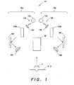
- FIG. 1 is a schematic view of an embodiment of a corneal measurement apparatus 10 according to aspects of the present invention.
- the corneal measurement apparatus is adapted to measure a subject's cornea C.
- the corneal measurement apparatus comprises two slit projection systems 13a, 13b (including light sources 12a and 12b, respectively), two mask subsystems 100a, 100b, and an image capture subsystem 50.
- Mask subsystems 100a and 100b are disposed in the paths of light from slit projection systems 13a and 13b, respectively.
- Slit projection system 13a and mask subsystem 100a are in a first arm 75a of the corneal measurement apparatus and slit projection system 13b and mask subsystem 100b are in a second arm 75b of the corneal measurement apparatus.
- the first arm projects slits of light onto one half of the cornea
- the second arm projects slits of light onto the other half of the cornea.
- the path of each of the projected slits of light may be at a approximately forty-five degree angle to the visual axis of the subject's eye.
- the illustrated embodiment of a measurement apparatus has two arms, in other embodiments, a measurement apparatus may only have a single arm.
- the arm comprises a mask subsystem comprising a first slit mask 130 defining a plurality of apertures 132 i and a slit projection subsystem comprising a light source 12a and a second slit mask 120 defining a selection aperture 122.
- the arm also comprises a movement apparatus 110 adapted to translate the second mask.
- Second slit mask 120 is configured and arranged such that, by appropriately positioning the second slit mask using the movement apparatus to move the second slit mask relative to the first slit mask, selection aperture 122 selectively transmits portions of the light from source 12a such that light traveling through an aperture of the plurality of apertures 132 i impinges on cornea C.
- the movement apparatus may move the selection aperture in any suitable manner to suitably position the selection aperture.
- the movement apparatus may move any suitable portion of the slit projection subsystem to suitably project a slit of light onto a cornea C. For example, as set forth below, the light source may be moved.
- the second slit mask 120 i.e., the mask including the selection aperture
- the first slit mask i.e., the mask including the plurality of apertures
- the second slit mask 120 can be disposed upstream of the second slit mask.
- light sources 12a and 12b generate the light in which a corresponding mask subsystem is disposed.
- the source projects light from the light sources in a cone of light CN to permit light to be projected through each of the apertures defined in first slit mask 130 without moving the source. That is to say that, in some examples, only the second slit mask 120 is moved. The movement occurs to expose a given one of the plurality of apertures on the first mask 130 to light from a light source.
- the plurality of apertures 132 that provide the slits of light can remain fixed in a given location during the acquisition of the plurality of slit images used to produce a representation of a subject's eye.
- the source is monochromatic and suitably bright.
- an LED or a plurality of LEDs may be used to generate the light.
- a high power LED has been found useful.
- a superluminescent LED is used.
- a not claimed aspect of the invention is directed to a single high power LED configured and arranged to be capable of illuminating the plurality of apertures 132 as the selection aperture is moved.
- the condenser lenses 14a, 14b are illustrated as conventional refractive lenses, any suitable imaging element may be used (e.g., a mirror, holographic element). In some examples, the condenser lens may be omitted.
- the projection system components and first slit mask 130 may be disposed in a Scheimpflug arrangement to obtain a plane of slit images at cornea C. Also, one or more folding mirrors 16a and 16b may be included to direct light onto the cornea, and to achieve an appropriate package shape to fit in a housing (not shown) of the apparatus.
- Slit mask 130 includes a plurality of apertures 132 1 - 132 n .
- the slits are of a same width W and length L and are evenly spaced apart; however, aspects of the invention are not so limited.
- Slit mask 120 includes a single selection aperture formed on a substrate 125.
- the selection aperture is sized to permit light to pass from one of the plurality of apertures to cornea C (shown in FIG. 1 ).
- the size of the selection aperture is larger in width and length than any of the plurality of apertures.
- the selection aperture is also typically small enough such that light is only permitted to pass through a single one of the plurality of apertures and onto cornea C.
- the image capture subsystem 50 is arranged to be able to capture an image of light projected for each of the plurality of apertures after the light impinges on the cornea. It will be appreciated that, to capture of the images to obtain a representation of a cornea, each of the plurality of apertures is selected sequentially by appropriately aligning each aperture with the selection aperture as described above.
- Image capture subsystem 50 may be any suitable conventional imaging device, such as a CCD camera.
- Corneal measurement apparatus 10 also includes an image processing subsystem to convert the images into a single representation of the cornea. Techniques for reconstructing a representation of a subject's cornea once the slit images are obtained are well known and are not described further here. Projection systems as described herein may be used with corneal topographers, corneal profiler apparatus and anterior chamber analyzers.
- Corneal measurement apparatus 10 includes a subject positioning apparatus 60 adapted to maintain a subject's cornea in a location.
- the apparatus may be provided with a chin rest and/or a forehead rest which will fix the location of the subject's head.
- FIG. 5 illustrates further details of another example of an embodiment of one arm 200 of corneal measurement apparatus 10 (shown in FIG. 1 ).
- the arm comprises a mask subsystem comprising first slit mask 130 defining a plurality of apertures 132 i ; and a slit projection subsystem 220 comprising a plurality of light sources 212 1-n (shown in FIG. 6 ).
- subsystem 220 is arranged to project a slit of light without the use of a mask having a selection aperture (e.g., mask 120 having a selection aperture 122 in FIG. 2 ).
- the arm also comprises a movement apparatus 210 adapted to move (e.g., translate) the slit projector subsystem 220, so as to appropriately position the plurality of light sources such that light travels through a selected one of the plurality of apertures 132 i and is focused onto cornea C (e.g., by lens 218).
- a movement apparatus 210 adapted to move (e.g., translate) the slit projector subsystem 220, so as to appropriately position the plurality of light sources such that light travels through a selected one of the plurality of apertures 132 i and is focused onto cornea C (e.g., by lens 218).
- FIG. 6 is a schematic illustration of the further details of the light sources 212 1-n included in the illumination slit projection subsystem.
- the sources may, for example, comprise LEDs disposed on a circuit board to project a long narrow band of light. Any suitable number LEDs may be used. Although, a plurality of sources is shown in the illustrated embodiment, a single elongate source may be used.
- FIG. 7 is a schematic view of another example of a corneal measurement apparatus 700 according to aspects of the present invention.
- the corneal measurement apparatus comprises a slit projection systems 713 (including a light source 712), a mask subsystems 731, and an image capture subsystem 750.
- the mask subsystem is disposed in the path of light from slit projection systems 713.
- the mask subsystem comprises a first slit mask 730 defining a plurality of apertures 732 1-n (shown in FIG. 9 ).
Description
- The present invention relates to corneal measurement apparatus and a method of corneal measurement, and more particularly to an apparatus and method for projecting a plurality of slits of light for performing corneal measurements.
- Ophthalmologists and optometrists would like to have an accurate representation of subjects' eye. Such representations include, for example, one or more of a representation of a subject's corneal anterior surface, posterior surface, and corneal thickness and density, as well as anterior chamber profiles. This information may be used to prescribe contact lenses and eye glasses, and to reshape the cornea by surgical procedures or to perform other surgical procedures. Since it is not comfortable to measure these data with physical contact, remote sensing techniques are preferably used to perform the measurements. A device that measures only the front surface of a cornea is commonly referred to as corneal topographer, a device that measures the front and back surfaces of a cornea, and the stroma of the eye is referred to as a corneal profiler, and a device that measures anterior chamber profile including the cornea is called an anterior chamber analyzer.
- One common technique for obtaining corneal measurement information includes projecting narrow bands of light (commonly referred to as slits or slit beams) onto a patient's cornea at multiple locations across a cornea. For each of the slits, after the light in the slit has been scattered by the cornea, an image of the light is obtained.
- To project a slit of light, typically, an aperture of appropriate shape and size, and a lens are placed in the path of light from a light source such that the light passing through the aperture forms a slit of light on a subject's cornea. Typically, to project slits at each of multiple locations across the cornea, a single aperture is translated such that the light passing through the aperture at selected times forms the multiple slits. One example of such a corneal measurement apparatus is presented in
U.S. Patent 5,512,966 to Snook. A further example of a corneal measurement apparatus is disclosed in U.S. Patent Application PublicationUS 2005/0 134 797 A1 . - A problem with such devices is that it is difficult to accurately position an aperture to form each of the slits, and over time (after many patients) it is difficult to know the position of the slits accurately so that an accurate recreation of a cornea can be obtained.
- Aspects of the present invention are directed to eye measurement apparatus having a slit mask defining a plurality of apertures for projecting slits of light onto an eye.
- An aspect of the present invention is directed to an apparatus according to claim 1.
- In some embodiments, the slit projection subsystem comprises a second slit mask defining a selection aperture, the movement apparatus being adapted to move the second slit mask.
- In some examples, the apparatus further comprises (F.) a second slit projection subsystem comprising a second light source, (G.) a second mask subsystem disposed in a path of second light from the second slit projection subsystem, comprising a second slit mask defining a second plurality of apertures, (H.) a second movement apparatus adapted to move at least a portion of the second slit projection subsystem, the second movement apparatus configured and arranged such that by moving the portion of the second slit projection subsystem, portions of the second light can be selectively transmitted through an aperture of the second plurality of apertures toward the cornea; and (I.) a second imaging element configured and arranged to image the second plurality of apertures onto the cornea, the image capture subsystem arranged to capture images of the portions of second light after the light impinges on the cornea.
- In some embodiments, the second slit mask is disposed upstream of the first slit mask. In some examples, the slit projection subsystem is configured and arranged to project light from the light source through each of the plurality of apertures defined in first slit mask without moving the light source.
- In some examples, the light source comprises at least one LED arranged to project light in the path of light. In some examples, the apparatus further comprises a condenser lens configured and arranged to gather light from the light source and project the light in the path of light. In some examples, the imaging element and condenser lens are configured and arranged to operate as a condenser-projector system. In some examples, the imaging element and the first slit mask are disposed in a Scheimpflug arrangement to obtain a plane of slit images at the cornea.
- In some embodiments, the plurality of apertures is disposed in a single plane. In some embodiments, the plurality of apertures is formed on a single substrate. In some examples, the plurality of apertures is defined by openings in an opaque layer deposited on the substrate.
- In some embodiments, the apparatus comprises an image processing subsystem coupled to the image capture subsystem, the image processing subsystem being adapted to convert the images into a representation of the cornea. In some examples, the apparatus further comprises a subject positioning apparatus adapted to maintain the subject's cornea in a location.
- In some examples, the light source comprises at least one high power LED. In some examples, the light source consists of a single LED.
- In some embodiments, the movement apparatus is adapted to translate the at least portion of the slit projection subsystem. In some embodiments, the light source is adapted to project a slit of light and the movement apparatus is adapted to translate the light source. In some embodiments, the movement apparatus is adapted to translate the second slit mask. In some embodiments, the movement apparatus is adapted to rotate the at least portion of the slit projection subsystem.
- Another aspect of the present invention is directed to a method of facilitating measurement of a subject's cornea, comprising: (A.) providing a plurality of apertures, (B.) projecting light toward the plurality of apertures, (C.) moving at least a portion of a slit projector subsystem while maintaining the plurality of apertures in fixed locations to selectively transmit a portion of the light toward the cornea, the portion of the light passing through a selected aperture of the plurality of apertures; and, (D.) imaging the portions of light after the light impinges on the cornea.
- In some embodiments, the step of moving comprises translating the at least portion of the slit projection subsystem. In some embodiments, the step of moving comprises rotating the at least portion of the slit projection subsystem.
- In some embodiments, the step of moving comprises moving a selection slit. In some examples, the step of moving comprises moving at least one source.
- In some examples, the light passes through the selection aperture prior to passing through any of the plurality of apertures. In some examples, the step of projecting light comprises projecting light from at least one LED. In some embodiments, the step of imaging produces images, and the method further comprises processing the images to convert the images into a representation of the cornea.
- Illustrative, non-limiting embodiments of the present invention will be described by way of example with reference to the accompanying drawings, in which the same reference number is used to designate the same or similar components in different figures, and in which:
-
FIG. 1 is a schematic view of an example of a corneal measurement apparatus according to aspects of the present invention; -
FIG. 2 is an expanded view showing further details of one arm of the corneal measurement apparatus ofFIG. 1 ; -
FIG. 3 is an illustration of an example of an embodiment of a first slit mask defining a plurality of apertures viewed along line 3 - 3 ofFIG. 2 ; -
FIG. 4 is an illustration of an example of an embodiment of a second slit mask defining a selection aperture viewed along line 4 - 4 ofFIG. 2 ; -
FIG. 5 illustrates further details of another example of an embodiment of one arm of the corneal measurement apparatus shown inFIG. 1 ; -
FIG. 6 is a schematic illustration of further details of one example of light sources included in a slit projection subsystem; -
FIG. 7 is a schematic view of another example of a corneal measurement apparatus according to aspects of the present invention; -
FIG. 8 is an illustration of an example of an embodiment of a second slit mask defining a selection aperture viewed along line 8 - 8 ofFIG. 7 ; and -
FIG. 9 is an illustration of further details of an example of an embodiment of first slit mask defining a plurality of apertures viewed along line 9 - 9 ofFIG. 7 . -
FIG. 1 is a schematic view of an embodiment of acorneal measurement apparatus 10 according to aspects of the present invention. The corneal measurement apparatus is adapted to measure a subject's cornea C. The corneal measurement apparatus comprises twoslit projection systems light sources mask subsystems image capture subsystem 50.Mask subsystems slit projection systems -
Slit projection system 13a andmask subsystem 100a are in afirst arm 75a of the corneal measurement apparatus andslit projection system 13b andmask subsystem 100b are in asecond arm 75b of the corneal measurement apparatus. In the illustrated embodiment, the first arm projects slits of light onto one half of the cornea, and the second arm projects slits of light onto the other half of the cornea. For example, the path of each of the projected slits of light may be at a approximately forty-five degree angle to the visual axis of the subject's eye. Although the illustrated embodiment of a measurement apparatus has two arms, in other embodiments, a measurement apparatus may only have a single arm. - Referring to
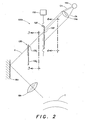
FIG. 2 , further details of an example embodiment of one arm of thecorneal measurement apparatus 10 are shown. The arm comprises a mask subsystem comprising afirst slit mask 130 defining a plurality ofapertures 132i and a slit projection subsystem comprising alight source 12a and asecond slit mask 120 defining aselection aperture 122. - The arm also comprises a
movement apparatus 110 adapted to translate the second mask.Second slit mask 120 is configured and arranged such that, by appropriately positioning the second slit mask using the movement apparatus to move the second slit mask relative to the first slit mask,selection aperture 122 selectively transmits portions of the light fromsource 12a such that light traveling through an aperture of the plurality ofapertures 132i impinges on cornea C. It will be appreciated that although in the illustrated embodiment, the movement apparatus translates the second mask, the movement apparatus may move the selection aperture in any suitable manner to suitably position the selection aperture. Also, the movement apparatus may move any suitable portion of the slit projection subsystem to suitably project a slit of light onto a cornea C. For example, as set forth below, the light source may be moved. - Ray R demonstrates that the
selection aperture 122 transmits light to cornea C from a selected one 1321 of the plurality of apertures, whenselection aperture 122 is appropriately aligned with the selected one 1321 of the plurality of apertures. Subsequently, by translatingsecond slit mask 120, the selection aperture can be positioned such that light from another of the plurality ofapertures 132n can be transmitted to cornea C. Such positioning of the selection aperture can be repeated such that light from each of the plurality of apertures or light from any suitable ones of the plurality ofapertures 132 can be transmitted to cornea C. It will be appreciated that, on portions of the first slit mask and the second slit mask that are outside of the apertures disposed thereon, the slit masks are opaque or substantially opaque to light fromsource 12a. - It is to be appreciated that although, in the illustrated embodiment, the second slit mask 120 (i.e., the mask including the selection aperture) is disposed upstream (i.e., closer to source 12a along the optical path) from
first slit mask 130, in other embodiments, the first slit mask (i.e., the mask including the plurality of apertures) can be disposed upstream of the second slit mask. - Referring again to
FIG. 1 ,light sources first slit mask 130 without moving the source. That is to say that, in some examples, only thesecond slit mask 120 is moved. The movement occurs to expose a given one of the plurality of apertures on thefirst mask 130 to light from a light source. It will be appreciated that, in such examples, the plurality ofapertures 132 that provide the slits of light can remain fixed in a given location during the acquisition of the plurality of slit images used to produce a representation of a subject's eye. An advantage over prior art measurement apparatus, in which a single aperture is moved to produce slits of light, is that slits of light are produced with positions that are more accurately known, thereby providing more accurate representations of subjects' eyes. - In some examples, it is advantageous if the source is monochromatic and suitably bright. For example, an LED or a plurality of LEDs may be used to generate the light. In some examples, a high power LED has been found useful. In some examples, a superluminescent LED is used. A not claimed aspect of the invention is directed to a single high power LED configured and arranged to be capable of illuminating the plurality of
apertures 132 as the selection aperture is moved. - In some examples, it is advantageous that the projection subsystem include a conventional condenser-projector system. In
FIG. 1 ,condenser lenses sources projector lenses lenses images sources projector lenses apertures 132 onto cornea C. It is typically preferable that the slits of light are not convergent or divergent between the first slit mask and the cornea. However, some convergence or divergence may be present. Although in the illustrated embodiment theprojector lenses - Although in the illustrated embodiment the
condenser lenses first slit mask 130 may be disposed in a Scheimpflug arrangement to obtain a plane of slit images at cornea C. Also, one or more folding mirrors 16a and 16b may be included to direct light onto the cornea, and to achieve an appropriate package shape to fit in a housing (not shown) of the apparatus. - Further details of
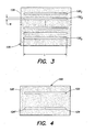
first slit mask 130 are now given with reference toFIG. 3 .Slit mask 130 includes a plurality of apertures 1321 - 132n. Typically, the slits are of a same width W and length L and are evenly spaced apart; however, aspects of the invention are not so limited. - For example, twenty apertures may be provided on the slit mask in
first arm 75a (shown inFIG. 1 ) so that twenty slits of light are projected onto a subject's cornea and twenty images are obtained using light from thefirst arm 75a of the measurement apparatus 10 (shown inFIG. 1 ). Accordingly, when combined with twenty images fromsecond arm 75b (shown inFIG. 1 ) a total of 40 slit images of a subject's eye are obtained. It will be appreciated that any suitable number of apertures may be provided on the first slit mask in each ofmask subsystems FIG. 1 ). - For example,
first slit mask 130 may be formed on asubstrate 135 of soda lime glass or BK7 glass. An opaque layer may be deposited on a surface of the substrate. For example, an opaque metal layer may be deposited on the substrate, and the apertures may be subsequently formed by etching a portion of the metal layer to expose the substrate. Each of the apertures is sized and shaped such that in a given measurement apparatus a slit of light is projected onto a cornea in a conventional manner. Typically, the apertures are rectangular in shape. However, any suitable shape may be employed. In some examples, it may be desirable to apply an antireflective coating to one or both of the surfaces of a substrate. Although the plurality ofapertures 132 are shown as being formed on a single substrate (and in a single plane) any suitable construction may be used in which the apertures are formed at fixed locations relative to one another. - Further details of the
second slit mask 120 are now given with reference toFIG. 4 .Slit mask 120 includes a single selection aperture formed on asubstrate 125. The selection aperture is sized to permit light to pass from one of the plurality of apertures to cornea C (shown inFIG. 1 ). Typically, the size of the selection aperture is larger in width and length than any of the plurality of apertures. The selection aperture is also typically small enough such that light is only permitted to pass through a single one of the plurality of apertures and onto cornea C. - In the illustrated embodiment of the second slit mask, an aperture portion 124 (typically half the length of the selection aperture) is also provided. The aperture portion is used for alignment of the measurement apparatus relative to a subject's cornea on whom a corneal measurement is to be made. The aperture portion is aligned with one of the plurality of apertures on the first slit mask, such that light is projected though only a portion of the one of the plurality of apertures and a portion of a slit of light is projected onto the middle of a subject's eye by the
first arm 75a (shown inFIG. 1 ) (e.g., an upper half of a slit is formed at the middle of the subject's eye by the first arm). - Another,
second slit mask 120 also having an aperture portion is disposed in theother arm 75b (shown inFIG. 1 ). The position of aperture portion 124' in a second slit mask (in thesecond arm 75b) is shown in dashed lines. Similar, to the aperture portion in the first arm, the aperture portion in the second arm is aligned with one of the plurality of apertures on the first slit mask of the second arm. Again, the aperture is arranged to project light onto the middle of the subject's cornea (e.g., a lower half of an aperture is formed at the middle of the subject's eye). In a conventional manner, the subject's cornea is aligned with the measurement apparatus, by positioning either the subject or the machine such that the two portions of the slits of light align to form a single, full-length slit of light (e.g., the upper half of the slit of light from the first arm aligns with the lower half of the slit of light from the second arm) to form a single, full slit of light. The second slit masks 120 (in the first and second arm) may be formed in a manner similar to that described above for thefirst slit mask 130. - Referring again to
FIG. 1 , theimage capture subsystem 50 is arranged to be able to capture an image of light projected for each of the plurality of apertures after the light impinges on the cornea. It will be appreciated that, to capture of the images to obtain a representation of a cornea, each of the plurality of apertures is selected sequentially by appropriately aligning each aperture with the selection aperture as described above.Image capture subsystem 50 may be any suitable conventional imaging device, such as a CCD camera. -
Movement apparatus 110 may comprise any suitable mechanism for moving (e.g., translating) thesecond mask 120 to project slits of light form the plurality ofapertures 132 on thefirst slit mask 130 to cornea C. For example, the movement apparatus may comprise a linear translation motor capable of the moving (i.e., translating) the second slit mask in a direction perpendicular to the length L of the plurality ofapertures 132. -
Corneal measurement apparatus 10 also includes an image processing subsystem to convert the images into a single representation of the cornea. Techniques for reconstructing a representation of a subject's cornea once the slit images are obtained are well known and are not described further here. Projection systems as described herein may be used with corneal topographers, corneal profiler apparatus and anterior chamber analyzers. -
Corneal measurement apparatus 10 includes a subject positioning apparatus 60 adapted to maintain a subject's cornea in a location. For example, the apparatus may be provided with a chin rest and/or a forehead rest which will fix the location of the subject's head. -
FIG. 5 illustrates further details of another example of an embodiment of onearm 200 of corneal measurement apparatus 10 (shown inFIG. 1 ). The arm comprises a mask subsystem comprisingfirst slit mask 130 defining a plurality ofapertures 132i; and aslit projection subsystem 220 comprising a plurality of light sources 2121-n (shown inFIG. 6 ). It will be appreciated that, in contrast to the embodiment shown inFIG. 2 ,subsystem 220 is arranged to project a slit of light without the use of a mask having a selection aperture (e.g.,mask 120 having aselection aperture 122 inFIG. 2 ). In some examples, the projection subsystem comprises acylindrical lens 222 to gather light from the light sources and focus it on a selected one of theapertures 132i. Alternative arrangements for projecting a slit of light are given inU.S. Pat. 6,409,346 (issued June 25, 2002 ) and6,286,958 (issued September 11, 2001 ) both to Koest. Additionally, aprism 223 may be located in the path of the slit of light to improve homogeneity of the light, the prism being rotated or oscillated as taught inU.S. Patent 7,040,765 (issued May 9, 2006 ). The substance of said three (3) patents is hereby incorporated by reference. - The arm also comprises a
movement apparatus 210 adapted to move (e.g., translate) theslit projector subsystem 220, so as to appropriately position the plurality of light sources such that light travels through a selected one of the plurality ofapertures 132i and is focused onto cornea C (e.g., by lens 218). -
FIG. 6 is a schematic illustration of the further details of thelight sources 2121-n included in the illumination slit projection subsystem. The sources may, for example, comprise LEDs disposed on a circuit board to project a long narrow band of light. Any suitable number LEDs may be used. Although, a plurality of sources is shown in the illustrated embodiment, a single elongate source may be used. -
FIG. 7 is a schematic view of another example of acorneal measurement apparatus 700 according to aspects of the present invention. The corneal measurement apparatus comprises a slit projection systems 713 (including a light source 712), amask subsystems 731, and animage capture subsystem 750. The mask subsystem is disposed in the path of light fromslit projection systems 713. The mask subsystem comprises afirst slit mask 730 defining a plurality of apertures 7321-n (shown inFIG. 9 ). -
Slit projection systems 713 comprises a light source 712, asecond slit mask 720 defining a selection aperture 722 (shown inFIG. 8 ), and a slit imaging lens 740 (e.g., a cylindrical lens having a length aligned with the length of the selection aperture).Slit projection systems 713 also comprises amovement apparatus 710 adapted to rotate source 712 andsecond mask 720. By appropriately positioning the second slit mask using the movement apparatus,selection aperture 722 selectively transmits portions of the light from source 712 such that light traveling through a selected one of the plurality ofapertures 732i impinges on cornea C. As discussed above, in some embodiments, the source may project a cone of light such that movement of the source is not necessary to project a plurality of slits of light. - In some embodiments,
imaging lens 740 is rotated by movement apparatus along with source 712 andsecond mask 720; alternatively, a plurality of imaging lenses can be arranged such that one is aligned with each of the plurality of apertures offirst slit mask 730. It will be appreciated that, in embodiments as illustrated inFIG. 7 , the plurality ofapertures 732 that provide the slits of light can remain fixed in a given location during the acquisition of the plurality of slit images used to produce a representation of a subject's eye. An advantage over prior art measurement apparatus is that slits of light are produced with positions that are more accurately known than with conventional apparatus, thereby providing more accurate representations of subjects' eyes. -
FIG. 8 is an illustration of an example of an embodiment of asecond slit mask 720 defining aselection aperture 722 viewed along line 8 - 8 ofFIG. 7 .FIG. 9 is an illustration of further details of an example of an embodiment offirst slit mask 730 defining a plurality ofapertures 732i viewed along line 9 - 9 ofFIG. 7 . It will be appreciated that, in some embodiments, slitprojection system 713 comprises a source as inFIG. 2 ; and in other embodiments, slitprojection system 713 is constructed as slit projection system 220 (shown inFIG. 6 ) and as such comprises a source or sources configured to project a slit of light without the use of a selection aperture. - Having thus described the inventive concepts and a number of exemplary embodiments, it will be apparent to those skilled in the art that the invention may be implemented in various ways, and that modifications and improvements will readily occur to such persons. Thus, the embodiments are not intended to be limiting and presented by way of example only. The invention is limited only as required by the following claims and equivalents thereto.
Claims (15)
- An apparatus for measuring a subject's cornea, comprising:(A.) a slit projection subsystem comprising a light source (12a);(B.) a mask subsystem (100a) disposed in a path of light from the light source (12a), comprising a first slit mask (130) defining a plurality of apertures (132i), the plurality of apertures (132i) adapted to remain fixed in a location during measurement of the subject's cornea;(C.) a movement apparatus (110) adapted to move at least a portion of the slit projection subsystem, the movement apparatus (110) configured and arranged such that, by moving the portion of the slit projection subsystem, portions of the light can be selectively transmitted through an aperture of the plurality of apertures (132i) toward the cornea;(D.) an imaging element (14a, 14b, 18a, 18b) configured and arranged to image at least one of the plurality of apertures (132i) onto the cornea; and(E.) an image capture subsystem (50) arranged to capture images of the portions of light after the light impinges on the cornea.
- The apparatus of claim 1, wherein the slit projection subsystem comprises a second slit mask (120) defining selection aperture (122), the movement apparatus (110) being adapted to move the second slit mask (120).
- The apparatus in claim 2, wherein the second slit mask (120) is disposed upstream of the first slit mask (120).
- The apparatus in claim 1, wherein the plurality of apertures (132i) are disposed in a single plane.
- The apparatus in claim 1, wherein the plurality of apertures (132i) are formed on a single substrate.
- The apparatus in claim 1, further comprising an image processing subsystem coupled to the image capture subsystem (50), the image processing subsystem being adapted to convert the images into a representation of the cornea.
- The apparatus of claim 1, wherein the movement apparatus (110) is adapted to translate the at least portion of the slit projection subsystem.
- The apparatus of claim 7, wherein the light source (12a) is adapted to project a slit of light and the movement avparatus (110) is adapted to translate the light source (12a).
- The apparatus of claim 2, wherein the movement apparatus (110) is adapted to translate the second slit mask (120).
- The apparatus of claim 1, wherein the movement apparatus (110) is adapted to rotate the at least portion of the slit projection subsystem.
- A method of facilitating measurement of a subject's cornea, comprising:(A.) providing a plurality of apertures (132i);(B.) projecting light toward the plurality of apertures (132i);(C.) moving at least a portion of a slit projector subsystem while maintaining the plurality of apertures (132i) in a fixed locations to selectively transit a portion of the light toward the cornea, the portion of the light passing through a selected aperture of the plurality of aperturs (132i); and(D.) imaging the portions of light after the light impinges on the cornea.
- The method of claim 11, where the step of moving comprises translating the at least portion of the slit projection subsystem.
- The method of claim 11, where the step of moving comprises rotating the at least portion of the slit projection subsystem.
- The method of claim 11, where the moving comprises moving a selection slit (122).
- The method of claim 11, wherein the step of imaging produces images, and the method further comprises processing the images to convert the images into a representation of the cornea.
Priority Applications (1)
| Application Number | Priority Date | Filing Date | Title |
|---|---|---|---|
| PL07855209T PL2101631T3 (en) | 2006-12-21 | 2007-12-17 | Corneal measurement apparatus and a method of using the same |
Applications Claiming Priority (2)
| Application Number | Priority Date | Filing Date | Title |
|---|---|---|---|
| US11/614,518 US20080151190A1 (en) | 2006-12-21 | 2006-12-21 | Corneal measurment apparatus and a method of using the same |
| PCT/US2007/087747 WO2008079766A1 (en) | 2006-12-21 | 2007-12-17 | Corneal measurement apparatus and a method of using the same |
Publications (2)
| Publication Number | Publication Date |
|---|---|
| EP2101631A1 EP2101631A1 (en) | 2009-09-23 |
| EP2101631B1 true EP2101631B1 (en) | 2015-09-02 |
Family
ID=39415139
Family Applications (1)
| Application Number | Title | Priority Date | Filing Date |
|---|---|---|---|
| EP07855209.8A Active EP2101631B1 (en) | 2006-12-21 | 2007-12-17 | Corneal measurement apparatus and a method of using the same |
Country Status (5)
| Country | Link |
|---|---|
| US (2) | US20080151190A1 (en) |
| EP (1) | EP2101631B1 (en) |
| ES (1) | ES2547278T3 (en) |
| PL (1) | PL2101631T3 (en) |
| WO (1) | WO2008079766A1 (en) |
Families Citing this family (18)
| Publication number | Priority date | Publication date | Assignee | Title |
|---|---|---|---|---|
| EP1173790A2 (en) | 1999-03-01 | 2002-01-23 | Boston Innovative Optics, Inc. | System and method for increasing the depth of focus of the human eye |
| US7628810B2 (en) | 2003-05-28 | 2009-12-08 | Acufocus, Inc. | Mask configured to maintain nutrient transport without producing visible diffraction patterns |
| US20050046794A1 (en) | 2003-06-17 | 2005-03-03 | Silvestrini Thomas A. | Method and apparatus for aligning a mask with the visual axis of an eye |
| EP2947418A1 (en) * | 2008-01-08 | 2015-11-25 | AMO WaveFront Sciences, LLC | Systems and methods for measuring surface shape |
| JP5355994B2 (en) * | 2008-11-05 | 2013-11-27 | 株式会社ニデック | Ophthalmic imaging equipment |
| US10004593B2 (en) | 2009-08-13 | 2018-06-26 | Acufocus, Inc. | Intraocular lens with elastic mask |
| IN2012DN02153A (en) | 2009-08-13 | 2015-08-07 | Acufocus Inc | |
| IN2012DN02154A (en) | 2009-08-13 | 2015-08-07 | Acufocus Inc | |
| US20120203239A1 (en) * | 2009-10-13 | 2012-08-09 | Acufocus,Inc. | Method and apparatus for centration of an ocular implant |
| US20140098342A1 (en) * | 2011-11-04 | 2014-04-10 | The General Hospital Corporation | System and method for corneal irradiation |
| WO2013082545A1 (en) | 2011-12-02 | 2013-06-06 | Acufocus, Inc. | Ocular mask having selective spectral transmission |
| US9204962B2 (en) | 2013-03-13 | 2015-12-08 | Acufocus, Inc. | In situ adjustable optical mask |
| US9427922B2 (en) | 2013-03-14 | 2016-08-30 | Acufocus, Inc. | Process for manufacturing an intraocular lens with an embedded mask |
| EP3220859B8 (en) | 2014-11-19 | 2020-06-10 | AcuFocus, Inc. | Fracturable mask for treating presbyopia |
| EP3359987B1 (en) | 2015-10-05 | 2024-02-28 | AcuFocus, Inc. | Methods of molding intraocular lenses |
| CA3005891C (en) | 2015-11-24 | 2023-12-12 | Acufocus, Inc. | Toric small aperture intraocular lens with extended depth of focus |
| EP3443883B1 (en) * | 2017-08-14 | 2020-07-29 | Carl Zeiss Vision International GmbH | Method and devices for performing eye-related measurements |
| WO2019217471A1 (en) | 2018-05-09 | 2019-11-14 | Acufocus, Inc. | Intraocular implant with removable optic |
Family Cites Families (17)
| Publication number | Priority date | Publication date | Assignee | Title |
|---|---|---|---|---|
| JPS55125844A (en) * | 1979-03-20 | 1980-09-29 | Canon Kk | Optic refractometer |
| JPS56132936A (en) * | 1980-03-21 | 1981-10-17 | Tokyo Optical | Eye bottom camera |
| AU716040B2 (en) * | 1993-06-24 | 2000-02-17 | Bausch & Lomb Incorporated | Ophthalmic pachymeter and method of making ophthalmic determinations |
| DE29913603U1 (en) * | 1999-08-04 | 1999-11-25 | Oculus Optikgeraete Gmbh | Slit projector |
| DE29913602U1 (en) * | 1999-08-04 | 1999-11-25 | Oculus Optikgeraete Gmbh | Device for eye examination with a Scheimpflug camera and a slit projector for taking sectional images of an eye |
| AU2001260197A1 (en) * | 2000-04-11 | 2001-10-23 | Thomas Bende | Selective corneal aberrometry |
| JP3709335B2 (en) * | 2000-09-28 | 2005-10-26 | 株式会社ニデック | Ophthalmic equipment |
| JP2003047595A (en) * | 2001-08-06 | 2003-02-18 | Nidek Co Ltd | Ophthalmic imaging system |
| US6575573B2 (en) * | 2001-10-17 | 2003-06-10 | Carl Zeiss Ophthalmic Systems, Inc. | Method and apparatus for measuring a corneal profile of an eye |
| JP3978024B2 (en) * | 2001-12-03 | 2007-09-19 | 株式会社ニデック | Ophthalmic device and corneal surgery device |
| DE20306542U1 (en) * | 2003-04-25 | 2003-08-28 | Oculus Optikgeraete Gmbh | Device for projecting a light beam |
| WO2005000113A1 (en) * | 2003-06-30 | 2005-01-06 | Right Mfg, Co., Ltd. | Ocular refractive power measuring instrument |
| US7070276B2 (en) * | 2003-12-04 | 2006-07-04 | Rensselaer Polytechnic Institute | Apparatus and method for accommodative stimulation of an eye and simultaneous ipsilateral accommodative imaging |
| US7347549B2 (en) * | 2003-12-10 | 2008-03-25 | Bausch & Lomb Incorporated | Rapid switching slit scan image capture system |
| JP2005237901A (en) * | 2004-03-01 | 2005-09-08 | Nidek Co Ltd | Ophthalmological device |
| EP1738680B1 (en) * | 2005-07-01 | 2011-03-09 | Nidek Co., Ltd. | Ophthalmic apparatus |
| JP4987408B2 (en) * | 2006-09-29 | 2012-07-25 | 株式会社ニデック | Ophthalmic equipment |
-
2006
- 2006-12-21 US US11/614,518 patent/US20080151190A1/en not_active Abandoned
-
2007
- 2007-12-12 US US11/955,001 patent/US7648241B2/en active Active
- 2007-12-17 PL PL07855209T patent/PL2101631T3/en unknown
- 2007-12-17 EP EP07855209.8A patent/EP2101631B1/en active Active
- 2007-12-17 WO PCT/US2007/087747 patent/WO2008079766A1/en active Application Filing
- 2007-12-17 ES ES07855209.8T patent/ES2547278T3/en active Active
Also Published As
| Publication number | Publication date |
|---|---|
| ES2547278T3 (en) | 2015-10-02 |
| US7648241B2 (en) | 2010-01-19 |
| US20080151190A1 (en) | 2008-06-26 |
| US20080212030A1 (en) | 2008-09-04 |
| WO2008079766A1 (en) | 2008-07-03 |
| PL2101631T3 (en) | 2016-03-31 |
| EP2101631A1 (en) | 2009-09-23 |
Similar Documents
| Publication | Publication Date | Title |
|---|---|---|
| EP2101631B1 (en) | Corneal measurement apparatus and a method of using the same | |
| JP4553578B2 (en) | Ophthalmic apparatus and ophthalmic measurement method | |
| JP5756253B2 (en) | Surgical microscope system with optical coherence tomography mechanism | |
| US20090096987A1 (en) | Eye Measurement Apparatus and a Method of Using Same | |
| KR100992182B1 (en) | Ophthalmic binocular wavefront measurement system | |
| JPS6216088B2 (en) | ||
| EA004236B1 (en) | System and method for the non-contacting measurement of the axis length, and/or cornea curvature, and/or anterior chamber depth of the eye, preferably for intraocular lens calculation | |
| JP7167417B2 (en) | Fundus imaging device and ophthalmic device | |
| JP3916482B2 (en) | Ophthalmic equipment | |
| US6382794B1 (en) | Method and apparatus for mapping a corneal contour and thickness profile | |
| US7896497B2 (en) | Corneal measurement apparatus having a segmented aperture and a method of using the same | |
| JP4722853B2 (en) | Device for the measurement of the front of the eye | |
| EP0337651A1 (en) | Ophthalmological diagnosis method and apparatus | |
| US3572908A (en) | Apparatus for measuring and recording refractive errors of a patient{3 s eye | |
| JP6095439B2 (en) | Ophthalmic apparatus, control method thereof, and program | |
| JPS6125371B2 (en) | ||
| US11089956B2 (en) | Ophthalmologic apparatus and method of controlling the same | |
| US11154190B2 (en) | Eye surface topographer | |
| JP3594447B2 (en) | Ophthalmic equipment | |
| JPH09108185A (en) | Ophthalmological device | |
| JP7279349B2 (en) | ophthalmic equipment | |
| US3776620A (en) | Opthalmometer having alternative viewing and measuring systems | |
| JP2022105110A (en) | Ophthalmologic apparatus | |
| JPH0554325B2 (en) | ||
| JPS61206422A (en) | Visual field measuring apparatus |
Legal Events
| Date | Code | Title | Description |
|---|---|---|---|
| PUAI | Public reference made under article 153(3) epc to a published international application that has entered the european phase |
Free format text: ORIGINAL CODE: 0009012 |
|
| 17P | Request for examination filed |
Effective date: 20090716 |
|
| AK | Designated contracting states |
Kind code of ref document: A1 Designated state(s): AT BE BG CH CY CZ DE DK EE ES FI FR GB GR HU IE IS IT LI LT LU LV MC MT NL PL PT RO SE SI SK TR |
|
| DAX | Request for extension of the european patent (deleted) | ||
| 17Q | First examination report despatched |
Effective date: 20111219 |
|
| GRAP | Despatch of communication of intention to grant a patent |
Free format text: ORIGINAL CODE: EPIDOSNIGR1 |
|
| INTG | Intention to grant announced |
Effective date: 20150312 |
|
| GRAS | Grant fee paid |
Free format text: ORIGINAL CODE: EPIDOSNIGR3 |
|
| GRAA | (expected) grant |
Free format text: ORIGINAL CODE: 0009210 |
|
| AK | Designated contracting states |
Kind code of ref document: B1 Designated state(s): AT BE BG CH CY CZ DE DK EE ES FI FR GB GR HU IE IS IT LI LT LU LV MC MT NL PL PT RO SE SI SK TR |
|
| REG | Reference to a national code |
Ref country code: GB Ref legal event code: FG4D |
|
| REG | Reference to a national code |
Ref country code: AT Ref legal event code: REF Ref document number: 746017 Country of ref document: AT Kind code of ref document: T Effective date: 20150915 Ref country code: CH Ref legal event code: EP |
|
| REG | Reference to a national code |
Ref country code: IE Ref legal event code: FG4D |
|
| REG | Reference to a national code |
Ref country code: FR Ref legal event code: PLFP Year of fee payment: 9 |
|
| REG | Reference to a national code |
Ref country code: ES Ref legal event code: FG2A Ref document number: 2547278 Country of ref document: ES Kind code of ref document: T3 Effective date: 20151002 |
|
| REG | Reference to a national code |
Ref country code: DE Ref legal event code: R096 Ref document number: 602007042941 Country of ref document: DE |
|
| REG | Reference to a national code |
Ref country code: AT Ref legal event code: MK05 Ref document number: 746017 Country of ref document: AT Kind code of ref document: T Effective date: 20150902 |
|
| PG25 | Lapsed in a contracting state [announced via postgrant information from national office to epo] |
Ref country code: GR Free format text: LAPSE BECAUSE OF FAILURE TO SUBMIT A TRANSLATION OF THE DESCRIPTION OR TO PAY THE FEE WITHIN THE PRESCRIBED TIME-LIMIT Effective date: 20151203 Ref country code: LT Free format text: LAPSE BECAUSE OF FAILURE TO SUBMIT A TRANSLATION OF THE DESCRIPTION OR TO PAY THE FEE WITHIN THE PRESCRIBED TIME-LIMIT Effective date: 20150902 Ref country code: LV Free format text: LAPSE BECAUSE OF FAILURE TO SUBMIT A TRANSLATION OF THE DESCRIPTION OR TO PAY THE FEE WITHIN THE PRESCRIBED TIME-LIMIT Effective date: 20150902 Ref country code: FI Free format text: LAPSE BECAUSE OF FAILURE TO SUBMIT A TRANSLATION OF THE DESCRIPTION OR TO PAY THE FEE WITHIN THE PRESCRIBED TIME-LIMIT Effective date: 20150902 |
|
| REG | Reference to a national code |
Ref country code: LT Ref legal event code: MG4D Ref country code: NL Ref legal event code: MP Effective date: 20150902 |
|
| PG25 | Lapsed in a contracting state [announced via postgrant information from national office to epo] |
Ref country code: SE Free format text: LAPSE BECAUSE OF FAILURE TO SUBMIT A TRANSLATION OF THE DESCRIPTION OR TO PAY THE FEE WITHIN THE PRESCRIBED TIME-LIMIT Effective date: 20150902 Ref country code: AT Free format text: LAPSE BECAUSE OF FAILURE TO SUBMIT A TRANSLATION OF THE DESCRIPTION OR TO PAY THE FEE WITHIN THE PRESCRIBED TIME-LIMIT Effective date: 20150902 |
|
| PG25 | Lapsed in a contracting state [announced via postgrant information from national office to epo] |
Ref country code: SK Free format text: LAPSE BECAUSE OF FAILURE TO SUBMIT A TRANSLATION OF THE DESCRIPTION OR TO PAY THE FEE WITHIN THE PRESCRIBED TIME-LIMIT Effective date: 20150902 Ref country code: NL Free format text: LAPSE BECAUSE OF FAILURE TO SUBMIT A TRANSLATION OF THE DESCRIPTION OR TO PAY THE FEE WITHIN THE PRESCRIBED TIME-LIMIT Effective date: 20150902 Ref country code: IS Free format text: LAPSE BECAUSE OF FAILURE TO SUBMIT A TRANSLATION OF THE DESCRIPTION OR TO PAY THE FEE WITHIN THE PRESCRIBED TIME-LIMIT Effective date: 20160102 Ref country code: CZ Free format text: LAPSE BECAUSE OF FAILURE TO SUBMIT A TRANSLATION OF THE DESCRIPTION OR TO PAY THE FEE WITHIN THE PRESCRIBED TIME-LIMIT Effective date: 20150902 Ref country code: EE Free format text: LAPSE BECAUSE OF FAILURE TO SUBMIT A TRANSLATION OF THE DESCRIPTION OR TO PAY THE FEE WITHIN THE PRESCRIBED TIME-LIMIT Effective date: 20150902 |
|
| PG25 | Lapsed in a contracting state [announced via postgrant information from national office to epo] |
Ref country code: BE Free format text: LAPSE BECAUSE OF NON-PAYMENT OF DUE FEES Effective date: 20151231 Ref country code: PT Free format text: LAPSE BECAUSE OF FAILURE TO SUBMIT A TRANSLATION OF THE DESCRIPTION OR TO PAY THE FEE WITHIN THE PRESCRIBED TIME-LIMIT Effective date: 20160104 Ref country code: RO Free format text: LAPSE BECAUSE OF FAILURE TO SUBMIT A TRANSLATION OF THE DESCRIPTION OR TO PAY THE FEE WITHIN THE PRESCRIBED TIME-LIMIT Effective date: 20150902 |
|
| REG | Reference to a national code |
Ref country code: DE Ref legal event code: R097 Ref document number: 602007042941 Country of ref document: DE |
|
| PLBE | No opposition filed within time limit |
Free format text: ORIGINAL CODE: 0009261 |
|
| STAA | Information on the status of an ep patent application or granted ep patent |
Free format text: STATUS: NO OPPOSITION FILED WITHIN TIME LIMIT |
|
| PG25 | Lapsed in a contracting state [announced via postgrant information from national office to epo] |
Ref country code: LU Free format text: LAPSE BECAUSE OF FAILURE TO SUBMIT A TRANSLATION OF THE DESCRIPTION OR TO PAY THE FEE WITHIN THE PRESCRIBED TIME-LIMIT Effective date: 20151217 Ref country code: MC Free format text: LAPSE BECAUSE OF FAILURE TO SUBMIT A TRANSLATION OF THE DESCRIPTION OR TO PAY THE FEE WITHIN THE PRESCRIBED TIME-LIMIT Effective date: 20150902 |
|
| REG | Reference to a national code |
Ref country code: CH Ref legal event code: PL |
|
| 26N | No opposition filed |
Effective date: 20160603 |
|
| PG25 | Lapsed in a contracting state [announced via postgrant information from national office to epo] |
Ref country code: SI Free format text: LAPSE BECAUSE OF FAILURE TO SUBMIT A TRANSLATION OF THE DESCRIPTION OR TO PAY THE FEE WITHIN THE PRESCRIBED TIME-LIMIT Effective date: 20150902 Ref country code: DK Free format text: LAPSE BECAUSE OF FAILURE TO SUBMIT A TRANSLATION OF THE DESCRIPTION OR TO PAY THE FEE WITHIN THE PRESCRIBED TIME-LIMIT Effective date: 20150902 |
|
| REG | Reference to a national code |
Ref country code: IE Ref legal event code: MM4A |
|
| PG25 | Lapsed in a contracting state [announced via postgrant information from national office to epo] |
Ref country code: CH Free format text: LAPSE BECAUSE OF NON-PAYMENT OF DUE FEES Effective date: 20151231 Ref country code: LI Free format text: LAPSE BECAUSE OF NON-PAYMENT OF DUE FEES Effective date: 20151231 Ref country code: IE Free format text: LAPSE BECAUSE OF NON-PAYMENT OF DUE FEES Effective date: 20151217 |
|
| REG | Reference to a national code |
Ref country code: FR Ref legal event code: PLFP Year of fee payment: 10 |
|
| PG25 | Lapsed in a contracting state [announced via postgrant information from national office to epo] |
Ref country code: BE Free format text: LAPSE BECAUSE OF FAILURE TO SUBMIT A TRANSLATION OF THE DESCRIPTION OR TO PAY THE FEE WITHIN THE PRESCRIBED TIME-LIMIT Effective date: 20150902 |
|
| PG25 | Lapsed in a contracting state [announced via postgrant information from national office to epo] |
Ref country code: BG Free format text: LAPSE BECAUSE OF FAILURE TO SUBMIT A TRANSLATION OF THE DESCRIPTION OR TO PAY THE FEE WITHIN THE PRESCRIBED TIME-LIMIT Effective date: 20150902 Ref country code: HU Free format text: LAPSE BECAUSE OF FAILURE TO SUBMIT A TRANSLATION OF THE DESCRIPTION OR TO PAY THE FEE WITHIN THE PRESCRIBED TIME-LIMIT; INVALID AB INITIO Effective date: 20071217 |
|
| PG25 | Lapsed in a contracting state [announced via postgrant information from national office to epo] |
Ref country code: CY Free format text: LAPSE BECAUSE OF FAILURE TO SUBMIT A TRANSLATION OF THE DESCRIPTION OR TO PAY THE FEE WITHIN THE PRESCRIBED TIME-LIMIT Effective date: 20150902 |
|
| PG25 | Lapsed in a contracting state [announced via postgrant information from national office to epo] |
Ref country code: MT Free format text: LAPSE BECAUSE OF FAILURE TO SUBMIT A TRANSLATION OF THE DESCRIPTION OR TO PAY THE FEE WITHIN THE PRESCRIBED TIME-LIMIT Effective date: 20150902 Ref country code: TR Free format text: LAPSE BECAUSE OF FAILURE TO SUBMIT A TRANSLATION OF THE DESCRIPTION OR TO PAY THE FEE WITHIN THE PRESCRIBED TIME-LIMIT Effective date: 20150902 |
|
| REG | Reference to a national code |
Ref country code: FR Ref legal event code: PLFP Year of fee payment: 11 |
|
| PGFP | Annual fee paid to national office [announced via postgrant information from national office to epo] |
Ref country code: PL Payment date: 20190918 Year of fee payment: 13 |
|
| PG25 | Lapsed in a contracting state [announced via postgrant information from national office to epo] |
Ref country code: PL Free format text: LAPSE BECAUSE OF NON-PAYMENT OF DUE FEES Effective date: 20201217 |
|
| PGFP | Annual fee paid to national office [announced via postgrant information from national office to epo] |
Ref country code: IT Payment date: 20221122 Year of fee payment: 16 |
|
| PGFP | Annual fee paid to national office [announced via postgrant information from national office to epo] |
Ref country code: ES Payment date: 20230102 Year of fee payment: 16 |
|
| P01 | Opt-out of the competence of the unified patent court (upc) registered |
Effective date: 20230503 |
|
| PGFP | Annual fee paid to national office [announced via postgrant information from national office to epo] |
Ref country code: GB Payment date: 20231121 Year of fee payment: 17 |
|
| PGFP | Annual fee paid to national office [announced via postgrant information from national office to epo] |
Ref country code: FR Payment date: 20231122 Year of fee payment: 17 Ref country code: DE Payment date: 20231121 Year of fee payment: 17 |