EP2101020A2 - Verriegelungsanordnung - Google Patents
Verriegelungsanordnung Download PDFInfo
- Publication number
- EP2101020A2 EP2101020A2 EP09002910A EP09002910A EP2101020A2 EP 2101020 A2 EP2101020 A2 EP 2101020A2 EP 09002910 A EP09002910 A EP 09002910A EP 09002910 A EP09002910 A EP 09002910A EP 2101020 A2 EP2101020 A2 EP 2101020A2
- Authority
- EP
- European Patent Office
- Prior art keywords
- driver
- latch
- locking arrangement
- arrangement according
- unlocking
- Prior art date
- Legal status (The legal status is an assumption and is not a legal conclusion. Google has not performed a legal analysis and makes no representation as to the accuracy of the status listed.)
- Granted
Links
- 230000000903 blocking effect Effects 0.000 description 2
- 230000008878 coupling Effects 0.000 description 1
- 238000010168 coupling process Methods 0.000 description 1
- 238000005859 coupling reaction Methods 0.000 description 1
- 238000006073 displacement reaction Methods 0.000 description 1
- 238000009434 installation Methods 0.000 description 1
Images
Classifications
-
- E—FIXED CONSTRUCTIONS
- E05—LOCKS; KEYS; WINDOW OR DOOR FITTINGS; SAFES
- E05C—BOLTS OR FASTENING DEVICES FOR WINGS, SPECIALLY FOR DOORS OR WINDOWS
- E05C9/00—Arrangements of simultaneously actuated bolts or other securing devices at well-separated positions on the same wing
- E05C9/18—Details of fastening means or of fixed retaining means for the ends of bars
- E05C9/1825—Fastening means
- E05C9/1833—Fastening means performing sliding movements
- E05C9/1841—Fastening means performing sliding movements perpendicular to actuating bar
-
- E—FIXED CONSTRUCTIONS
- E05—LOCKS; KEYS; WINDOW OR DOOR FITTINGS; SAFES
- E05B—LOCKS; ACCESSORIES THEREFOR; HANDCUFFS
- E05B47/00—Operating or controlling locks or other fastening devices by electric or magnetic means
- E05B47/0001—Operating or controlling locks or other fastening devices by electric or magnetic means with electric actuators; Constructional features thereof
- E05B47/0012—Operating or controlling locks or other fastening devices by electric or magnetic means with electric actuators; Constructional features thereof with rotary electromotors
-
- E—FIXED CONSTRUCTIONS
- E05—LOCKS; KEYS; WINDOW OR DOOR FITTINGS; SAFES
- E05C—BOLTS OR FASTENING DEVICES FOR WINGS, SPECIALLY FOR DOORS OR WINDOWS
- E05C9/00—Arrangements of simultaneously actuated bolts or other securing devices at well-separated positions on the same wing
- E05C9/004—Faceplates ; Fixing the faceplates to the wing
-
- E—FIXED CONSTRUCTIONS
- E05—LOCKS; KEYS; WINDOW OR DOOR FITTINGS; SAFES
- E05C—BOLTS OR FASTENING DEVICES FOR WINGS, SPECIALLY FOR DOORS OR WINDOWS
- E05C9/00—Arrangements of simultaneously actuated bolts or other securing devices at well-separated positions on the same wing
- E05C9/02—Arrangements of simultaneously actuated bolts or other securing devices at well-separated positions on the same wing with one sliding bar for fastening when moved in one direction and unfastening when moved in opposite direction; with two sliding bars moved in the same direction when fastening or unfastening
- E05C9/026—Arrangements of simultaneously actuated bolts or other securing devices at well-separated positions on the same wing with one sliding bar for fastening when moved in one direction and unfastening when moved in opposite direction; with two sliding bars moved in the same direction when fastening or unfastening comprising key-operated locks, e.g. a lock cylinder to drive auxiliary deadbolts or latch bolts
-
- E—FIXED CONSTRUCTIONS
- E05—LOCKS; KEYS; WINDOW OR DOOR FITTINGS; SAFES
- E05C—BOLTS OR FASTENING DEVICES FOR WINGS, SPECIALLY FOR DOORS OR WINDOWS
- E05C9/00—Arrangements of simultaneously actuated bolts or other securing devices at well-separated positions on the same wing
- E05C9/18—Details of fastening means or of fixed retaining means for the ends of bars
- E05C9/1808—Keepers
Definitions
- the invention relates to a locking arrangement for a door, a window or the like with a main lock and at least one secondary lock, and a cooperating with a bolt of the main lock and / or the secondary lock push rod, and with an unlocking device, wherein the unlocking means a motor for driving the push rod having.
- a locking device for a door, a window or the like with a main lock box, at least one additional lock box and at least one connecting the additional lock box with the main lock box drawbar known, the additional lock box automatically closing a door, the window or the like from a trap position in a Having latch position vorumble latch bolt.
- the pull rod is coupled to an opening means and the opening means comprises an electric motor for driving and holding the pull rod, whereby the latch bolt is retracted to the open position.
- the opening device is fixedly coupled to the pull rod.
- this means that the opening device must also be arranged in the wing, which usually has the drawbar.
- the locking device has an electric drive and a mechanical drive for a drive rod.
- the drive rod has a mechanical drive for its movement with switched off electric drive.
- the electric drive is not in its home position due to a fault, movement of the drive rod may be hindered.
- the object of the present invention is to provide a locking arrangement which can be unlocked via an electric motor drive, wherein an actuation of the locking arrangement is always ensured in disturbed drive.
- a locking arrangement of the aforementioned type wherein on the push rod, a trap is arranged, which has a driver stop on which a driver of the unlocking strikes in a movement of the driver in the unlocking and entrains the case together with the push rod in unlocking, wherein the case or the driver are arranged displaceably against a restoring force, so that when a coincidence of the driver and the case at least in one direction, which does not correspond to the unlocking, the case or the driver evades the other element.
- the secondary lock is an automatic lock.
- the engine of the Unlocking device can be designed as a linear motor.
- a receiver is provided on the motor and the motor can be controlled via a remote control.
- the unlocking device is used exclusively for unlocking.
- the trap has at least one bevel. As a result, when it abuts against the driver, it can slide along the driver and at the same time be moved against the restoring force. Dodge the trap is facilitated.
- the trap has a slope inclined to the horizontal, in particular in the plane of the wing. This ensures that the case is displaced against a restoring force when either the case abuts from below against the driver or when the driver abuts against the trap from above.
- the trap has a bevel inclined to the vertical, in particular to the plane of the wing. As a result, a deflection of the case is facilitated when it pushes against the driver side, for example, when the driver is not in its normal position and the wing on which the trap is located, is closed. It can be provided that the trap has two inclined to the vertical surfaces. This allows installation on the left and right.
- the trap has three slopes. As a result, a deflection of the case is ensured when it abuts the driver from below or when it thrusts laterally against the driver.
- the case when hitting the driver in several directions, in particular in three directions is movable against a restoring force. It can thus always avoid the driver when it comes into contact with the driver in a direction other than the unlocking.
- the restoring force causes after a contact with the driver, the case is always moved back to its original position and is immediately reusable when working properly drive.
- the trap is arranged on the wing side and the motor of the unlocking device is arranged on the fixed frame side.
- a fixed connection between the latch and unlocking is not necessary and not desirable in the present case.
- the provision of the motor on the fixed frame side has the advantage that it can be easily connected to a power supply network. If the motor were mounted in or on the wing, the rebate would have to be bridged to power the engine. However, it is also conceivable to operate the engine via battery or battery.
- the case is arranged in an additional box.
- the case can be supported by one or more spring elements, so that they are resistant to restoring forces is movable.
- a separate additional box can be retrofitted.
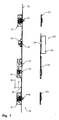
- the FIG. 1 shows a locking assembly 10.
- the locking assembly 10 has a base lock 11 with a latch 12 and a latch 13 and two secondary locks 14, 15, each with a latch 16, 17.
- the bars 13, 16, 17 are connected via a push rod 18 with each other. This means that by closing the wing, the bolt 13, 16, 17 extend automatically and thus locking takes place.
- the push rod 18 is moved in the direction of the arrow 20, are the latch 13, 16, 17 retracted.
- the case 12 is retracted and a wing on which the locks 11, 14, 15 are arranged, can be opened.
- the latch 13 and the latch 12 act together with a fixed frame side arranged latch-latch closing piece 21.
- the latch 16 cooperates with a closing piece 22 and the latch 17 with a fixed frame-side closing piece 23.
- a motor 25 is provided, via which a driver 26 is movable in the folding longitudinal direction.
- the motor 25 and the driver 26 constitute an unlocking device 27.
- an additional box 30 is provided, in which a latch 31 is arranged, which projects through the push rod 18 and forend 35. When the wing is closed and locked the latch 31 is above the driver 26.
- the driver 26 is now driven in unlocking 20, he takes the case 31 so that the push rod 18 is moved in unlocking 20 and the latch 13, 16, 17 retracted become.
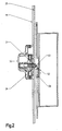
- the latch 31 lies in the closed position of the wing above the driver 26.
- the latch 31 has a driver stop 32.
- the driver 26 abuts against the driver stop 32 during a movement in Entrielgelungsraum, he takes the case 31 and thus the push rod 18 in the unlocking with.
- the driver 26 moves in normal operation automatically back to its basic position shown (unlocked). If the wing is then opened, the latch 31 reaches the position shown. Problems occur when the driver 26 is not moved to its home position 26 due to a fault. In this case, it may happen that the case 31 abuts against the dog 26 in a direction other than the unlocking direction.
- a plane inclined in the plane of the wing to the horizontal surface 33 causes the latch 31 is moved into the additional box 30 when the case 31 abuts from below against the driver 26 and the driver 26 abuts against the trap 31 from above.
- An inclined against the vertical or the wing plane slope 34 causes a displacement of the case 31 in the secondary box 30 when the case 31 abuts against the driver 26 side. It may be a further slope, which is formed analogously to the slope 34 on the other side of the case 31, may be provided.
- the restoring force can be exerted by a spring element, not shown here, via which the latch 31 is supported on the additional box 30. Characterized in that the case 31 is displaceable in the box 30, a manual or mechanical actuation of the locking arrangement is always guaranteed.
Landscapes
- Engineering & Computer Science (AREA)
- Mechanical Engineering (AREA)
- Lock And Its Accessories (AREA)
- Power-Operated Mechanisms For Wings (AREA)
Abstract
Description
- Die Erfindung betrifft eine Verriegelungsanordnung für eine Tür, ein Fenster oder dergleichen mit einem Hauptschloss und zumindest einem Nebenschloss, sowie einer mit einem Riegel des Hauptschlosses und/oder des Nebenschlosses zusammenwirkenden Schubstange, und mit einer Entriegelungseinrichtung, wobei die Entriegelungseinrichtung einen Motor zum Antrieb der Schubstange aufweist.
- Aus der
EP 0 942 135 B1 ist eine Verriegelungseinrichtung für eine Tür, ein Fenster oder dergleichen, mit einem Hauptschließkasten, wenigstens einem Zusatzschließkasten und wenigstens einer den Zusatzschließkasten mit dem Hauptschließkasten verbindenden Zugstange bekannt, wobei der Zusatzschließkasten einen beim Schließen der Tür, des Fensters oder dergleichen automatisch von einer Fallenstellung in eine Riegelstellung vorschließenden Fallenriegel aufweist. Die Zugstange ist mit einer Öffnungseinrichtung gekoppelt und die Öffnungseinrichtung weist einen Elektromotor zum Antrieb und zum Halten der Zugstange auf, wodurch der Fallenriegel in die Offenstellung zurückgezogen wird. Bei dieser Verriegelungseinrichtung ist die Öffnungseinrichtung fest mit der Zugstange gekoppelt. Dies bedeutet jedoch, dass die Öffnungseinrichtung ebenfalls im Flügel, der in der Regel die Zugstange aufweist, angeordnet sein muss. - Aus der
EP 1 283 318 A1 ist eine Verriegelungseinrichtung für eine einen Flügel aufweisende Tür bekannt. Die Verriegelungseinrichtung hat einen elektrischen Antrieb und einen mechanischen Antrieb für eine Treibstange. Die Treibstange hat einen mechanischen Antrieb zu ihrer Bewegung bei abgeschaltetem elektrischen Antrieb. Hierzu weisen die Koppelmittel einen Freibereich auf, in welchem die Treibstange ohne Mitnahme des elektrischen Antriebs bewegbar ist, wobei der Freibereich bei in einer Grundstellung befindlichem elektrischem Antrieb eine Bewegung der Treibstange in ihre beiden Stellungen ermöglicht. Wenn sich jedoch der elektrische Antrieb aufgrund einer Störung nicht in seiner Grundstellung befindet, kann eine Bewegung der Treibstange behindert werden. - Aufgabe der vorliegenden Erfindung ist es, eine Verriegelungsanordnung bereitzustellen, welche über einen elektromotorischen Antrieb entriegelt werden kann, wobei eine Betätigung der Verriegelungsanordnung bei gestörtem Antrieb stets gewährleistet ist.
- Gelöst wird diese Aufgabe durch eine Verriegelungsanordnung der eingangs genannten Art, wobei an der Schubstange eine Falle angeordnet ist, die einen Mitnehmeranschlag aufweist, an dem ein Mitnehmer der Entriegelungseinrichtung bei einer Bewegung des Mitnehmers in Entriegelungsrichtung anschlägt und die Falle mitsamt der Schubstange in Entriegelungsrichtung mitnimmt, wobei die Falle oder der Mitnehmer gegen eine Rückstellkraft verlagerbar angeordnet sind, so dass bei einem Aufeinandertreffen des Mitnehmers und der Falle zumindest in einer Richtung, die nicht der Entriegelungsrichtung entspricht, die Falle oder der Mitnehmer dem jeweils anderen Element ausweicht.
- Dadurch wird sichergestellt, dass die Verriegelungsanordnung zumindest mechanisch stets entriegelt werden kann. Befindet sich nämlich aufgrund einer Störung der Mitnehmer nicht in seiner Grundposition, so gibt entweder der Mitnehmer oder die Falle nach. Jedenfalls blockieren sich Mitnehmer und Falle nicht gegenseitig. Eine Blockierung der Schubstange ist somit ausgeschlossen.
- Vorzugsweise handelt es sich zumindest bei dem Nebenschloss um eine Automatikverriegelung. Dies bedeutet, dass beim Schließen eines Flügels einer Tür automatisch verriegelt wird. Der Motor der Entriegelungseinrichtung kann als Linearmotor ausgebildet sein. Weiterhin kann vorgesehen sein, dass an dem Motor ein Empfänger vorgesehen ist und der Motor über eine Fernbedienung gesteuert werden kann. Vorzugsweise ist die Entriegelungseinrichtung ausschließlich zum Entriegeln einsetzbar.
- Durch die erfindungsgemäße Verriegelungsanordnung wird die Benutzungssicherheit bei Stromausfall sichergestellt.
- Bei einer besonders bevorzugten Ausführungsform kann vorgesehen sein, dass die Falle zumindest eine Schräge aufweist. Dadurch kann sie, wenn sie gegen den Mitnehmer stößt, an dem Mitnehmer entlang gleiten und gleichzeitig gegen die Rückstellkraft bewegt werden. Das Ausweichen der Falle wird dadurch erleichtert.
- Besonders bevorzugt ist es, wenn die Falle eine zur Horizontalen, insbesondere in der Flügelebene, geneigte Schräge aufweist. Dadurch wird sichergestellt, dass die Falle gegen eine Rückstellkraft verdrängt wird, wenn entweder die Falle von unten gegen den Mitnehmer stößt oder wenn der Mitnehmer von oben gegen die Falle stößt.
- Bei einer Ausgestaltung kann vorgesehen sein, dass die Falle eine zur Vertikalen, insbesondere zur Flügelebene, geneigte Schräge aufweist. Dadurch wird ein Ausweichen der Falle erleichtert, wenn diese seitlich gegen den Mitnehmer stößt, beispielsweise, wenn der Mitnehmer nicht in seiner Grundstellung ist und der Flügel, an dem die Falle angeordnet ist, geschlossen wird. Es kann vorgesehen sein, dass die Falle zwei zur Vertikalen geneigte Flächen aufweist. Dies ermöglicht den Einbau links und rechts.
- Besonders bevorzugt ist es, wenn die Falle drei Schrägen aufweist. Dadurch wird ein Ausweichen der Falle sichergestellt, wenn sie von unten an den Mitnehmer stößt oder wenn sie seitlich an den Mitnehmer stößt.
- In diesem Zusammenhang ist es besonders vorteilhaft, wenn die Falle beim Auftreffen auf den Mitnehmer in mehreren Richtungen, insbesondere in drei Richtungen, gegen eine Rückstellkraft bewegbar ist. Sie kann somit dem Mitnehmer stets ausweichen, wenn sie in einer anderen Richtung als der Entriegelungsrichtung mit dem Mitnehmer in Kontakt kommt. Die Rückstellkraft bewirkt, dass nach einem Kontakt mit dem Mitnehmer die Falle stets in ihre Ausgangslage zurückbewegt wird und bei ordnungsgemäß arbeitendem Antrieb sofort wieder einsetzbar ist.
- Im Normalbetrieb wird eine Kollision der Falle mit dem Mitnehmer verhindert, wenn eine Steuerung für den Motor vorgesehen ist, die bewirkt, dass der Mitnehmer nach einer Entriegelung stets in seine Ausgangsposition (Grundstellung) zurückbewegt wird.
- Weitere Vorteile ergeben sich, wenn die Falle flügelseitig angeordnet ist und der Motor der Entriegelungseinrichtung festrahmenseitig angeordnet ist. Eine feste Verbindung zwischen Falle und Entriegelungseinrichtung ist nicht notwendig und im vorliegenden Fall auch nicht erwünscht. Das Vorsehen des Motors auf der Festrahmenseite hat den Vorteil, dass dieser einfach an ein Stromversorgungsnetz angeschlossen werden kann. Wäre der Motor im oder am Flügel befestigt, müsste der Falz überbrückt werden, um den Motor mit Strom zu versorgen. Es ist jedoch auch denkbar, den Motor über Akku oder Batterie zu betreiben.
- Weitere Vorteile ergeben sich, wenn die Falle in einen Zusatzkasten angeordnet ist. In dem Zusatzkasten kann sich die Falle über ein oder mehrere Federelemente abstützen, so dass sie gegen Rückstellkräfte bewegbar ist. Ein separater Zusatzkasten kann nachträglich installiert werden.
- In den Rahmen der Erfindung fällt außerdem ein Fenster, eine Tür oder dergleichen mit einer erfindungsgemäßen Verriegelungsanordnung.
- Weitere Merkmale und Vorteile der Erfindung ergeben sich aus der nachfolgenden detaillierten Beschreibung eines Ausführungsbeispiels der Erfindung, anhand der Figuren der Zeichnung, die erfindungswesentliche Einzelheiten zeigt, sowie aus den Ansprüchen. Die dort gezeigten Merkmale sind nicht notwendig maßstäblich zu verstehen und derart dargestellt, dass die erfindungsgemäßen Besonderheiten deutlich sichtbar gemacht werden können. Die verschiedenen Merkmale können je einzeln für sich oder zu mehreren in beliebigen Kombinationen bei Varianten der Erfindung verwirklicht sein.
- In der schematischen Zeichnung ist ein Ausführungsbeispiel der Erfindung dargestellt und in der nachfolgenden Beschreibung näher erläutert.
- Es zeigen :
- Fig. 1
- eine erfindungsgemäße Verriegelungsanordnung;
- Fig. 2
- eine Entriegelungseinrichtung.
- Die
Figur 1 zeigt eine Verriegelungsanordnung 10. Die Verriegelungsanordnung 10 weist ein Basisschloss 11 mit einer Falle 12 und einem Riegel 13 sowie zwei Nebenschlösser 14, 15 mit jeweils einem Riegel 16, 17 auf. Die Riegel 13, 16, 17 stehen über eine Schubstange 18 miteinander in Verbindung. Dies bedeutet, dass durch das Schließen des Flügels die Riegel 13, 16, 17 automatisch ausfahren und somit eine Verriegelung erfolgt. Wird die Schubstange 18 dagegen in Pfeilrichtung 20 bewegt, werden die Riegel 13, 16, 17 eingefahren. Zudem kann vorgesehen sein, dass in diesem Fall auch die Falle 12 eingefahren wird und ein Flügel, an dem die Schlösser 11, 14, 15 angeordnet sind, geöffnet werden kann. Der Riegel 13 und die Falle 12 wirken dabei mit einem festrahmenseitig angeordneten Fallen-Riegelschließstück 21 zusammen. Der Riegel 16 wirkt mit einem Schließstück 22 und der Riegel 17 mit einem festrahmenseitigen Schließstück 23 zusammen. Festrahmenseitig ist ein Motor 25 vorgesehen, über den ein Mitnehmer 26 in Falzlängsrichtung bewegbar ist. Der Motor 25 und der Mitnehmer 26 stellen eine Entriegelungseinrichtung 27 dar. Auf der gegenüberliegenden Seite am Flügel ist ein Zusatzkasten 30 vorgesehen, in dem eine Falle 31 angeordnet ist, die die Schubstange 18 und Stulp 35 durchragt. Bei geschlossenem und verriegeltem Flügel liegt die Falle 31 über dem Mitnehmer 26. Wenn der Mitnehmer 26 nun in Entriegelungsrichtung 20 angetrieben wird, nimmt er die Falle 31 mit, sodass die Schubstange 18 in Entriegelungsrichtung 20 bewegt wird und die Riegel 13, 16, 17 eingefahren werden. - Anhand der
Figur 2 wird die Entriegelungseinrichtung näher beschrieben. Wie bereits erwähnt, liegt die Falle 31 in der Geschlossenstellung des Flügels oberhalb des Mitnehmers 26. Die Falle 31 weist einen Mitnehmeranschlag 32 auf. Wenn der Mitnehmer 26 an den Mitnehmeranschlag 32 bei einer Bewegung in Entrielgelungsrichtung anschlägt, nimmt er die Falle 31 und somit die Schubstange 18 in Entriegelungsrichtung mit. Nach der Entriegelung bewegt sich der Mitnehmer 26 im Normalbetrieb automatisch wieder in seine gezeigte Grundstellung zurück (entriegelt). Wird anschließend der Flügel geöffnet, gelangt die Falle 31 in die gezeigte Stellung. Probleme treten auf, wenn der Mitnehmer 26 aufgrund einer Störung nicht in seine Grundstellung 26 bewegt wird. In diesem Fall kann es vorkommen, dass die Falle 31 in einer anderen Richtung als der Entriegelungsrichtung gegen den Mitnehmer 26 stößt. Um eine Funktion der Verriegelungsanordnung dennoch zu gewährleisten, ist vorgesehen, dass die Falle 31 gegen eine Rückstellkraft in den Zusatzkasten 30 bewegbar ist. Eine in der Flügelebene zur Horizontalen geneigte Fläche 33 bewirkt, dass die Falle 31 in den Zusatzkasten 30 bewegt wird, wenn die Falle 31 von unten gegen den Mitnehmer 26 stößt bzw. der Mitnehmer 26 von oben gegen die Falle 31 stößt. Eine gegen die Vertikale bzw. zur Flügelebene geneigte Schräge 34 bewirkt ein Verdrängen der Falle 31 in den Nebenkasten 30, wenn die Falle 31 seitlich gegen den Mitnehmer 26 stößt. Es kann eine weitere Schräge, die analog zur Schräge 34 auf der anderen Seite der Falle 31 ausgebildet ist, vorgesehen sein. Dies bedeutet, dass die Falle 31 ein keilförmiges, spitzes freies Ende aufweist. Die Rückstellkraft kann durch ein hier nicht gezeigtes Federelement ausgeübt werden, über welches sich die Falle 31 am Zusatzkasten 30 abstützt. Dadurch, dass die Falle 31 in den Kasten 30 verdrängbar ist, ist eine manuelle bzw. mechanische Betätigung der Verriegelungsanordnung stets gewährleistet.
Claims (10)
- Verriegelungsanordnung (10) für eine Tür, ein Fenster oder dgl. mit einem Hauptschloss (11) und zumindest einem Nebenschloss (14, 15), sowie einer mit einem Riegel (13, 16, 17) des Hauptschlosses (11) und/oder des Nebenschlosses (14, 15) zusammenwirkenden Schubstange (18) und mit einer Entriegelungseinrichtung (27), wobei die Entriegelungseinrichtung (27) einen Motor (25) zum Antrieb der Schubstange (18) aufweist, dadurch gekennzeichnet, dass an der Schubstange (18) eine Falle (31) angeordnet ist, die einen Mitnehmeranschlag (32) aufweist, an dem ein Mitnehmer (26) der Entriegelungseinrichtung (27) bei einer Bewegung des Mitnehmers (26) in Entriegelungsrichtung (20) anschlägt und die Falle (31) mitsamt der Schubstange (18) in Entriegelungsrichtung (20) mitnimmt, wobei die Falle (31) oder der Mitnehmer (26) gegen eine Rückstellkraft verlagerbar angeordnet ist, so dass bei einem Aufeinandertreffen des Mitnehmers (26) und der Falle (31) zumindest in einer Richtung, die nicht der Entriegelungsrichtung (20) entspricht, die Falle (31) oder der Mitnehmer (26) dem jeweils anderen Element ausweicht.
- Verriegelungsanordnung nach Anspruch 1, dadurch gekennzeichnet, dass die Falle (31) zumindest eine Schräge (33, 34) aufweist.
- Verriegelungsanordnung nach einem der vorhergehenden Ansprüche, dadurch gekennzeichnet, dass die Falle (31) eine zur Horizontalen geneigte Schräge (33) aufweist.
- Verriegelungsanordnung nach einem der vorhergehenden Ansprüche, dadurch gekennzeichnet, dass die Falle (31) eine zur Vertikalen geneigte Schräge (34) aufweist.
- Verriegelungsanordnung nach einem der vorhergehenden Ansprüche, dadurch gekennzeichnet, dass die Falle (31) drei Schrägen (33,34) aufweist.
- Verriegelungsanordnung nach einem der vorhergehenden Ansprüche, dadurch gekennzeichnet, dass die Falle (31) beim Auftreffen auf den Mitnehmer (26) in mehreren Richtungen, insbesondere drei Richtungen, gegen eine Rückstellkraft bewegbar ist.
- Verriegelungsanordnung nach einem der vorhergehenden Ansprüche, dadurch gekennzeichnet, dass eine Steuerung für den Motor vorgesehen ist, die bewirkt, dass der Mitnehmer (26) nach einer Entriegelung stets in seine Ausgangsposition zurück bewegt wird.
- Verriegelungsanordnung nach einem der vorhergehenden Ansprüche, dadurch gekennzeichnet, dass die Falle (31) flügelseitig angeordnet ist und der Motor der Entriegelungseinrichtung (27) festrahmenseitig angeordnet ist.
- Verriegelungsanordnung nach einem der vorhergehenden Ansprüche, dadurch gekennzeichnet, dass die Falle (31) in einem Zusatzkasten (30) angeordnet ist.
- Fenster, Tür oder dgl. mit einer Verriegelungsanordnung (10) nach einem der vorhergehenden Ansprüche.
Priority Applications (1)
| Application Number | Priority Date | Filing Date | Title |
|---|---|---|---|
| PL09002910T PL2101020T3 (pl) | 2008-03-15 | 2009-02-28 | Układ ryglujący |
Applications Claiming Priority (1)
| Application Number | Priority Date | Filing Date | Title |
|---|---|---|---|
| DE102008014548.3A DE102008014548B4 (de) | 2008-03-15 | 2008-03-15 | Verriegelungsanordnung |
Publications (3)
| Publication Number | Publication Date |
|---|---|
| EP2101020A2 true EP2101020A2 (de) | 2009-09-16 |
| EP2101020A3 EP2101020A3 (de) | 2011-07-13 |
| EP2101020B1 EP2101020B1 (de) | 2012-12-05 |
Family
ID=40718890
Family Applications (1)
| Application Number | Title | Priority Date | Filing Date |
|---|---|---|---|
| EP09002910A Not-in-force EP2101020B1 (de) | 2008-03-15 | 2009-02-28 | Verriegelungsanordnung |
Country Status (3)
| Country | Link |
|---|---|
| EP (1) | EP2101020B1 (de) |
| DE (1) | DE102008014548B4 (de) |
| PL (1) | PL2101020T3 (de) |
Cited By (1)
| Publication number | Priority date | Publication date | Assignee | Title |
|---|---|---|---|---|
| EP2921616B1 (de) | 2014-03-18 | 2017-07-19 | Gretsch-Unitas GmbH Baubeschläge | Anordnung für einen Flucht- oder Notausgang |
Citations (2)
| Publication number | Priority date | Publication date | Assignee | Title |
|---|---|---|---|---|
| EP1283318A1 (de) | 2001-08-11 | 2003-02-12 | Aug. Winkhaus GmbH & Co. KG | Verriegelungseinrichtung |
| EP0942135B1 (de) | 1998-02-23 | 2003-03-12 | Gretsch-Unitas GmbH Baubeschläge | Verriegelungseinrichtung |
Family Cites Families (4)
| Publication number | Priority date | Publication date | Assignee | Title |
|---|---|---|---|---|
| DE10024952A1 (de) * | 2000-05-22 | 2001-11-29 | Fliether Karl Gmbh & Co | Elektromotorisch angetriebener Verschluss |
| DE20203565U1 (de) * | 2002-02-27 | 2002-05-23 | Gretsch-Unitas GmbH Baubeschläge, 71254 Ditzingen | Schließvorrichtung |
| DE10308243B4 (de) * | 2003-02-25 | 2006-11-02 | Carl Fuhr Gmbh & Co. Kg | Schließanlage, insbesondere Türverschluss, Fensterverschluss oder dergleichen |
| DE10359804A1 (de) * | 2003-12-19 | 2005-07-14 | Aug. Winkhaus Gmbh & Co. Kg | Antriebseinrichtung für einen Treibstangenbeschlag |
-
2008
- 2008-03-15 DE DE102008014548.3A patent/DE102008014548B4/de not_active Expired - Fee Related
-
2009
- 2009-02-28 EP EP09002910A patent/EP2101020B1/de not_active Not-in-force
- 2009-02-28 PL PL09002910T patent/PL2101020T3/pl unknown
Patent Citations (2)
| Publication number | Priority date | Publication date | Assignee | Title |
|---|---|---|---|---|
| EP0942135B1 (de) | 1998-02-23 | 2003-03-12 | Gretsch-Unitas GmbH Baubeschläge | Verriegelungseinrichtung |
| EP1283318A1 (de) | 2001-08-11 | 2003-02-12 | Aug. Winkhaus GmbH & Co. KG | Verriegelungseinrichtung |
Cited By (1)
| Publication number | Priority date | Publication date | Assignee | Title |
|---|---|---|---|---|
| EP2921616B1 (de) | 2014-03-18 | 2017-07-19 | Gretsch-Unitas GmbH Baubeschläge | Anordnung für einen Flucht- oder Notausgang |
Also Published As
| Publication number | Publication date |
|---|---|
| EP2101020A3 (de) | 2011-07-13 |
| EP2101020B1 (de) | 2012-12-05 |
| DE102008014548B4 (de) | 2014-12-04 |
| PL2101020T3 (pl) | 2013-05-31 |
| DE102008014548A1 (de) | 2009-09-17 |
Similar Documents
| Publication | Publication Date | Title |
|---|---|---|
| EP0942135B2 (de) | Verriegelungseinrichtung | |
| EP2264268B2 (de) | Treibriegelschloss | |
| DE3135401C2 (de) | Verriegelungseinrichtung für ein Tor mit einem ein- oder mehrteiligen Torblatt | |
| EP1340871B1 (de) | Schliessvorrichtung | |
| EP1936075A2 (de) | Selbstverriegelndes, elektromechanisches Panikschloss | |
| EP2146032B1 (de) | Vorrichtung zum Öffnen und/oder Schliessen sowie zum Verriegeln eines geschlossenen Zustandes einer Verschlusseinrichtung zum Verschliessen einer Raumöffnung sowie Verschlusseinrichtung mit einer solchen Vorrichtung | |
| EP2752539B2 (de) | Treibriegelschloss | |
| DE202010011704U1 (de) | Sicherungsvorrichtung | |
| EP0433623A2 (de) | Verriegelungsvorrichtung für ein Fenster, eine Tür od.dgl. | |
| DE29619007U1 (de) | Verriegelungsvorrichtung | |
| EP2339096A2 (de) | Treibstangenschloss mit Panikfunktion und Mehrfachverriegelung | |
| DE102015000606A1 (de) | Verriegelungsvorrichtung für einen schwenkbar gelagerten Flügel | |
| EP3162995B1 (de) | Beschlagteil eines beschlages für einen flügel eines fensters oder einer tür | |
| EP2101020B1 (de) | Verriegelungsanordnung | |
| EP2543798B1 (de) | Selbstverriegelndes Schloss | |
| DE20305650U1 (de) | Schloss | |
| WO2009095032A1 (de) | Sicherheitsschalter mit zuhaltungsfunktion zum zwangsöffnung von kontaktelementen sowie verfahren zum zwangsöffnen von kontaktelementen eines sicherheitsschalters mit verriegelungsfunktion | |
| EP1936073A2 (de) | Selbstverriegelndes Panikschloss | |
| DE102012200640A1 (de) | Antriebsvorrichtung für eine gemeinsame Betätigung eines Zentralverschlusses und des Flügels eines Fensters oder einer Türe | |
| EP3744929B1 (de) | Stangenverschluss | |
| EP2453086B1 (de) | Treibstangenbeschlag für Standflügel von zweiflügeligen Fenstern oder Türen ohne Mittelpfosten | |
| EP3655601B1 (de) | Schloss | |
| EP2806090A2 (de) | Vorrichtung zum Verriegeln oder Entriegeln eines Schiebeflügels | |
| DE10147989B4 (de) | Schaltschrank | |
| EP3744932B1 (de) | Stangenverschluss mit notentriegelung |
Legal Events
| Date | Code | Title | Description |
|---|---|---|---|
| PUAI | Public reference made under article 153(3) epc to a published international application that has entered the european phase |
Free format text: ORIGINAL CODE: 0009012 |
|
| AK | Designated contracting states |
Kind code of ref document: A2 Designated state(s): AT BE BG CH CY CZ DE DK EE ES FI FR GB GR HR HU IE IS IT LI LT LU LV MC MK MT NL NO PL PT RO SE SI SK TR |
|
| AX | Request for extension of the european patent |
Extension state: AL BA RS |
|
| PUAL | Search report despatched |
Free format text: ORIGINAL CODE: 0009013 |
|
| AK | Designated contracting states |
Kind code of ref document: A3 Designated state(s): AT BE BG CH CY CZ DE DK EE ES FI FR GB GR HR HU IE IS IT LI LT LU LV MC MK MT NL NO PL PT RO SE SI SK TR |
|
| AX | Request for extension of the european patent |
Extension state: AL BA RS |
|
| RIC1 | Information provided on ipc code assigned before grant |
Ipc: E05B 47/00 20060101ALI20110609BHEP Ipc: E05C 9/02 20060101ALI20110609BHEP Ipc: E05C 9/00 20060101ALI20110609BHEP Ipc: E05C 9/10 20060101AFI20090615BHEP |
|
| 17P | Request for examination filed |
Effective date: 20110817 |
|
| AKX | Designation fees paid |
Designated state(s): AT BE BG CH CY CZ DE DK EE ES FI FR GB GR HR HU IE IS IT LI LT LU LV MC MK MT NL NO PL PT RO SE SI SK TR |
|
| GRAP | Despatch of communication of intention to grant a patent |
Free format text: ORIGINAL CODE: EPIDOSNIGR1 |
|
| RIC1 | Information provided on ipc code assigned before grant |
Ipc: E05C 9/00 20060101ALI20120626BHEP Ipc: E05C 9/10 20060101AFI20120626BHEP Ipc: E05B 47/00 20060101ALI20120626BHEP Ipc: E05C 9/02 20060101ALI20120626BHEP |
|
| GRAS | Grant fee paid |
Free format text: ORIGINAL CODE: EPIDOSNIGR3 |
|
| GRAA | (expected) grant |
Free format text: ORIGINAL CODE: 0009210 |
|
| AK | Designated contracting states |
Kind code of ref document: B1 Designated state(s): AT BE BG CH CY CZ DE DK EE ES FI FR GB GR HR HU IE IS IT LI LT LU LV MC MK MT NL NO PL PT RO SE SI SK TR |
|
| REG | Reference to a national code |
Ref country code: GB Ref legal event code: FG4D Free format text: NOT ENGLISH |
|
| REG | Reference to a national code |
Ref country code: CH Ref legal event code: EP |
|
| REG | Reference to a national code |
Ref country code: AT Ref legal event code: REF Ref document number: 587393 Country of ref document: AT Kind code of ref document: T Effective date: 20121215 |
|
| REG | Reference to a national code |
Ref country code: IE Ref legal event code: FG4D Free format text: LANGUAGE OF EP DOCUMENT: GERMAN |
|
| REG | Reference to a national code |
Ref country code: DE Ref legal event code: R096 Ref document number: 502009005544 Country of ref document: DE Effective date: 20130131 |
|
| PG25 | Lapsed in a contracting state [announced via postgrant information from national office to epo] |
Ref country code: FI Free format text: LAPSE BECAUSE OF FAILURE TO SUBMIT A TRANSLATION OF THE DESCRIPTION OR TO PAY THE FEE WITHIN THE PRESCRIBED TIME-LIMIT Effective date: 20121205 Ref country code: LT Free format text: LAPSE BECAUSE OF FAILURE TO SUBMIT A TRANSLATION OF THE DESCRIPTION OR TO PAY THE FEE WITHIN THE PRESCRIBED TIME-LIMIT Effective date: 20121205 Ref country code: ES Free format text: LAPSE BECAUSE OF FAILURE TO SUBMIT A TRANSLATION OF THE DESCRIPTION OR TO PAY THE FEE WITHIN THE PRESCRIBED TIME-LIMIT Effective date: 20130316 Ref country code: NO Free format text: LAPSE BECAUSE OF FAILURE TO SUBMIT A TRANSLATION OF THE DESCRIPTION OR TO PAY THE FEE WITHIN THE PRESCRIBED TIME-LIMIT Effective date: 20130305 Ref country code: HR Free format text: LAPSE BECAUSE OF FAILURE TO SUBMIT A TRANSLATION OF THE DESCRIPTION OR TO PAY THE FEE WITHIN THE PRESCRIBED TIME-LIMIT Effective date: 20121205 Ref country code: SE Free format text: LAPSE BECAUSE OF FAILURE TO SUBMIT A TRANSLATION OF THE DESCRIPTION OR TO PAY THE FEE WITHIN THE PRESCRIBED TIME-LIMIT Effective date: 20121205 |
|
| REG | Reference to a national code |
Ref country code: NL Ref legal event code: VDEP Effective date: 20121205 |
|
| REG | Reference to a national code |
Ref country code: LT Ref legal event code: MG4D |
|
| PG25 | Lapsed in a contracting state [announced via postgrant information from national office to epo] |
Ref country code: LV Free format text: LAPSE BECAUSE OF FAILURE TO SUBMIT A TRANSLATION OF THE DESCRIPTION OR TO PAY THE FEE WITHIN THE PRESCRIBED TIME-LIMIT Effective date: 20121205 Ref country code: SI Free format text: LAPSE BECAUSE OF FAILURE TO SUBMIT A TRANSLATION OF THE DESCRIPTION OR TO PAY THE FEE WITHIN THE PRESCRIBED TIME-LIMIT Effective date: 20121205 Ref country code: CY Free format text: LAPSE BECAUSE OF FAILURE TO SUBMIT A TRANSLATION OF THE DESCRIPTION OR TO PAY THE FEE WITHIN THE PRESCRIBED TIME-LIMIT Effective date: 20121205 Ref country code: GR Free format text: LAPSE BECAUSE OF FAILURE TO SUBMIT A TRANSLATION OF THE DESCRIPTION OR TO PAY THE FEE WITHIN THE PRESCRIBED TIME-LIMIT Effective date: 20130306 |
|
| REG | Reference to a national code |
Ref country code: PL Ref legal event code: T3 |
|
| PG25 | Lapsed in a contracting state [announced via postgrant information from national office to epo] |
Ref country code: BG Free format text: LAPSE BECAUSE OF FAILURE TO SUBMIT A TRANSLATION OF THE DESCRIPTION OR TO PAY THE FEE WITHIN THE PRESCRIBED TIME-LIMIT Effective date: 20130305 Ref country code: EE Free format text: LAPSE BECAUSE OF FAILURE TO SUBMIT A TRANSLATION OF THE DESCRIPTION OR TO PAY THE FEE WITHIN THE PRESCRIBED TIME-LIMIT Effective date: 20121205 Ref country code: IS Free format text: LAPSE BECAUSE OF FAILURE TO SUBMIT A TRANSLATION OF THE DESCRIPTION OR TO PAY THE FEE WITHIN THE PRESCRIBED TIME-LIMIT Effective date: 20130405 Ref country code: SK Free format text: LAPSE BECAUSE OF FAILURE TO SUBMIT A TRANSLATION OF THE DESCRIPTION OR TO PAY THE FEE WITHIN THE PRESCRIBED TIME-LIMIT Effective date: 20121205 |
|
| PG25 | Lapsed in a contracting state [announced via postgrant information from national office to epo] |
Ref country code: PT Free format text: LAPSE BECAUSE OF FAILURE TO SUBMIT A TRANSLATION OF THE DESCRIPTION OR TO PAY THE FEE WITHIN THE PRESCRIBED TIME-LIMIT Effective date: 20130405 Ref country code: RO Free format text: LAPSE BECAUSE OF FAILURE TO SUBMIT A TRANSLATION OF THE DESCRIPTION OR TO PAY THE FEE WITHIN THE PRESCRIBED TIME-LIMIT Effective date: 20121205 Ref country code: NL Free format text: LAPSE BECAUSE OF FAILURE TO SUBMIT A TRANSLATION OF THE DESCRIPTION OR TO PAY THE FEE WITHIN THE PRESCRIBED TIME-LIMIT Effective date: 20121205 |
|
| BERE | Be: lapsed |
Owner name: ROTO FRANK A.G. Effective date: 20130228 |
|
| PG25 | Lapsed in a contracting state [announced via postgrant information from national office to epo] |
Ref country code: MC Free format text: LAPSE BECAUSE OF NON-PAYMENT OF DUE FEES Effective date: 20130228 |
|
| REG | Reference to a national code |
Ref country code: CH Ref legal event code: PL |
|
| PLBE | No opposition filed within time limit |
Free format text: ORIGINAL CODE: 0009261 |
|
| STAA | Information on the status of an ep patent application or granted ep patent |
Free format text: STATUS: NO OPPOSITION FILED WITHIN TIME LIMIT |
|
| PG25 | Lapsed in a contracting state [announced via postgrant information from national office to epo] |
Ref country code: DK Free format text: LAPSE BECAUSE OF FAILURE TO SUBMIT A TRANSLATION OF THE DESCRIPTION OR TO PAY THE FEE WITHIN THE PRESCRIBED TIME-LIMIT Effective date: 20121205 Ref country code: LI Free format text: LAPSE BECAUSE OF NON-PAYMENT OF DUE FEES Effective date: 20130228 Ref country code: CH Free format text: LAPSE BECAUSE OF NON-PAYMENT OF DUE FEES Effective date: 20130228 |
|
| 26N | No opposition filed |
Effective date: 20130906 |
|
| GBPC | Gb: european patent ceased through non-payment of renewal fee |
Effective date: 20130305 |
|
| REG | Reference to a national code |
Ref country code: IE Ref legal event code: MM4A |
|
| PG25 | Lapsed in a contracting state [announced via postgrant information from national office to epo] |
Ref country code: IT Free format text: LAPSE BECAUSE OF FAILURE TO SUBMIT A TRANSLATION OF THE DESCRIPTION OR TO PAY THE FEE WITHIN THE PRESCRIBED TIME-LIMIT Effective date: 20121205 |
|
| REG | Reference to a national code |
Ref country code: DE Ref legal event code: R097 Ref document number: 502009005544 Country of ref document: DE Effective date: 20130906 |
|
| PG25 | Lapsed in a contracting state [announced via postgrant information from national office to epo] |
Ref country code: BE Free format text: LAPSE BECAUSE OF NON-PAYMENT OF DUE FEES Effective date: 20130228 Ref country code: IE Free format text: LAPSE BECAUSE OF NON-PAYMENT OF DUE FEES Effective date: 20130228 Ref country code: GB Free format text: LAPSE BECAUSE OF NON-PAYMENT OF DUE FEES Effective date: 20130305 |
|
| PG25 | Lapsed in a contracting state [announced via postgrant information from national office to epo] |
Ref country code: MT Free format text: LAPSE BECAUSE OF FAILURE TO SUBMIT A TRANSLATION OF THE DESCRIPTION OR TO PAY THE FEE WITHIN THE PRESCRIBED TIME-LIMIT Effective date: 20121205 |
|
| PG25 | Lapsed in a contracting state [announced via postgrant information from national office to epo] |
Ref country code: HU Free format text: LAPSE BECAUSE OF FAILURE TO SUBMIT A TRANSLATION OF THE DESCRIPTION OR TO PAY THE FEE WITHIN THE PRESCRIBED TIME-LIMIT; INVALID AB INITIO Effective date: 20090228 Ref country code: MK Free format text: LAPSE BECAUSE OF FAILURE TO SUBMIT A TRANSLATION OF THE DESCRIPTION OR TO PAY THE FEE WITHIN THE PRESCRIBED TIME-LIMIT Effective date: 20121205 Ref country code: LU Free format text: LAPSE BECAUSE OF NON-PAYMENT OF DUE FEES Effective date: 20130228 |
|
| REG | Reference to a national code |
Ref country code: FR Ref legal event code: PLFP Year of fee payment: 8 |
|
| REG | Reference to a national code |
Ref country code: FR Ref legal event code: PLFP Year of fee payment: 9 |
|
| PGFP | Annual fee paid to national office [announced via postgrant information from national office to epo] |
Ref country code: PL Payment date: 20170201 Year of fee payment: 9 Ref country code: CZ Payment date: 20170227 Year of fee payment: 9 |
|
| PGFP | Annual fee paid to national office [announced via postgrant information from national office to epo] |
Ref country code: TR Payment date: 20170224 Year of fee payment: 9 |
|
| REG | Reference to a national code |
Ref country code: FR Ref legal event code: PLFP Year of fee payment: 10 |
|
| PG25 | Lapsed in a contracting state [announced via postgrant information from national office to epo] |
Ref country code: CZ Free format text: LAPSE BECAUSE OF NON-PAYMENT OF DUE FEES Effective date: 20180228 |
|
| PG25 | Lapsed in a contracting state [announced via postgrant information from national office to epo] |
Ref country code: PL Free format text: LAPSE BECAUSE OF NON-PAYMENT OF DUE FEES Effective date: 20180228 |
|
| PGFP | Annual fee paid to national office [announced via postgrant information from national office to epo] |
Ref country code: DE Payment date: 20200225 Year of fee payment: 12 Ref country code: AT Payment date: 20200218 Year of fee payment: 12 |
|
| PGFP | Annual fee paid to national office [announced via postgrant information from national office to epo] |
Ref country code: FR Payment date: 20200220 Year of fee payment: 12 |
|
| REG | Reference to a national code |
Ref country code: DE Ref legal event code: R119 Ref document number: 502009005544 Country of ref document: DE |
|
| REG | Reference to a national code |
Ref country code: AT Ref legal event code: MM01 Ref document number: 587393 Country of ref document: AT Kind code of ref document: T Effective date: 20210228 |
|
| PG25 | Lapsed in a contracting state [announced via postgrant information from national office to epo] |
Ref country code: AT Free format text: LAPSE BECAUSE OF NON-PAYMENT OF DUE FEES Effective date: 20210228 |
|
| PG25 | Lapsed in a contracting state [announced via postgrant information from national office to epo] |
Ref country code: DE Free format text: LAPSE BECAUSE OF NON-PAYMENT OF DUE FEES Effective date: 20210901 Ref country code: FR Free format text: LAPSE BECAUSE OF NON-PAYMENT OF DUE FEES Effective date: 20210228 |
|
| PG25 | Lapsed in a contracting state [announced via postgrant information from national office to epo] |
Ref country code: TR Free format text: LAPSE BECAUSE OF NON-PAYMENT OF DUE FEES Effective date: 20180228 |