EP2100831A1 - Véhicule de transport pour palettes et système de transport - Google Patents
Véhicule de transport pour palettes et système de transport Download PDFInfo
- Publication number
- EP2100831A1 EP2100831A1 EP09002978A EP09002978A EP2100831A1 EP 2100831 A1 EP2100831 A1 EP 2100831A1 EP 09002978 A EP09002978 A EP 09002978A EP 09002978 A EP09002978 A EP 09002978A EP 2100831 A1 EP2100831 A1 EP 2100831A1
- Authority
- EP
- European Patent Office
- Prior art keywords
- trolley
- pallets
- transport
- loading
- drive
- Prior art date
- Legal status (The legal status is an assumption and is not a legal conclusion. Google has not performed a legal analysis and makes no representation as to the accuracy of the status listed.)
- Granted
Links
- 238000005516 engineering process Methods 0.000 claims description 4
- 238000000034 method Methods 0.000 claims description 4
- 230000008569 process Effects 0.000 claims description 4
- 238000012937 correction Methods 0.000 description 5
- 238000001514 detection method Methods 0.000 description 4
- 230000008859 change Effects 0.000 description 3
- 230000000630 rising effect Effects 0.000 description 2
- 230000004888 barrier function Effects 0.000 description 1
- 238000000151 deposition Methods 0.000 description 1
- 230000000694 effects Effects 0.000 description 1
- 230000004044 response Effects 0.000 description 1
- 230000001360 synchronised effect Effects 0.000 description 1
- 230000007704 transition Effects 0.000 description 1
- 230000001960 triggered effect Effects 0.000 description 1
Images


Classifications
-
- B—PERFORMING OPERATIONS; TRANSPORTING
- B65—CONVEYING; PACKING; STORING; HANDLING THIN OR FILAMENTARY MATERIAL
- B65G—TRANSPORT OR STORAGE DEVICES, e.g. CONVEYORS FOR LOADING OR TIPPING, SHOP CONVEYOR SYSTEMS OR PNEUMATIC TUBE CONVEYORS
- B65G67/00—Loading or unloading vehicles
- B65G67/02—Loading or unloading land vehicles
- B65G67/04—Loading land vehicles
- B65G67/20—Loading covered vehicles
-
- B—PERFORMING OPERATIONS; TRANSPORTING
- B65—CONVEYING; PACKING; STORING; HANDLING THIN OR FILAMENTARY MATERIAL
- B65G—TRANSPORT OR STORAGE DEVICES, e.g. CONVEYORS FOR LOADING OR TIPPING, SHOP CONVEYOR SYSTEMS OR PNEUMATIC TUBE CONVEYORS
- B65G7/00—Devices for assisting manual moving or tilting heavy loads
- B65G7/02—Devices adapted to be interposed between loads and the ground or floor, e.g. crowbars with means for assisting conveyance of loads
- B65G7/04—Rollers
Definitions
- the invention relates to a trolley for pallets with a support rail, at least two support rollers, a lifting drive for the support rail and a traction drive.
- the invention also relates to a transport system for pallets with at least two trolleys according to the invention.
- Known dolly for pallets have two mutually parallel support rails, which are interconnected in the region of a drive and lifting block. By means of the support rails, a pallet can be driven under and after lifting the support rails pallet can then be traversed.
- transport vehicles which are available as hand-operated or electrically operated pallet truck
- a pallet must first be placed on the mounting rails, lifted and then brought to their destination, for example in the loading compartment of a truck.
- transfer points are located in the extension of a loading ramp to which a truck is then placed with the rear side. Starting from the transfer point, the pallets can then be driven into the hold by means of known transport vehicles. In conventional trolleys, this basically requires a turning maneuver, since the transfer station is indeed arranged opposite the loading ramp. The loading of pallets by means of known transport vehicles is therefore not readily automatable.
- a trolley for pallets and a transport system for pallets to be provided, which allows the automatic loading of pallets in a simple way.
- the automatic loading and unloading of trucks is to be made possible whose cargo holds no special, tuned to the transport system according to the invention devices.
- a trolley for pallets with a support rail, at least two support rollers, a lifting drive for the mounting rail and a traction drive provided in which the trolley is suitable for driving underneath of pallets over its entire length and in which the at least two support rollers, the linear actuator and the traction drive between a defined by the Aufstandss, the support rollers roadway level and an upper side of the support rail are arranged.
- the trolley can pass completely below a pallet at least in the lowered state. This allows the trolley for loading pallets with a first end ahead undercut a pallet, then lift the pallet and transport to its destination and again drive out with the first end ahead under the pallet. It is thereby possible to transport pallets from a transfer station linearly and without turning maneuver the trolley on the back of a truck. Since the trolley is so shallow in its lowered position that it can go under its full length a pallet, the pallets can be parked on the back of the truck and the trolley can opposite to the retraction again extend.
- the trolley according to the invention thus creates the conditions for an automatic loading of pallets, in which between the lifting of the pallets at a transfer station and the settling of the pallets on the back of a truck, or vice versa, no turning maneuvers of the trolley are required.
- the trolley according to the invention allows to accomplish an automatic loading in trucks, which are not tuned in a special way on the trolley according to the invention.
- the trolley according to the invention can travel on a normal road, so that it can also drive onto the back of a truck and settle there pallets or can accommodate.
- the mounting rail in the plan view of an elongated, rectangular shape, which tapers at both ends.
- the support rail has a self-centering shape at both ends and can be easily moved under a pallet even with slight lateral offset.
- the support rail has a U-shaped cross-section, wherein a base of the U-shape form an upper side and the legs projecting downwards side skirts of the support rail.
- U-shaped cross section for the mounting rail allows to accommodate the arranged below the support rail lifting drive and drive protected.
- U-profiles alone have a very high rigidity due to their shape and are also available as standard parts in sufficient strength, so that the trolley according to the invention can be constructed inexpensively.
- a first of the support rollers at a distance from a first end of the support rail, which lies in an area extending from the first end to a third, in particular a sixth, the total length of the mounting rail and a second of the support rollers has a distance from a second end of the support rail, which lies in a region which extends from the first end to a third, in particular a sixth of the total length of the rail.
- sensors of a distance in the longitudinal direction are provided at the first and / or at the second end of the support rail.
- the trolley In this way can be detected by means of the trolley, when a receiving point or delivery point for pallets is reached.
- the trolley are driven, for example, in the lowered state in the direction of a receiving point and under the male pallets.
- the transport drive of the transport trolley is stopped and the lifting drive is triggered. After lifting the pallets at the transfer point they are then driven along the transport path on the back of the truck. If an end position on the loading surface is reached, for example at the front end of the loading surface or abutting on already loaded pallets, this is also detected by a sensor, the drive of the trolley stops and the pallets are deposited on the loading area. In the lowered state, the trolley can then drive out again under the pallets and return to the transfer station, possibly to accommodate more pallets.
- sensors for detecting a lateral distance of the mounting rail to a side boundary and / or to a further transport vehicle are provided.
- the sensors can detect the lateral distance and trigger switching signals when deviating from a desired state, which can then be used to initiate corrective actions.
- the respective outer transport carriage can detect the lateral distance to a side boundary, in particular when the loading area of a heavy goods vehicle is being driven on.
- the respective inner dolly can then determine their position by detecting the side distance to the adjacent dolly.
- each trolley it is also possible, for example, for each trolley to be provided with sensors in order to detect both the distance to one or both adjacent trolleys and to one or two lateral boundaries.
- an extendable in the direction of travel of the trolley telescopic rail is provided to guide the trolley at least in a portion of its transport path.
- such telescopic rails may be provided instead of sensors to guide a side guide of the trolley on a loading area of a commercial vehicle to be loaded or unloaded.
- the telescopic rails for example, be attached to the trolley itself and automatically hook, for example, when crossing the edge between the loading ramp and loading area of the truck, then extend during the movement of the trolley into the truck and to keep the trolley thereby in the lane. After return of the trolley to the edge of the loading dock, the telescopic rails are then, for example, completely retracted and remain in the retracted state in the trolley during its movement on the loading ramp to the transfer point.
- a trolley is automatically coupled to the telescopic rail during its movement onto the bed of the commercial vehicle and is automatically decoupled from the telescopic rail after his return to the edge of the loading dock
- a telescopic rail which is for example stationary at the edge of the loading ramp in the building and in two opposite directions extendable.
- the telescopic rails are advantageously mounted within the trolley and the individual elements are, for example, approximately as long as the trolley to reach with few elements a large extension length and attach the telescopic rail even in the collapsed state within the trolley can.
- At least one drive roller coupled to the travel drive which in particular is one of the carrying rollers, is provided, which is in contact with the roadway level.
- At least two drive rollers are provided, wherein a first of the drive rollers on a first side of the central longitudinal axis of the support rail and a second of the drive rollers on a second, the first side with respect to the central longitudinal axis opposite side is arranged, and wherein the first and the second drive roller with Different speed can be driven.
- the trolley according to the invention for loading pallets must perform no turning maneuvers and ideally anyway always run exactly in a straight line in opposite directions. In order to keep the trolley on such a straight line transport, therefore, at best small direction corrections are required, which can already be achieved by driving a left and right drive roller with different speeds.
- the different speeds of the two drive rollers can also be achieved by braking operations on the drive rollers.
- idlers or drive rollers can be steered or the trolley can be designed as a so-called articulated handlebar, in which therefore a joint is provided in the frame itself.
- the lifting drive is designed as an electromechanical drive.
- Electromechanical drives are well suited because they are compact on the one hand and can apply large lifting forces on the other hand. In addition, only electrical energy is required, which can be provided easily by means of supply cables or even by means of accumulators. Compared to pneumatic systems is in the Usually the noise of electromechanical drives significantly lower.
- an electrical cable feed line is provided which is designed to receive sufficient forces to move and / or correct the direction of movement of the transport carriage.
- An electrical cable lead can ensure the supply of electrical energy, but it can also be used as a pull rope, for example, to pull the trolley from the back of a truck down to the transfer point.
- the electrical cable inlet can be used as the sole source of power during this return movement, but advantageously the electrical cable inlet is only used in addition to applying additional tensile forces.
- the electrical cable feed can be used only to correct the direction of movement of the trolley, ie by pulling the trolley by means of the cable feed back into its intended lane.
- the invention of the underlying system is also solved by a transport system for pallets with at least two dolly according to the invention.
- a pallet for example a Euro pallet
- a pallet By means of two transport vehicles, a pallet, for example a Euro pallet, can be driven under and lifted up and brought to a predetermined destination.
- a total of six transport car has been found, each three pallets long, so that a maximum of nine pallets can be loaded simultaneously.
- a roadway for the transport car at least in sections, especially in a building section, guide rails on.
- guide rails By providing guide rails, the trolleys can be guided in a straight line. Guide rails can therefore simplify or eliminate the need for sensors and means for providing steering corrections. If guide rails are provided in a roadway, these are either very low or lowered below the road surface, so that the guide rails in the transverse direction, for example with a forklift, can be easily run over. Conveniently, the guide rails end at a loading dock and on the back of a truck to be loaded itself no guide rails are then provided. This makes it possible to load trucks whose loading surfaces are not tuned in a special way to the transport system according to the invention.
- a transfer station is provided in particular in a building section, wherein in the transfer station pallets are lined up by means of conveyor technology in a row can be arranged.
- pallets By means of such a transfer station pallets can be arranged so that they can be driven under by means of the trolley according to the invention, lifted and transported away in the direction of the loading area of a truck.
- Such transfer stations can be, for example, the end point of an automatic conveyor technology, which provides automatic loading of pallets, for example from a high-bay warehouse. It is essential that the transport system according to the invention also pallets from the ground at a transfer point can record. With the transport system according to the invention thereby the fully automated loading of trucks with pallets can be realized without the cargo area of trucks or the bottom of the transfer point would have to be adapted in a special way.
- Fig. 1 two juxtaposed trolley 10 according to the invention are shown, which are formed so flat over their entire length that they can move along the arrows 12 a pallet 14.
- the pallet 14 is designed as a so-called Euro-pallet and stands on a floor with a total of three mutually parallel strip-like projections 16. Between these projections 16 two passage openings 18 are formed, which can be traversed by the trolley 10 in full length.
- the trolley 10 are provided with a travel drive, not shown, and a lifting drive, not shown.
- the traction drive By means of the traction drive drive the trolley 10 in the passage openings 18 until in Fig. 1 left end of the trolley 10 with the in Fig. 1 left end of the pallet 14 comes to cover.
- the Trolleys are then partially below the pallet 14 and can then be lifted by means of the lifting drive in the direction of the arrows 20 until the projections 16 of the pallet 14 free from the ground and this then rests exclusively on the trolley 10. In this raised state, the trolley 10 can then transport the pallet 14 opposite to the direction of retraction.
- the trolley 10 can then drive through in the original retraction under the pallet 14, since the trolley 10 yes in the lowered state over its entire length lower and narrower than the passages 18.
- the pallet 14th Thus, be moved along a linear transport path without the trolley 10 would have to perform a turning maneuver in the sense of rotation about a vertical axis 22 between receiving and depositing the pallet 14, instead a simple change of direction according to the double arrows 12 is sufficient.
- the presentation of the Fig. 2 shows a transport system 30 according to the invention, which is provided for automatically loading pallets 14.
- the transport system 30 according to the invention has two loading doors, which in the illustration of Fig. 2 are designated by the numbers 3 and 4 respectively.
- the likewise in Fig. 2 shown loading doors with the reference numeral 1 and 2 are conventionally formed and require a pallet truck or a forklift to bring pallets to the loading dock at the respective loading door.
- the transport system 30 has, at each loading gate 3 or 4, a transfer station 32a, 32b, at which the pallets 14 are lined up in succession by means of conveying technology.
- the conveyor system has a conveyor belt 34, on which the pallets 14 are conveyed.
- a total of three turning tables 36 are arranged, with which the pallets 14 can be rotated by 90 ° and inserted into the transfer stations 32a, 32b.
- the transfer station 32b in front of the loading gate 4 is already completely filled with a total of 24 pallets, whereas the transfer station 32a in front of the loading gate 3 is not yet filled with the maximum possible number of pallets.
- the transfer stations 32a, 32b each have a roller conveyor unit 38, on which the pallets 14 are parked and which then has a slight inclination or driven rollers to the pallets 14 to the respective loading gate 3 or 4 facing the end of the roller conveyor 38 transport.
- the roller conveyor 38 is designed such that the passage openings 18 of each pallet are free at the bottom, that is below the passage openings 18 only one road level but no roller conveyor is arranged more.
- each transport trolley 40 For receiving the pallets 14, a total of six transport trolleys 40 according to the invention are provided on each transport path.
- Each of the trolley 40 has the length of three consecutively lined up pallets 14. In the illustrated embodiment, therefore, each with two trolleys 40 three consecutively arranged pallets 14 can be lifted and loaded at once.
- the trolley 40 are shown on the loading gate 3 in a position in which they are partially still arranged on a roadway 42 in a building section and partially already on a loading area 44 in a truck, not shown. On the bed 44 already two pallets 14 can be seen, which were transported by the trolley 40 onto the bed 44 and parked there.
- the trolley 40 at the loading gate 3 are consequently starting from the in Fig. 2 move shown position in the direction of the transfer station 32a, record again there pallets 14 and then transport them to the bed 44 and settle there.
- the trolley 40 could pick up the standing on the bed 44 pallets 14 and set them at the transfer station 32a.
- the transfer station 32a may then transfer pallets 14 to the indexing table 36 in an unloading mode, and the conveyor 34 then moves the pallets 14 in which Fig. 2 to the left, into a suitable camp.
- Each of the trolleys 40 is provided with an electrical supply cable 46 which is fixed to one, the transfer stations 32a, 32b facing the end of the trolley 40 and is deflected in a manner not shown below the transfer stations 32a, 32b.
- the electrical supply cable 46 By means of the electrical supply cable 46, the traction drives and lifting drives of the trolley 40 can be supplied with energy and controlled and sensor signals are transmitted to the electrical supply cable 46 but also serve as traction cables to the trolley 40 from the loading area 44 down and back in to draw the area of the transfer stations 32a, 32b.
- This effect of the electrical leads 46 as tension cables, for example, can only be used if the trolley 40 to be corrected in their direction of movement.
- Each transport path from a respective transfer station 32a, 32b to the respective loading gate 3 or 4 is laterally provided with barrier grids 48, which can be pulled out or inserted.
- the transport path to the loading gate 4 shows the securing grid 48 in the inserted state.
- the transport grid 48 On the transport path from the transfer station 32a to the loading gate 3, the securing grid 48 are shown in the extended state and thus block the transport path from the side.
- the transport grid 48 may be required for automatic loading and it may for example be provided security devices that prevent operation of the trolley 40 in non-extended security grids 48.
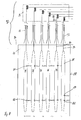
- the top view of Fig. 3 shows in sections one of the trolley 40.
- the trolley 40 is provided with a support rail 50 which forms a continuous top of the trolley 40 and on which the pallets can rest.
- the support rail 50 is tapered at its two ends to allow threading of the trolley 40 in the passage openings 18 of a pallet, even with minor positional deviations. From the in Fig. 3 left end of the trolley 40 goes out of the electrical supply cable 46.
- the support rail 50 has the shape of an inverted U-profile, which opens in the direction of a road surface 52.
- a base of the U-profile thus forms the top of the support rail 50, the mutual legs form laterally from the top down-projecting aprons.
- the side skirts are cut off.
- the trolley 40 is provided with a total of eight support rollers 52, which are interconnected by means of a chassis 54 shown only schematically and rotatably mounted on this. In the presentation of the Fig. 4 only four of the eight idlers are visible.
- the support rollers 52 of the trolley 40 is also provided with two drive rollers 56, 58.
- the drive rollers 56, 58 are each one in Fig. 4 unrecognizable electric motor coupled.
- a sensor 60 is provided at each end of the trolley 40, which detects a reaching an intended end position in the longitudinal direction and in response to the sensor signal of the sensors 60, then the travel drive of the trolley 40 can be stopped.
- the recognizes in the representation of Fig. 4 Right sensor 60 whether the trolley 40 is already directly in front of a rear loader of a truck or immediately before already parked pallets.
- the lifting drive of the trolley 40 is activated to receive or sell pallets.
- the in the representation of the Fig. 4 Sensor 60 arranged at the left end of transport trolley 40 detects in a similar manner whether trolley 40 is already in the transfer station and whether the traction drive should be switched off, switched on or the lifting drive should be activated.
- the trolley 40 is provided with two laterally arranged sensors S1 and S2.
- the sensor S1 detects the lateral distance of the trolley 40 to an adjacent dolly, whereas the sensor S2 is provided for detecting a lateral distance to a side boundary, for example, the lateral wall of the structure of a truck.
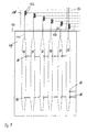
- the presentation of the Fig. 5 shows a view on the cutting plane VV of Fig. 3 , Evident is schematically illustrated chassis 54, on which the transport rollers 52 are rotatably mounted.
- chassis 54 On the chassis 54 two lifting drives 62 and two electric motors 64, 66 are further arranged.
- the electric motor 64 is the in Fig. 5 unrecognizable drive roller 56 associated, whereas the electric motor 66 is coupled to the drive roller 58.
- the electric motors 64, 66 are controlled separately, so that the drive rollers 56, 58 can be driven at different speeds and can also be braked in different ways.
- the lifting drives 62 are each designed as electromechanical drives and, for example, each have an electric motor-driven spindle which moves a spindle nut.
- a push rod 68 is connected, which in turn is pivotally connected to a two-sided lever 70.
- the lever 70 is also hinged to a bracket 72 which is fixedly connected to the chassis 54.
- the push rod 68 opposite end of the lever 70 is pivotally connected to the underside of the support rail 50.
- the right half and the left half of the trolley 40 are constructed approximately mirror-symmetrical to each other and each have a lifting drive 62, a traction drive and four transport rollers 52.
- a single lifting drive or a single drive can be used.
- the presentation of the Fig. 6 shows a view on the section plane VI-VI of the Fig. 4 , It can be seen that the support rollers 52 each as a pair of wheels right and left of a central longitudinal axis 74, the in Fig. 3 is shown, are arranged. The trolley 40 is thereby stable on the road 52. Alternatively, a wide support roller can be used.
- the electric motor 64 drives the drive roller 56, which in the illustration of Fig. 6 is arranged below the central longitudinal axis 74.
- the electric motor 66 drives the drive roller 58, which on the opposite side of the central longitudinal axis 74, in the illustration of Fig. 6 that is arranged above the central longitudinal axis.
- the transport carriage 40 thus moves in a straight line. If the drive rollers 56, 58, however, driven at different speeds or braked at different levels, so some direction corrections in the direction of travel of the trolley 40 can be made.
- Directional corrections are only required to correct for directional deviations, for example due to unforeseen obstacles.
- the two sensors S1, S2 are both arranged on the same side of the trolley 40 and thus only the distance to one in the in the representation of Fig. 6 can detect below lying dolly or to a lower side boundary. However, this is sufficient for detecting the position of a respective trolley, since a plurality of juxtaposed trolley, all ideally move on a linear path, so that the detection the distance is sufficient on only one side to determine the position of the trolley 40.
- the presentation of the Fig. 7 also shows a view of the sectional plane VV of Fig. 3 wherein the trolley 40 in Fig. 7 but is shown in the lowered state.
- the transport carriage 40 In this lowered state, the transport carriage 40 is so low over its entire length that it can enter into the passage openings of a pallet 18 and can traverse it completely.
- the two linear actuators 62 are activated and operated synchronously, by a distance between the top of the support rail 50 and the chassis 54, so a distance between the roadway 52 and the top of the support rail 50th to increase or decrease while keeping the top of the support rail 50 parallel to the roadway 52.
- FIG. 8 schematically shows a plan view of an inventive transport system according to another embodiment.
- a loading ramp is shown schematically only by its front edge 74, wherein immediately before the front edge 74 schematically the loading area 74 of a truck is shown.
- the loading area 44 is located exactly at the same height as the loading ramp and between the front edge of the front edge 74 of the loading ramp and the beginning of the loading area 44 is only a small gap easily to be crossed by the transport trolleys 76 or 78.
- the trolleys 76 are shown on the loading surface 44 and each have two sensors 80, 82 which detect the distance to the respective adjacent trolley 76 and 78, respectively.
- the sensors 80, 82 are arranged in the transport carriage 76 so that both sensors 80, 82 detect the distance to the same side, in the representation of Fig. 8 the distance to each lying on the right side Dolly 76 and 78.
- the in the representation of Fig. 8 rightmost trolley 78 has two sensors 84, 86, both sensors 84, 86 detect the distance to a side wall 88 of the truck. Since the two sensors 84, 86 of the transport carriage 78 are arranged one behind the other as seen in the transport direction, the parallelism of the transport carriage 78 to the side wall 88 can also be detected.
- the sensor 84 on the trolley 78 may, for example, also be more widely spaced than in FIG Fig.
- trolley 8 shown remote from the sensor 86 to allow a more accurate detection of the parallelism of the trolley 78 to the side wall of the truck 88. Since the other trolleys 76 each detect the distance to the right adjacent trolley 76, 78, in this way the position of all trolleys 76 and 78 can be determined relative to the side wall 88 of the truck.
- guide rails 92 are provided for each transport carriage. These guide rails have an extension in the area of the loading ramp in order to introduce the transport carriages 76, 78 into the guide rails 92 even with slight course deviations.
- the guide rails 92 then run straight from the loading dock to a transfer station, as in Fig. 2 is shown.
- the guide rails 92 are advantageously sunk into the road so that they can easily overflow in the transverse direction or can be run over by forklifts.
- the guide rails 92 are suitably matched to the size and position of the trolley 76, 78.
- Each trolley 76, 78 is provided with an electrical supply line 94, which is automatically tracked and can serve as a traction cable in a movement of the trolley 76, 78 of the loading area 44 in the direction of the transfer station.
- the electrical supply line 94 leads electrical energy and data signals to the trolley 76, 78 and away from them.
- the electrical leads 94 are deflected below the road surface in a region 96 which lies behind or below the transfer station and are then laterally deflected below the road surface in the region 96.
- the area 96, in which the electrical leads 94 are deflected laterally below the roadway surface is exemplified by the embodiment of FIG Fig. 2 Below the transfer stations 32a, 32b or below the turning devices 36.
- a cable sensor 98 is also provided, which detects an extension length of one or all of the electrical leads 94.
- the position of the transport carriages 76, 78 in the longitudinal direction can thus be determined.
- This detection of the position of the transport carriage 76, 78 in the longitudinal direction can be used to turn off the distance sensors 80, 82, 84, 86 after leaving the loading area 44, since the guide of the transport carriage 76, 78 is then taken over by the guide rails 92. In any case, it makes sense to switch off the distance sensors 84, 86 on the trolley 78 after leaving the loading area 44, since the side wall 88 of the truck then ends and the sensors 84, 86 can then no longer deliver meaningful signals.
- FIG. 9 shows a schematic plan view of an inventive transport system according to another embodiment of the invention.
- the transport system of Fig. 9 is very similar to the transport system of Fig. 8 constructed so that only the differences are explained functionally identical components and elements of the transport system are provided with the same reference numerals and will not be explained again.
- a lowered portion 130 In contrast to the transport system of Fig. 8 is a lowered portion 130, are arranged in the pulleys 132 for electrical cable leads 134 of the trolley 76, 78, immediately adjacent to arranged the loading edge 74 of a loading dock in a building. Since the region 130 is lowered with the deflection rollers 132, the electrical leads 134 thus change their pulling direction when passing over the region 130.
- the guide rails 92 are identical to the transport system of Fig. 8 However, they also run above the lowered area 130 with the deflection rollers 132.
- a sensor 136 in the region of the loading edge 74 and thus at an edge of the area 130 which faces this loading edge 74 detects the passing of one or all transport vehicles 76, 78 and either turns on the sensors 80, 82, 84, 86 when the trolleys 76, 78 are on their way onto the bed 44, or disables the sensors 80, 82, 84, 86 when the trolleys 76, 78 down from the bed 44 and into the guide rails 92 in move.
- the transport system of Fig. 9 is structurally advantageous, since usually a power connection for the electrical leads 134 in the area of the building edge, ie thus also in the area of the loading edge 74 is available. Since the electrical leads 134 are deflected in the area 130 and this area 130 is located in the vicinity of a building edge, their electrical connection is facilitated since, in contrast to the transport system of the Fig. 8 no electrical connection must be laid to the transfer point.
- FIG. 10 shows a trolley 138 according to the invention in a schematic view from below. Shown are only two transport rollers 140 and a telescopic rail unit 142 which is arranged in the trolley 138.
- the telescopic rail unit 142 can be pulled out and thereby guide the trolley 138 and thus hold on a designated track.
- the telescopic rail unit 142 for example, a extendable engagement hooks 144 which automatically extends when passing over a gap 146 between a loading area 148 of a commercial vehicle to be loaded and a loading dock 150 and hooks into the gap 146.
- the telescoping rail unit 142 Upon return of the trolley 138 to the gap 146, the telescoping rail unit 142 automatically retracts until it returns to the position shown in FIG Fig. 10 shown fully retracted position occupies.
- the hook 144 moves in automatically and the transport carriage 138 can continue on the loading ramp 150, being guided on the loading ramp 150, for example by guide rails.
- FIG. 12 shows a schematic side view of another embodiment of the transport system according to the invention.
- a loading dock 100 in front of a truck is arranged, the truck is aligned with the rear to the loading dock 100 out.
- a chassis 106 of the truck is provided with sliding shoes 108 , which are pushed on a rising slide 110 to a stop 112 along.
- the loading surface 102 is brought exactly to the same height with the road surface 104 and the stop 112 ensures that the end of the loading surface is placed substantially directly on the front edge of the loading dock 100. Since the shoes 108 are fixed to the chassis 106, the loading surface 102 during loading can not down Dodge, since there is a substantially rigid connection between the slide rail 110 and the loading surface 102.
- an eyelet 114 is secured to the chassis 106, which engages in a building-fixed jaw clutch 116.
- an automated loading or unloading operation may only be started when the eyelet 114 is locked in the dog clutch 116.
- the loading surface 102 is thus fixed during the loading process both in the height direction and in the horizontal direction relative to the road surface 104 of the loading dock 100.
- the trolleys 118 can thus receive pallets 14 from a transfer station, transport beyond the front edge of the loading ramp 100 onto the loading area 102 and park there.
- the eyelet 114 and the dog clutch 116 and the sliding shoes 108 and the slide rail 110 are merely an example of possible means for fixing the loading surface 102 in the vertical direction and in the longitudinal direction relative to the loading ramp 100.
- the loading area 102 and the truck itself need not be modified in order to be automatically loaded or unloaded with the transport system according to the invention.
- the trolley 120 has two hinges 120, so that the trolley 118 is divided into three equal-length sections, each having the length of a pallet.
- the joints 120 allow a pivotal movement of the sections to each other, for example, the in Fig. 9 left portion relative to the central portion of the trolley 118 about a pivot axis which is parallel to the road surface 104 and perpendicular to a longitudinal axis of the trolley 118. In the presentation of the Fig. 9 stand the swivel axes thus perpendicular to the drawing plane.
- the hinges 120 are arranged so that each left and right of each hinge 120 each have a pallet on the trolley 118 can be arranged.
- the pivots 120 additionally allow a pivoting movement of the individual sections about an axis of rotation arranged perpendicular to the roadway surface 104.
Landscapes
- Engineering & Computer Science (AREA)
- Aviation & Aerospace Engineering (AREA)
- Mechanical Engineering (AREA)
- Intermediate Stations On Conveyors (AREA)
- Loading Or Unloading Of Vehicles (AREA)
- Platform Screen Doors And Railroad Systems (AREA)
Priority Applications (1)
| Application Number | Priority Date | Filing Date | Title |
|---|---|---|---|
| PL09002978T PL2100831T3 (pl) | 2008-03-12 | 2009-03-03 | Wózek transportowy dla palet i system transportowy |
Applications Claiming Priority (1)
| Application Number | Priority Date | Filing Date | Title |
|---|---|---|---|
| DE102008014877A DE102008014877A1 (de) | 2008-03-12 | 2008-03-12 | Transportwagen für Paletten und Transportsystem |
Publications (3)
| Publication Number | Publication Date |
|---|---|
| EP2100831A1 true EP2100831A1 (fr) | 2009-09-16 |
| EP2100831B1 EP2100831B1 (fr) | 2017-05-03 |
| EP2100831B8 EP2100831B8 (fr) | 2017-07-26 |
Family
ID=40640384
Family Applications (1)
| Application Number | Title | Priority Date | Filing Date |
|---|---|---|---|
| EP09002978.6A Active EP2100831B8 (fr) | 2008-03-12 | 2009-03-03 | Véhicule de transport pour palettes et système de transport |
Country Status (5)
| Country | Link |
|---|---|
| EP (1) | EP2100831B8 (fr) |
| DE (1) | DE102008014877A1 (fr) |
| DK (1) | DK2100831T3 (fr) |
| ES (1) | ES2634652T3 (fr) |
| PL (1) | PL2100831T3 (fr) |
Cited By (14)
| Publication number | Priority date | Publication date | Assignee | Title |
|---|---|---|---|---|
| CN103086164A (zh) * | 2011-10-31 | 2013-05-08 | 三井住友建設株式会社 | 货物装载卸下装置及使用该装置的货物装载卸下方法 |
| EP2765101A1 (fr) * | 2013-02-08 | 2014-08-13 | Alfred Arnold eingetragener Kaufmann Verladesysteme | Chariot de transport automoteur pour palettes |
| EP2765100A1 (fr) | 2013-02-08 | 2014-08-13 | Alfred Arnold eingetragener Kaufmann Verladesysteme | Système de transport et chariot de transport pour palettes |
| WO2015055306A1 (fr) * | 2013-10-15 | 2015-04-23 | Eisenmann Se | Unité de transport et système de transport permettant de transporter des supports de charge |
| EP3020614A1 (fr) * | 2014-11-17 | 2016-05-18 | Eisenmann SE | Systeme de convoyage d'objets et son procede de commande |
| WO2016082917A1 (fr) * | 2014-11-24 | 2016-06-02 | /1Eisenmann Se | Unité de transport et système de transport servant à transporter des supports de charge |
| EP3036179A1 (fr) * | 2013-08-23 | 2016-06-29 | Eisenmann SE | Procédé et installation permettant de transporter des supports de charge |
| EP3266673A1 (fr) * | 2016-07-06 | 2018-01-10 | Hyster-Yale Group, Inc. | Manipulation de charge automatisée pour véhicule industriel |
| USD819852S1 (en) | 2016-07-18 | 2018-06-05 | Hyster-Yale Group, Inc. | Lighting for a pallet truck |
| CN108609410A (zh) * | 2018-05-20 | 2018-10-02 | 成都鸿源锦程机器人有限公司 | 一种拨臂式自动装车机器人 |
| US10233064B2 (en) | 2016-07-06 | 2019-03-19 | Hyster-Yale Group, Inc. | Automated load handling for industrial vehicle |
| CN110155750A (zh) * | 2019-07-03 | 2019-08-23 | 无锡宏盛智能装载技术有限公司 | 有托盘货物自动装卸车机 |
| CN110244706A (zh) * | 2019-05-09 | 2019-09-17 | 盐城品迅智能科技服务有限公司 | 一种自主识别高度并具有顶升功能的智能搬运车及搬运方法 |
| RU2739309C1 (ru) * | 2019-12-30 | 2020-12-22 | Акционерное общество "Полюс Красноярск" | Устройство для замены бронефутеровочных плит |
Families Citing this family (8)
| Publication number | Priority date | Publication date | Assignee | Title |
|---|---|---|---|---|
| DE102013202093A1 (de) | 2013-02-08 | 2014-08-28 | Alfred Arnold Eingetragener Kaufmann Verladesysteme | Transportwagen für Paletten |
| DE102013013684A1 (de) * | 2013-08-16 | 2015-02-19 | Eisenmann Ag | Fördereinheit und Fördersystem mit solchen Fördereinheiten |
| DE102014017254A1 (de) | 2014-11-24 | 2016-05-25 | Eisenmann Se | Fördereinheit und Fördersystem zum Fördern von Ladungsträgern |
| EP3216747A1 (fr) | 2016-03-07 | 2017-09-13 | Melkus Mechatronic GmbH | Véhicule de transport sans conducteur |
| DE102017215366A1 (de) | 2017-09-01 | 2019-03-07 | Koenig & Bauer Ag | Bogenrotationsdruckmaschine |
| DE102019001125B4 (de) | 2019-02-15 | 2022-01-20 | FILICS GmbH | Fördereinrichtung für Ladungsträger mit integrierter Kollisionsdetektion |
| DE102019001455A1 (de) * | 2019-03-01 | 2020-09-03 | FILICS GmbH | Fördersystem zum Fördern von Ladungsträgern, sowie deren Steuerungsverfahren |
| EP4269321A3 (fr) | 2019-02-15 | 2023-12-20 | Filics GmbH | Dispositif de transport pour porteurs de charge |
Citations (8)
| Publication number | Priority date | Publication date | Assignee | Title |
|---|---|---|---|---|
| US3973685A (en) * | 1973-12-17 | 1976-08-10 | Litton Systems, Inc. | Photoelectric sensing apparatus for pallet storage systems |
| DE2706986A1 (de) * | 1977-02-18 | 1978-08-24 | Miebach Ges Fuer Ind Und Mater | Ladevorrichtung fuer ein transportgeraet |
| DE3244198A1 (de) * | 1982-11-30 | 1984-05-30 | Heinrich 6200 Wiesbaden Kromer | Plattform fuer palettentransport |
| EP0198738A1 (fr) | 1985-04-10 | 1986-10-22 | Gérard Luneau | Procédé et installation de manutention et de transfert de charges palettisées ou containerisées, notamment en vue du chargement et du déchargement de véhicules |
| US5374151A (en) * | 1990-07-14 | 1994-12-20 | Matthews; Robin | Transport loading system |
| JPH11130268A (ja) * | 1997-10-28 | 1999-05-18 | Takeshi Hayashi | フォーク移動式荷役装置及び荷役方法 |
| US20040197172A1 (en) * | 2001-07-04 | 2004-10-07 | Rudolf Hansl | Transfer car for loading and unloading transported goods |
| EP1967484A1 (fr) * | 2007-03-05 | 2008-09-10 | Yvon Le Roy | Dispositif de manutention motorisée horizontale et collective de palettes pour charger ou décharger les véhicules |
Family Cites Families (8)
| Publication number | Priority date | Publication date | Assignee | Title |
|---|---|---|---|---|
| DE2747250C3 (de) * | 1977-10-21 | 1980-05-08 | Mannesmann Ag, 4000 Duesseldorf | Einrichtung zum Umsetzen von Stückgut, insbesondere bei Ladeflächen von Lastkraftwagen |
| FR2592865B1 (fr) * | 1986-01-14 | 1991-03-29 | Unisabi Sa | Dispositif de transfert de chargement, en particulier pour le transfert rapide de charges palettisees |
| DE9402749U1 (de) * | 1994-02-21 | 1994-06-30 | Schier GmbH & Co. KG, 33161 Hövelhof | Verladeanlage zum Be- und Entladen von Nutzfahrzeugen und/oder Rampen |
| DE19629409A1 (de) * | 1996-07-22 | 1998-01-29 | Reinhard Reiter | Paletten - Transportsystem |
| DE29922540U1 (de) * | 1999-12-22 | 2001-05-03 | AUTEFA Automation GmbH, 86316 Friedberg | Beladevorrichtung für Transportfahrzeuge |
| DE20220794U1 (de) * | 2002-11-22 | 2004-05-13 | Alstom Power Boiler Gmbh | Zirkulierender Wirbelschichtreaktor |
| DE102005038511B3 (de) * | 2005-07-29 | 2007-02-15 | Alfred Arnold Verladesysteme | Blockiervorrichtung für ein Nutzfahrzeug |
| DE102007046868B9 (de) * | 2007-09-28 | 2023-08-31 | Universität Stuttgart | Transportvorrichtung für Ladungsträger und Verfahren zu deren Steuerung |
-
2008
- 2008-03-12 DE DE102008014877A patent/DE102008014877A1/de not_active Ceased
-
2009
- 2009-03-03 ES ES09002978.6T patent/ES2634652T3/es active Active
- 2009-03-03 PL PL09002978T patent/PL2100831T3/pl unknown
- 2009-03-03 EP EP09002978.6A patent/EP2100831B8/fr active Active
- 2009-03-03 DK DK09002978.6T patent/DK2100831T3/en active
Patent Citations (8)
| Publication number | Priority date | Publication date | Assignee | Title |
|---|---|---|---|---|
| US3973685A (en) * | 1973-12-17 | 1976-08-10 | Litton Systems, Inc. | Photoelectric sensing apparatus for pallet storage systems |
| DE2706986A1 (de) * | 1977-02-18 | 1978-08-24 | Miebach Ges Fuer Ind Und Mater | Ladevorrichtung fuer ein transportgeraet |
| DE3244198A1 (de) * | 1982-11-30 | 1984-05-30 | Heinrich 6200 Wiesbaden Kromer | Plattform fuer palettentransport |
| EP0198738A1 (fr) | 1985-04-10 | 1986-10-22 | Gérard Luneau | Procédé et installation de manutention et de transfert de charges palettisées ou containerisées, notamment en vue du chargement et du déchargement de véhicules |
| US5374151A (en) * | 1990-07-14 | 1994-12-20 | Matthews; Robin | Transport loading system |
| JPH11130268A (ja) * | 1997-10-28 | 1999-05-18 | Takeshi Hayashi | フォーク移動式荷役装置及び荷役方法 |
| US20040197172A1 (en) * | 2001-07-04 | 2004-10-07 | Rudolf Hansl | Transfer car for loading and unloading transported goods |
| EP1967484A1 (fr) * | 2007-03-05 | 2008-09-10 | Yvon Le Roy | Dispositif de manutention motorisée horizontale et collective de palettes pour charger ou décharger les véhicules |
Cited By (21)
| Publication number | Priority date | Publication date | Assignee | Title |
|---|---|---|---|---|
| CN103086164B (zh) * | 2011-10-31 | 2016-05-18 | 三井住友建設株式会社 | 货物装载卸下装置及使用该装置的货物装载卸下方法 |
| CN103086164A (zh) * | 2011-10-31 | 2013-05-08 | 三井住友建設株式会社 | 货物装载卸下装置及使用该装置的货物装载卸下方法 |
| EP2765101A1 (fr) * | 2013-02-08 | 2014-08-13 | Alfred Arnold eingetragener Kaufmann Verladesysteme | Chariot de transport automoteur pour palettes |
| EP2765100A1 (fr) | 2013-02-08 | 2014-08-13 | Alfred Arnold eingetragener Kaufmann Verladesysteme | Système de transport et chariot de transport pour palettes |
| DE102013202074A1 (de) | 2013-02-08 | 2014-08-14 | Alfred Arnold Eingetragener Kaufmann Verladesysteme | Transportsystem und Transportwagen für Paletten |
| EP3036179A1 (fr) * | 2013-08-23 | 2016-06-29 | Eisenmann SE | Procédé et installation permettant de transporter des supports de charge |
| EP3057845B1 (fr) | 2013-10-15 | 2021-03-03 | pentanova cs GmbH | Unité de transport et système de transport permettant de transporter des supports de charge |
| WO2015055306A1 (fr) * | 2013-10-15 | 2015-04-23 | Eisenmann Se | Unité de transport et système de transport permettant de transporter des supports de charge |
| EP3020614A1 (fr) * | 2014-11-17 | 2016-05-18 | Eisenmann SE | Systeme de convoyage d'objets et son procede de commande |
| US9709977B2 (en) | 2014-11-17 | 2017-07-18 | Eisenmann Se | Conveyor system for conveying objects and control process for such a system |
| WO2016082917A1 (fr) * | 2014-11-24 | 2016-06-02 | /1Eisenmann Se | Unité de transport et système de transport servant à transporter des supports de charge |
| EP3266673A1 (fr) * | 2016-07-06 | 2018-01-10 | Hyster-Yale Group, Inc. | Manipulation de charge automatisée pour véhicule industriel |
| US10233064B2 (en) | 2016-07-06 | 2019-03-19 | Hyster-Yale Group, Inc. | Automated load handling for industrial vehicle |
| USD819853S1 (en) | 2016-07-18 | 2018-06-05 | Hyster-Yale Group, Inc. | Lighting for a pallet truck |
| USD819852S1 (en) | 2016-07-18 | 2018-06-05 | Hyster-Yale Group, Inc. | Lighting for a pallet truck |
| CN108609410A (zh) * | 2018-05-20 | 2018-10-02 | 成都鸿源锦程机器人有限公司 | 一种拨臂式自动装车机器人 |
| CN108609410B (zh) * | 2018-05-20 | 2024-01-26 | 成都鸿源锦程机器人有限公司 | 一种拨臂式自动装车机器人 |
| CN110244706A (zh) * | 2019-05-09 | 2019-09-17 | 盐城品迅智能科技服务有限公司 | 一种自主识别高度并具有顶升功能的智能搬运车及搬运方法 |
| CN110155750A (zh) * | 2019-07-03 | 2019-08-23 | 无锡宏盛智能装载技术有限公司 | 有托盘货物自动装卸车机 |
| CN110155750B (zh) * | 2019-07-03 | 2023-12-01 | 无锡宏盛智能装载技术有限公司 | 有托盘货物自动装卸车机 |
| RU2739309C1 (ru) * | 2019-12-30 | 2020-12-22 | Акционерное общество "Полюс Красноярск" | Устройство для замены бронефутеровочных плит |
Also Published As
| Publication number | Publication date |
|---|---|
| EP2100831B1 (fr) | 2017-05-03 |
| EP2100831B8 (fr) | 2017-07-26 |
| PL2100831T3 (pl) | 2017-10-31 |
| ES2634652T3 (es) | 2017-09-28 |
| DE102008014877A1 (de) | 2009-11-05 |
| DK2100831T3 (en) | 2017-08-28 |
Similar Documents
| Publication | Publication Date | Title |
|---|---|---|
| EP2100831B1 (fr) | Véhicule de transport pour palettes et système de transport | |
| EP3456663B1 (fr) | Dispositif de transport de palettes | |
| EP2487067B1 (fr) | Chariot industriel et train formé par de tels chariots | |
| EP2794430B1 (fr) | Système d'emmagasinage à rayonnages et son procédé de fonctionnement | |
| EP2607292B1 (fr) | Système de transport des marchandises disposées sur les aides auxiliaires | |
| EP2614198B1 (fr) | Dispositif et procédé permettant le parcage transversal automatique d'un véhicule à moteur dans un parking | |
| EP2885199B1 (fr) | Remorque de train de remorques | |
| EP1808387B1 (fr) | Système logistique | |
| EP3243769B1 (fr) | Procédé et dispositif de stockage de marchandises au détail à l'aide de rangées d'étagères pouvant être reliées | |
| DE202009016799U1 (de) | Logistiksystem | |
| DE102006000654B4 (de) | Verfahren und Anordnung zum Wenden von Paletten | |
| EP1988053A2 (fr) | Convoyeurs au sol pour transporter des transconteneurs | |
| DE102004018910A1 (de) | Flurfolgefahrzeug | |
| DE102009026701A1 (de) | Verfahren zum gleichzeitigen Beladen einer Ladefläche eines Lastfahrzeugs mit einer Vielzahl von Güterpaletten und Lademaschine dafür | |
| EP3345786A1 (fr) | Train de remorque pour dispositif de roulage au sol | |
| EP3686053B1 (fr) | Véhicule de levage, de transport et d'abaissement des porteurs de charge | |
| DE2811797A1 (de) | Vorrichtung zum verladen von guetern | |
| DE3640770C2 (de) | Transportwagen | |
| DE102017101368A1 (de) | Routenzuganhänger für Bodenroller | |
| EP2765100B1 (fr) | Système de transport et chariot de transport pour palettes | |
| EP1357061A2 (fr) | Chariot de transport pour rayonnage d'entrepôt et vehicule d'entrepôt avec un tel chariot | |
| DE102022132923B4 (de) | Logistiksystem | |
| DE2920099C2 (de) | Verfahren und Vorrichtung zum Lenken eines Flurförderers | |
| EP2518005A1 (fr) | Chariot de manutention | |
| DE2159488A1 (de) | Transport von versandguetern |
Legal Events
| Date | Code | Title | Description |
|---|---|---|---|
| PUAI | Public reference made under article 153(3) epc to a published international application that has entered the european phase |
Free format text: ORIGINAL CODE: 0009012 |
|
| AK | Designated contracting states |
Kind code of ref document: A1 Designated state(s): AT BE BG CH CY CZ DE DK EE ES FI FR GB GR HR HU IE IS IT LI LT LU LV MC MK MT NL NO PL PT RO SE SI SK TR |
|
| AX | Request for extension of the european patent |
Extension state: AL BA RS |
|
| 17P | Request for examination filed |
Effective date: 20100305 |
|
| AKX | Designation fees paid |
Designated state(s): AT BE BG CH CY CZ DE DK EE ES FI FR GB GR HR HU IE IS IT LI LT LU LV MC MK MT NL NO PL PT RO SE SI SK TR |
|
| 17Q | First examination report despatched |
Effective date: 20100602 |
|
| GRAP | Despatch of communication of intention to grant a patent |
Free format text: ORIGINAL CODE: EPIDOSNIGR1 |
|
| INTG | Intention to grant announced |
Effective date: 20161010 |
|
| GRAS | Grant fee paid |
Free format text: ORIGINAL CODE: EPIDOSNIGR3 |
|
| GRAA | (expected) grant |
Free format text: ORIGINAL CODE: 0009210 |
|
| AK | Designated contracting states |
Kind code of ref document: B1 Designated state(s): AT BE BG CH CY CZ DE DK EE ES FI FR GB GR HR HU IE IS IT LI LT LU LV MC MK MT NL NO PL PT RO SE SI SK TR |
|
| REG | Reference to a national code |
Ref country code: GB Ref legal event code: FG4D Free format text: NOT ENGLISH |
|
| REG | Reference to a national code |
Ref country code: AT Ref legal event code: REF Ref document number: 889714 Country of ref document: AT Kind code of ref document: T Effective date: 20170515 Ref country code: CH Ref legal event code: EP |
|
| REG | Reference to a national code |
Ref country code: IE Ref legal event code: FG4D Free format text: LANGUAGE OF EP DOCUMENT: GERMAN |
|
| REG | Reference to a national code |
Ref country code: DE Ref legal event code: R096 Ref document number: 502009013927 Country of ref document: DE |
|
| RAP2 | Party data changed (patent owner data changed or rights of a patent transferred) |
Owner name: ALFRED ARNOLD EINGETRAGENER KAUFMANN VERLADESYSTEM |
|
| REG | Reference to a national code |
Ref country code: CH Ref legal event code: NV Representative=s name: DR. LUSUARDI AG, CH |
|
| REG | Reference to a national code |
Ref country code: SE Ref legal event code: TRGR |
|
| REG | Reference to a national code |
Ref country code: NL Ref legal event code: FP |
|
| REG | Reference to a national code |
Ref country code: DK Ref legal event code: T3 Effective date: 20170822 |
|
| REG | Reference to a national code |
Ref country code: LT Ref legal event code: MG4D |
|
| REG | Reference to a national code |
Ref country code: ES Ref legal event code: FG2A Ref document number: 2634652 Country of ref document: ES Kind code of ref document: T3 Effective date: 20170928 |
|
| PG25 | Lapsed in a contracting state [announced via postgrant information from national office to epo] |
Ref country code: FI Free format text: LAPSE BECAUSE OF FAILURE TO SUBMIT A TRANSLATION OF THE DESCRIPTION OR TO PAY THE FEE WITHIN THE PRESCRIBED TIME-LIMIT Effective date: 20170503 Ref country code: GR Free format text: LAPSE BECAUSE OF FAILURE TO SUBMIT A TRANSLATION OF THE DESCRIPTION OR TO PAY THE FEE WITHIN THE PRESCRIBED TIME-LIMIT Effective date: 20170804 Ref country code: HR Free format text: LAPSE BECAUSE OF FAILURE TO SUBMIT A TRANSLATION OF THE DESCRIPTION OR TO PAY THE FEE WITHIN THE PRESCRIBED TIME-LIMIT Effective date: 20170503 Ref country code: NO Free format text: LAPSE BECAUSE OF FAILURE TO SUBMIT A TRANSLATION OF THE DESCRIPTION OR TO PAY THE FEE WITHIN THE PRESCRIBED TIME-LIMIT Effective date: 20170803 Ref country code: LT Free format text: LAPSE BECAUSE OF FAILURE TO SUBMIT A TRANSLATION OF THE DESCRIPTION OR TO PAY THE FEE WITHIN THE PRESCRIBED TIME-LIMIT Effective date: 20170503 |
|
| PG25 | Lapsed in a contracting state [announced via postgrant information from national office to epo] |
Ref country code: BG Free format text: LAPSE BECAUSE OF FAILURE TO SUBMIT A TRANSLATION OF THE DESCRIPTION OR TO PAY THE FEE WITHIN THE PRESCRIBED TIME-LIMIT Effective date: 20170803 Ref country code: IS Free format text: LAPSE BECAUSE OF FAILURE TO SUBMIT A TRANSLATION OF THE DESCRIPTION OR TO PAY THE FEE WITHIN THE PRESCRIBED TIME-LIMIT Effective date: 20170903 Ref country code: LV Free format text: LAPSE BECAUSE OF FAILURE TO SUBMIT A TRANSLATION OF THE DESCRIPTION OR TO PAY THE FEE WITHIN THE PRESCRIBED TIME-LIMIT Effective date: 20170503 |
|
| PG25 | Lapsed in a contracting state [announced via postgrant information from national office to epo] |
Ref country code: SK Free format text: LAPSE BECAUSE OF FAILURE TO SUBMIT A TRANSLATION OF THE DESCRIPTION OR TO PAY THE FEE WITHIN THE PRESCRIBED TIME-LIMIT Effective date: 20170503 Ref country code: CZ Free format text: LAPSE BECAUSE OF FAILURE TO SUBMIT A TRANSLATION OF THE DESCRIPTION OR TO PAY THE FEE WITHIN THE PRESCRIBED TIME-LIMIT Effective date: 20170503 Ref country code: EE Free format text: LAPSE BECAUSE OF FAILURE TO SUBMIT A TRANSLATION OF THE DESCRIPTION OR TO PAY THE FEE WITHIN THE PRESCRIBED TIME-LIMIT Effective date: 20170503 Ref country code: RO Free format text: LAPSE BECAUSE OF FAILURE TO SUBMIT A TRANSLATION OF THE DESCRIPTION OR TO PAY THE FEE WITHIN THE PRESCRIBED TIME-LIMIT Effective date: 20170503 |
|
| REG | Reference to a national code |
Ref country code: DE Ref legal event code: R097 Ref document number: 502009013927 Country of ref document: DE |
|
| PG25 | Lapsed in a contracting state [announced via postgrant information from national office to epo] |
Ref country code: IT Free format text: LAPSE BECAUSE OF FAILURE TO SUBMIT A TRANSLATION OF THE DESCRIPTION OR TO PAY THE FEE WITHIN THE PRESCRIBED TIME-LIMIT Effective date: 20170503 |
|
| PLBE | No opposition filed within time limit |
Free format text: ORIGINAL CODE: 0009261 |
|
| STAA | Information on the status of an ep patent application or granted ep patent |
Free format text: STATUS: NO OPPOSITION FILED WITHIN TIME LIMIT |
|
| REG | Reference to a national code |
Ref country code: FR Ref legal event code: PLFP Year of fee payment: 10 |
|
| 26N | No opposition filed |
Effective date: 20180206 |
|
| PG25 | Lapsed in a contracting state [announced via postgrant information from national office to epo] |
Ref country code: SI Free format text: LAPSE BECAUSE OF FAILURE TO SUBMIT A TRANSLATION OF THE DESCRIPTION OR TO PAY THE FEE WITHIN THE PRESCRIBED TIME-LIMIT Effective date: 20170503 |
|
| PG25 | Lapsed in a contracting state [announced via postgrant information from national office to epo] |
Ref country code: MT Free format text: LAPSE BECAUSE OF FAILURE TO SUBMIT A TRANSLATION OF THE DESCRIPTION OR TO PAY THE FEE WITHIN THE PRESCRIBED TIME-LIMIT Effective date: 20170503 |
|
| PG25 | Lapsed in a contracting state [announced via postgrant information from national office to epo] |
Ref country code: MC Free format text: LAPSE BECAUSE OF FAILURE TO SUBMIT A TRANSLATION OF THE DESCRIPTION OR TO PAY THE FEE WITHIN THE PRESCRIBED TIME-LIMIT Effective date: 20170503 |
|
| REG | Reference to a national code |
Ref country code: IE Ref legal event code: MM4A |
|
| PG25 | Lapsed in a contracting state [announced via postgrant information from national office to epo] |
Ref country code: LU Free format text: LAPSE BECAUSE OF NON-PAYMENT OF DUE FEES Effective date: 20180303 |
|
| PG25 | Lapsed in a contracting state [announced via postgrant information from national office to epo] |
Ref country code: IE Free format text: LAPSE BECAUSE OF NON-PAYMENT OF DUE FEES Effective date: 20180303 |
|
| PG25 | Lapsed in a contracting state [announced via postgrant information from national office to epo] |
Ref country code: TR Free format text: LAPSE BECAUSE OF FAILURE TO SUBMIT A TRANSLATION OF THE DESCRIPTION OR TO PAY THE FEE WITHIN THE PRESCRIBED TIME-LIMIT Effective date: 20170503 |
|
| PGFP | Annual fee paid to national office [announced via postgrant information from national office to epo] |
Ref country code: PL Payment date: 20200207 Year of fee payment: 12 Ref country code: SE Payment date: 20200325 Year of fee payment: 12 Ref country code: NL Payment date: 20200323 Year of fee payment: 12 Ref country code: GB Payment date: 20200325 Year of fee payment: 12 Ref country code: AT Payment date: 20200319 Year of fee payment: 12 Ref country code: DK Payment date: 20200323 Year of fee payment: 12 |
|
| PG25 | Lapsed in a contracting state [announced via postgrant information from national office to epo] |
Ref country code: HU Free format text: LAPSE BECAUSE OF FAILURE TO SUBMIT A TRANSLATION OF THE DESCRIPTION OR TO PAY THE FEE WITHIN THE PRESCRIBED TIME-LIMIT; INVALID AB INITIO Effective date: 20090303 Ref country code: PT Free format text: LAPSE BECAUSE OF FAILURE TO SUBMIT A TRANSLATION OF THE DESCRIPTION OR TO PAY THE FEE WITHIN THE PRESCRIBED TIME-LIMIT Effective date: 20170503 |
|
| PGFP | Annual fee paid to national office [announced via postgrant information from national office to epo] |
Ref country code: BE Payment date: 20200323 Year of fee payment: 12 |
|
| PG25 | Lapsed in a contracting state [announced via postgrant information from national office to epo] |
Ref country code: MK Free format text: LAPSE BECAUSE OF NON-PAYMENT OF DUE FEES Effective date: 20170503 Ref country code: CY Free format text: LAPSE BECAUSE OF FAILURE TO SUBMIT A TRANSLATION OF THE DESCRIPTION OR TO PAY THE FEE WITHIN THE PRESCRIBED TIME-LIMIT Effective date: 20170503 |
|
| PGFP | Annual fee paid to national office [announced via postgrant information from national office to epo] |
Ref country code: ES Payment date: 20200421 Year of fee payment: 12 |
|
| PGFP | Annual fee paid to national office [announced via postgrant information from national office to epo] |
Ref country code: CH Payment date: 20210324 Year of fee payment: 13 |
|
| REG | Reference to a national code |
Ref country code: DK Ref legal event code: EBP Effective date: 20210331 |
|
| REG | Reference to a national code |
Ref country code: NL Ref legal event code: MM Effective date: 20210401 |
|
| REG | Reference to a national code |
Ref country code: AT Ref legal event code: MM01 Ref document number: 889714 Country of ref document: AT Kind code of ref document: T Effective date: 20210303 |
|
| GBPC | Gb: european patent ceased through non-payment of renewal fee |
Effective date: 20210303 |
|
| REG | Reference to a national code |
Ref country code: BE Ref legal event code: MM Effective date: 20210331 |
|
| PG25 | Lapsed in a contracting state [announced via postgrant information from national office to epo] |
Ref country code: AT Free format text: LAPSE BECAUSE OF NON-PAYMENT OF DUE FEES Effective date: 20210303 Ref country code: NL Free format text: LAPSE BECAUSE OF NON-PAYMENT OF DUE FEES Effective date: 20210401 Ref country code: SE Free format text: LAPSE BECAUSE OF NON-PAYMENT OF DUE FEES Effective date: 20210304 Ref country code: GB Free format text: LAPSE BECAUSE OF NON-PAYMENT OF DUE FEES Effective date: 20210303 |
|
| PG25 | Lapsed in a contracting state [announced via postgrant information from national office to epo] |
Ref country code: DK Free format text: LAPSE BECAUSE OF NON-PAYMENT OF DUE FEES Effective date: 20210331 |
|
| REG | Reference to a national code |
Ref country code: ES Ref legal event code: FD2A Effective date: 20220517 |
|
| PGFP | Annual fee paid to national office [announced via postgrant information from national office to epo] |
Ref country code: FR Payment date: 20220322 Year of fee payment: 14 |
|
| PG25 | Lapsed in a contracting state [announced via postgrant information from national office to epo] |
Ref country code: ES Free format text: LAPSE BECAUSE OF NON-PAYMENT OF DUE FEES Effective date: 20210304 Ref country code: BE Free format text: LAPSE BECAUSE OF NON-PAYMENT OF DUE FEES Effective date: 20210331 |
|
| REG | Reference to a national code |
Ref country code: CH Ref legal event code: PL |
|
| PG25 | Lapsed in a contracting state [announced via postgrant information from national office to epo] |
Ref country code: LI Free format text: LAPSE BECAUSE OF NON-PAYMENT OF DUE FEES Effective date: 20220331 Ref country code: CH Free format text: LAPSE BECAUSE OF NON-PAYMENT OF DUE FEES Effective date: 20220331 |
|
| PG25 | Lapsed in a contracting state [announced via postgrant information from national office to epo] |
Ref country code: PL Free format text: LAPSE BECAUSE OF NON-PAYMENT OF DUE FEES Effective date: 20210303 |
|
| PGFP | Annual fee paid to national office [announced via postgrant information from national office to epo] |
Ref country code: DE Payment date: 20230323 Year of fee payment: 15 |
|
| PG25 | Lapsed in a contracting state [announced via postgrant information from national office to epo] |
Ref country code: FR Free format text: LAPSE BECAUSE OF NON-PAYMENT OF DUE FEES Effective date: 20230331 |