EP2100672A2 - Kombimaschine, insbesondere zum Bemalen von Glas-, Kristall- oder andere, flache Oberflächenplatten - Google Patents
Kombimaschine, insbesondere zum Bemalen von Glas-, Kristall- oder andere, flache Oberflächenplatten Download PDFInfo
- Publication number
- EP2100672A2 EP2100672A2 EP09154977A EP09154977A EP2100672A2 EP 2100672 A2 EP2100672 A2 EP 2100672A2 EP 09154977 A EP09154977 A EP 09154977A EP 09154977 A EP09154977 A EP 09154977A EP 2100672 A2 EP2100672 A2 EP 2100672A2
- Authority
- EP
- European Patent Office
- Prior art keywords
- rollers
- roller
- applicator
- sheet
- paint
- Prior art date
- Legal status (The legal status is an assumption and is not a legal conclusion. Google has not performed a legal analysis and makes no representation as to the accuracy of the status listed.)
- Withdrawn
Links
Images


Classifications
-
- B—PERFORMING OPERATIONS; TRANSPORTING
- B05—SPRAYING OR ATOMISING IN GENERAL; APPLYING FLUENT MATERIALS TO SURFACES, IN GENERAL
- B05C—APPARATUS FOR APPLYING FLUENT MATERIALS TO SURFACES, IN GENERAL
- B05C1/00—Apparatus in which liquid or other fluent material is applied to the surface of the work by contact with a member carrying the liquid or other fluent material, e.g. a porous member loaded with a liquid to be applied as a coating
- B05C1/02—Apparatus in which liquid or other fluent material is applied to the surface of the work by contact with a member carrying the liquid or other fluent material, e.g. a porous member loaded with a liquid to be applied as a coating for applying liquid or other fluent material to separate articles
- B05C1/025—Apparatus in which liquid or other fluent material is applied to the surface of the work by contact with a member carrying the liquid or other fluent material, e.g. a porous member loaded with a liquid to be applied as a coating for applying liquid or other fluent material to separate articles to flat rectangular articles, e.g. flat sheets
-
- B—PERFORMING OPERATIONS; TRANSPORTING
- B05—SPRAYING OR ATOMISING IN GENERAL; APPLYING FLUENT MATERIALS TO SURFACES, IN GENERAL
- B05C—APPARATUS FOR APPLYING FLUENT MATERIALS TO SURFACES, IN GENERAL
- B05C1/00—Apparatus in which liquid or other fluent material is applied to the surface of the work by contact with a member carrying the liquid or other fluent material, e.g. a porous member loaded with a liquid to be applied as a coating
- B05C1/04—Apparatus in which liquid or other fluent material is applied to the surface of the work by contact with a member carrying the liquid or other fluent material, e.g. a porous member loaded with a liquid to be applied as a coating for applying liquid or other fluent material to work of indefinite length
- B05C1/08—Apparatus in which liquid or other fluent material is applied to the surface of the work by contact with a member carrying the liquid or other fluent material, e.g. a porous member loaded with a liquid to be applied as a coating for applying liquid or other fluent material to work of indefinite length using a roller or other rotating member which contacts the work along a generating line
- B05C1/0813—Apparatus in which liquid or other fluent material is applied to the surface of the work by contact with a member carrying the liquid or other fluent material, e.g. a porous member loaded with a liquid to be applied as a coating for applying liquid or other fluent material to work of indefinite length using a roller or other rotating member which contacts the work along a generating line characterised by means for supplying liquid or other fluent material to the roller
-
- B—PERFORMING OPERATIONS; TRANSPORTING
- B05—SPRAYING OR ATOMISING IN GENERAL; APPLYING FLUENT MATERIALS TO SURFACES, IN GENERAL
- B05C—APPARATUS FOR APPLYING FLUENT MATERIALS TO SURFACES, IN GENERAL
- B05C1/00—Apparatus in which liquid or other fluent material is applied to the surface of the work by contact with a member carrying the liquid or other fluent material, e.g. a porous member loaded with a liquid to be applied as a coating
- B05C1/04—Apparatus in which liquid or other fluent material is applied to the surface of the work by contact with a member carrying the liquid or other fluent material, e.g. a porous member loaded with a liquid to be applied as a coating for applying liquid or other fluent material to work of indefinite length
- B05C1/08—Apparatus in which liquid or other fluent material is applied to the surface of the work by contact with a member carrying the liquid or other fluent material, e.g. a porous member loaded with a liquid to be applied as a coating for applying liquid or other fluent material to work of indefinite length using a roller or other rotating member which contacts the work along a generating line
- B05C1/0856—Reverse coating rollers
-
- B—PERFORMING OPERATIONS; TRANSPORTING
- B05—SPRAYING OR ATOMISING IN GENERAL; APPLYING FLUENT MATERIALS TO SURFACES, IN GENERAL
- B05C—APPARATUS FOR APPLYING FLUENT MATERIALS TO SURFACES, IN GENERAL
- B05C1/00—Apparatus in which liquid or other fluent material is applied to the surface of the work by contact with a member carrying the liquid or other fluent material, e.g. a porous member loaded with a liquid to be applied as a coating
- B05C1/04—Apparatus in which liquid or other fluent material is applied to the surface of the work by contact with a member carrying the liquid or other fluent material, e.g. a porous member loaded with a liquid to be applied as a coating for applying liquid or other fluent material to work of indefinite length
- B05C1/08—Apparatus in which liquid or other fluent material is applied to the surface of the work by contact with a member carrying the liquid or other fluent material, e.g. a porous member loaded with a liquid to be applied as a coating for applying liquid or other fluent material to work of indefinite length using a roller or other rotating member which contacts the work along a generating line
- B05C1/086—Apparatus in which liquid or other fluent material is applied to the surface of the work by contact with a member carrying the liquid or other fluent material, e.g. a porous member loaded with a liquid to be applied as a coating for applying liquid or other fluent material to work of indefinite length using a roller or other rotating member which contacts the work along a generating line a pool of coating material being formed between a roller, e.g. a dosing roller and an element cooperating therewith
- B05C1/0865—Apparatus in which liquid or other fluent material is applied to the surface of the work by contact with a member carrying the liquid or other fluent material, e.g. a porous member loaded with a liquid to be applied as a coating for applying liquid or other fluent material to work of indefinite length using a roller or other rotating member which contacts the work along a generating line a pool of coating material being formed between a roller, e.g. a dosing roller and an element cooperating therewith the cooperating element being a roller, e.g. a coating roller
-
- B—PERFORMING OPERATIONS; TRANSPORTING
- B05—SPRAYING OR ATOMISING IN GENERAL; APPLYING FLUENT MATERIALS TO SURFACES, IN GENERAL
- B05C—APPARATUS FOR APPLYING FLUENT MATERIALS TO SURFACES, IN GENERAL
- B05C9/00—Apparatus or plant for applying liquid or other fluent material to surfaces by means not covered by any preceding group, or in which the means of applying the liquid or other fluent material is not important
- B05C9/06—Apparatus or plant for applying liquid or other fluent material to surfaces by means not covered by any preceding group, or in which the means of applying the liquid or other fluent material is not important for applying two different liquids or other fluent materials, or the same liquid or other fluent material twice, to the same side of the work
Definitions
- the invention relates to machines for painting, on an industrial scale, sheets of glass, crystal or other flat surfaces in general. More specifically it relates to roller-type painting machines having at least one rubber-coated roller which engages with inking means and transfers the paint to the sheets which travel continuously on a horizontal conveyor. The continuity of this movement is the reason for the high hourly production rate of these machines.
- the machines also have means operating by a guide and slide or an eccentric to adjust the distance between the metering roller and the applicator roller and thereby vary the amount of paint transferred onto the latter roller and thence to the advancing glass sheet.
- the applicator roller rotates in the same direction of advance as the glass sheet which advances on a belt conveyor or motorized rollers, with no relative movement occurring between the sheet and the applicator roller.
- the surface of the applicator roller is usually etched with lines of differing characteristics, depending on the type of paint to be applied, and this first type of machine, though suitable for applying covering paint, is more suitable for applying satin paint.
- the surface of the rubber-coated applicator roller may be microetched or smooth but in any case has differing characteristics from those of the applicator roller of machines of the first type indicated above.
- Paint machines of this second type such as described for example in Japanese patent application JP61171569 , are also known as reverse machines because their applicator roller rotates in the opposite direction to the direction of advance of the flat sheet, so that the amount of paint transferred to the sheet is correlated both with the amount of interference or distance between the applicator roller and the metering roller, and with the speed of rotation of this applicator roller, in direct proportion to this speed of rotation.
- the glass sheet is conveyed by motorized rollers, and of these rollers that one which is placed against the applicator roller is positioned not with its shaft in the same vertical plane as that which also contains the axis of the applicator roller, but offset by a suitable amount downstream of this plane, the distance being adjustable as a function of the thickness of the glass sheet and of other parameters, to avoid fouling the incoming edge of the sheet which first passes underneath the applicator roller and only afterwards engages with the opposing roller.
- the combined machine according to the invention exploits the following idea for a solution.
- the machine has two applicator rollers with the differing characteristics described above and with the corresponding lower opposing rollers. Between the two applicator rollers there is preferably a common chrome-plated metering roller which can be moved by suitable means to engage with one or the other of said two applicator rollers, depending on the type of process to be performed. When one of the two applicator rollers is not in use, it does not rotate and is placed at a height of non-interference with the advancing glass sheet.
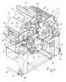
- Figures 1 to 4 show the machine to comprise an understructure 1 whose sides support rotatably the ends of mutually parallel rollers whose bottom arcs are tangent to a horizontal plane on which the sheet L to be painted travels.
- the rollers 2 are preferably covered with rubber of suitable hardness, such as about 50SH, and are connected kinematically by at least one chain 3 and sprockets, some of which are keyed to one end of the shafts of said rollers 2 and some of which are idle, as indicated at 104, to act as return and tensioning means.
- Said sprocket and chain drive 3, 4 is such that the rollers 2 travel in the same direction and with the same peripheral speed, so that the sheet L to be painted advances along them for example in the direction indicated by arrow F, from right to left, without friction between it and these rollers.
- roller 102 which is first to be contacted by the sheet L, is driven by a gearmotor 5 which, via the drive chain 3, 4 mentioned earlier, drives all the lower transfer roller system 2.
- roller 102 is also provided with means allowing it to be moved horizontally by an exact amount and then positioned eccentrically relative to the applicator roller above it, for known purposes which will be considered later.
- the end brackets 6 of the shaft of the roller 102 are mounted on the understructure 1 via horizontal guide and slide means 7 and on each side of the understructure 1 there are linear motion actuators 8, such as screw and nut actuators, synchronized with each other by a shaft 9 which is parallel to the axis of the roller system 2 and can be turned precisely by a handwheel 10 shown more clearly in Figure 3 and with motion display means (not shown).
- linear motion actuators 8 such as screw and nut actuators
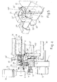
- a platform or table 11 mounted on which are the applicator rollers and the metering roller which form the so-called paint application head, which because of the vertical motion referred to earlier can be adapted to the different thicknesses of the sheet L to be painted and to the differing working requirements, as explained later.
- the table 11 may for example be mounted on the understructure 1 via four vertical linear motion actuators of for example the screw and nut type, as indicated at 12, which may be actuated by three speed-reducing and angle-drive units 13 connected together by three synchronizing shafts 14 and 114 and driven by a gearmotor 15 in which the speed reducer forms the fourth of said angle speed reducers and whose motor has a through shaft, with two directions of rotation and of the type having electronic control of speed and phase, so that it can be remotely controlled through a programming, command and control panel, not shown here because it is obvious to those skilled in the art.
- the screw and nut type as indicated at 12
- gearmotor 15 in which the speed reducer forms the fourth of said angle speed reducers and whose motor has a through shaft, with two directions of rotation and of the type having electronic control of speed and phase, so that it can be remotely controlled through a programming, command and control panel, not shown here because it is obvious to those skilled in the art.
- the rubber-coated applicator roller 17 is mounted rotatably about its axis with its end brackets 16 on the table 11 and lies parallel to its corresponding lower opposing roller 202, its function being to apply covering or satin paint.
- the surface of the elastomeric coating of the roller 17 may have a hardness of for example roughly 40SH and may be etched with lines which, depending on its intended use, may be around 26 lines per centimetre for applying covering paint, or around 60-80 lines per centimetre for applying satin paint.
- the axis of the roller 17 lies in a vertical plane which also contains the axis of the opposing roller 202 beneath it.
- the roller 17 is driven by a gearmotor 18 such that said applicator roller 17 can rotate on command with the same peripheral speed as the roller 202 and in the same direction F of advance as the sheet L.
- the rubber-coated roller 19 for the reverse-type application. Its elastomeric surface is similarly characterized by a hardness of around 40SH but, unlike the applicator roller 17 discussed above, it is ground smooth.
- the applicator roller 19 is driven by a gearmotor 20 which, when activated, turns it in the opposite direction to the direction F of advance of the sheet L with a velocity which can be varied electronically by means on said programming, command and control panel of the machine.
- the brackets 21 of the applicator roller 19 are mounted on bases 22 parallel to the table 11, which can on command be raised or lowered relative to said table by actuator means, e.g.
- cylinders 23 can be replaced by other means and that the vertical control of the roller 19 can instead be achieved, not by a rectilinear movement, but by an oscillating movement; these details will be obvious to those skilled in the art, who will have no trouble carrying them out.
- a metering roller 24 characterized by a smooth and usually chrome-plated surface and laid parallel to and in between the two applicator rollers 17 and 19.
- Linear motion means enable it to be placed with the correct amount of interference against either of the two applicator rollers 17, 19.
- the gearmotor 25 which turns the metering roller 24 has an electric motor with two directions of rotation and electronically controllable speed, so that the roller 24 can be set correctly to cooperate with applicator roller 17 or applicator roller 19.
- the brackets 26 which rotatably support the ends of the shaft of the roller 24 are mounted on the table 11 via means 27 of horizontal linear motion parallel to the motion F of the sheet to be processed and the sliding of these means 27 is connected to linear motion actuators 28, which may for example be of the screw and nut type, their body being fixed to the table 11 and connected to each other by a shaft 29.
- the latter is parallel to said rollers and can be operated by for example a handwheel 30 and/or a precision servo command operated remotely through the command and control panel of the machine.
- the machine When the machine is to be used for applications with the reverse roller 19, the latter is in the low position and, by adjusting the height of the elevator table 11, the distance between this roller 19 and its opposing roller 102 is adjusted to suit the thickness of the sheet L to be processed.
- the applicator roller 19 is set up with an appropriate amount of interference with the sheet so that it exerts on the sheet an appropriate contact pressure, which is a known amount. In this case, and still in relation to the thickness of the sheet and to any other parameters, the opposing roller 102 will be shifted horizontally so that there is a suitable misalignment between the latter and the applicator roller 19 above it.
- the applicator roller 17 is raised relative to the applicator roller 19 so that, besides being stationary because its motion unit 18 is off, the roller 17 is in a condition such as not to interfere in any way with the sheet L as it passes through.
- the metering roller 24 is brought up to the reverse applicator roller 19 with the desired amount of interference, and the paint to be applied to the sheet below it is fed into the trough V1 formed by the upper halves of the consecutive surfaces of these rollers 19 and 24, e.g. into the middle of this trough, by at least one tube or other suitable means 31.
- the amount of paint transferred onto the sheet will depend on the relative speeds of the applicator roller 19 and the sheet L and also on the so-called amount of interference between the applicator roller and the sheet L and between the applicator roller and the metering roller 24.
- brackets 32 which support, with the possibility of differentiated positioning and adjustment, by screw and nut or other control means 33, at least one doctor blade 34 which is placed against the surface of the metering roller when it leaves the trough V1, before this surface reaches the highest point of this roller, in order to force all the paint which follows this roller in its rotation to fall into the trough V1.
- the doctor blades will be discussed more fully at a later point in the description.
- the paint which may for example be satin effect paint
- the upstream applicator roller 19 is stationary and raised, as illustrated in Figure 2 .
- the metering roller 24 is placed against the applicator roller 17 with which it defines an upper trough V2 into which the paint is fed through a feed pipe 31'.
- the table 11 is set to the desired height so that the applicator roller 17 meets the upper face of the sheet L as it passes through, with an appropriate amount of interference.
- the applicator roller 17 draws paint from the bottom of the trough V2 and spreads it on the sheet L, keeping step with it as it advances in the direction F, without relative movements, other than those arising from the interference between the elastic surface of the roller 17 and the sheet L on its supporting opposing roller 202.
- the metering roller 24 is rotating in the opposite direction to the previous direction, so that its lateral surface is raised from the trough V2, while a doctor blade 34' is then positioned on the left of this roller 24, to force paint following the roller 24 to fall into the trough V2.
- the amount of paint spread on the sheet L depends in this case on the amount of interference between the metering roller 24 and the applicator roller and on the amount of interference between this same applicator roller and the sheet L.
- said walls 35, 35' may be provided with a drainage channel open at the bottom, and, as illustrated in Figures 4 and 6 , can discharge into hoppers 39, 39' which drain into a single collecting channel 40 on a transverse slope to drain the excess paint into the same container as that from which the feed pump draws the paint.
- hoppers 39, 39' ( Figure 6 ) have an elongate configuration that is also useful for collecting any paint that may drip from the edges of the applicator rollers and which stays on the latter due to the fact that they are not in contact underneath with the sheet.
- one or more continuous or discontinuous, straight or inclined auxiliary doctor blades 41, 41' may also be provided for appropriate cleaning of the applicator rollers 17, 19, or at least those parts of the surfaces of these rollers which engage with the feed troughs V1 or V2 but which do not engage with the sheet L.
- the walls 35, 35' may end at the top in a fork shape, as indicated at 135, which is useful for resting the paint supply tube 31 or 31', which will have an intermediate discharge or spaced-out discharge holes, so that this tube can easily be moved from one to the other of the troughs V1 and V2.
- the machine is completed by protective guards 42, 42' ( Figures 1-3 ) at opposite ends, where the sheets L enter and exit from the machine.
- the understructure 1 can be supported by metal wheels 43 on a track 44 laid on the ground and means are provided to allow, if required, the entire machine to be moved laterally out of the processing line for greater convenience during periodic maintenance and/or for replacement of parts.
Applications Claiming Priority (1)
| Application Number | Priority Date | Filing Date | Title |
|---|---|---|---|
| IT000161A ITBO20080161A1 (it) | 2008-03-13 | 2008-03-13 | Macchina combinata, particolarmente per la verniciatura di lastre di vetro, cristallo o di altre superfici piane in generale. |
Publications (2)
| Publication Number | Publication Date |
|---|---|
| EP2100672A2 true EP2100672A2 (de) | 2009-09-16 |
| EP2100672A3 EP2100672A3 (de) | 2012-02-22 |
Family
ID=40292647
Family Applications (1)
| Application Number | Title | Priority Date | Filing Date |
|---|---|---|---|
| EP09154977A Withdrawn EP2100672A3 (de) | 2008-03-13 | 2009-03-12 | Kombimaschine, insbesondere zum Bemalen von Glas-, Kristall- oder andere, flache Oberflächenplatten |
Country Status (3)
| Country | Link |
|---|---|
| US (1) | US20090229516A1 (de) |
| EP (1) | EP2100672A3 (de) |
| IT (1) | ITBO20080161A1 (de) |
Cited By (3)
| Publication number | Priority date | Publication date | Assignee | Title |
|---|---|---|---|---|
| CN101811104A (zh) * | 2010-03-26 | 2010-08-25 | 大连橡胶塑料机械股份有限公司 | 双工位涂胶装置 |
| CN102069056A (zh) * | 2010-12-25 | 2011-05-25 | 大连橡胶塑料机械股份有限公司 | 涂胶机精密涂胶控制系统 |
| WO2013030109A1 (de) * | 2011-09-01 | 2013-03-07 | Gebr. Schmid Gmbh | Vorrichtung und anlage zum bearbeiten von flachen substraten |
Families Citing this family (6)
| Publication number | Priority date | Publication date | Assignee | Title |
|---|---|---|---|---|
| CN105013666A (zh) * | 2015-09-02 | 2015-11-04 | 太仓市金新涂料有限公司 | 一种节能环保型油漆辊涂 |
| CN107570374B (zh) * | 2017-10-31 | 2023-03-21 | 常州工程职业技术学院 | 一种自动化控制的滚涂装置 |
| CN109822639B (zh) * | 2019-03-28 | 2023-12-15 | 豪德机械(上海)有限公司 | 一种链条传动的地板背部开槽设备 |
| EP3851209B1 (de) * | 2020-01-14 | 2024-03-06 | Jesús Francisco Barberan Latorre | Verfahren zum auftragen eines produktes mittels einer walze und auftragssystem |
| IT202100013085A1 (it) * | 2021-05-20 | 2022-11-20 | Cefla Soc Cooperativa | Apparato e metodo per la verniciatura a rullo di pannelli, preferibilmente pannelli fotovoltaici |
| CN115400912B (zh) * | 2022-03-28 | 2023-07-28 | 壹启新能源科技(苏州)有限公司 | 一种逆变器陶瓷片自动化涂胶装置及涂胶方法 |
Citations (2)
| Publication number | Priority date | Publication date | Assignee | Title |
|---|---|---|---|---|
| US3237597A (en) | 1962-08-13 | 1966-03-01 | Bovone Luigi | Roller device for the painting of glass or crystal plates, and of flat surfaces in general |
| JPS61171569A (ja) | 1984-12-28 | 1986-08-02 | Azuma Purekooto Kk | 高輝度反射塗装板の製造方法及びその方法を実施するための塗装々置 |
Family Cites Families (8)
| Publication number | Priority date | Publication date | Assignee | Title |
|---|---|---|---|---|
| US2681636A (en) * | 1951-01-15 | 1954-06-22 | Black Clawson Co | Paper coating machine |
| US3028260A (en) * | 1958-09-05 | 1962-04-03 | Ball Brothers Co Inc | Method of coating containers |
| US3131092A (en) * | 1961-09-06 | 1964-04-28 | Black Clawson Co | Apparatus for coating a moving web |
| US4796559A (en) * | 1985-09-04 | 1989-01-10 | Ulrich Steinemann Ag | Apparatus for applying a liquid to a web of material |
| DE4328011C2 (de) * | 1992-09-02 | 2000-08-24 | Basf Coatings Ag | Vorrichtung zum Mehrschichtlackieren von Blechtafeln |
| IT1287465B1 (it) * | 1996-07-29 | 1998-08-06 | Syfal Srl | Macchina rotativa per la smaltatura, in particolare di piastrelle ceramiche |
| US6011947A (en) * | 1997-09-29 | 2000-01-04 | Xerox Corporation | Apparatus and method for automatically adjusting water film thickness on conditioner metering rolls |
| US7329437B2 (en) * | 2001-08-17 | 2008-02-12 | Fujifilm Corporation | Coating method and coating apparatus |
-
2008
- 2008-03-13 IT IT000161A patent/ITBO20080161A1/it unknown
-
2009
- 2009-03-12 EP EP09154977A patent/EP2100672A3/de not_active Withdrawn
- 2009-03-12 US US12/402,564 patent/US20090229516A1/en not_active Abandoned
Patent Citations (2)
| Publication number | Priority date | Publication date | Assignee | Title |
|---|---|---|---|---|
| US3237597A (en) | 1962-08-13 | 1966-03-01 | Bovone Luigi | Roller device for the painting of glass or crystal plates, and of flat surfaces in general |
| JPS61171569A (ja) | 1984-12-28 | 1986-08-02 | Azuma Purekooto Kk | 高輝度反射塗装板の製造方法及びその方法を実施するための塗装々置 |
Cited By (4)
| Publication number | Priority date | Publication date | Assignee | Title |
|---|---|---|---|---|
| CN101811104A (zh) * | 2010-03-26 | 2010-08-25 | 大连橡胶塑料机械股份有限公司 | 双工位涂胶装置 |
| CN102069056A (zh) * | 2010-12-25 | 2011-05-25 | 大连橡胶塑料机械股份有限公司 | 涂胶机精密涂胶控制系统 |
| WO2013030109A1 (de) * | 2011-09-01 | 2013-03-07 | Gebr. Schmid Gmbh | Vorrichtung und anlage zum bearbeiten von flachen substraten |
| CN103765572A (zh) * | 2011-09-01 | 2014-04-30 | 德国施密特兄弟有限公司 | 用于处理平面基板的设备和系统 |
Also Published As
| Publication number | Publication date |
|---|---|
| EP2100672A3 (de) | 2012-02-22 |
| US20090229516A1 (en) | 2009-09-17 |
| ITBO20080161A1 (it) | 2009-09-14 |
Similar Documents
| Publication | Publication Date | Title |
|---|---|---|
| EP2100672A2 (de) | Kombimaschine, insbesondere zum Bemalen von Glas-, Kristall- oder andere, flache Oberflächenplatten | |
| US4606383A (en) | Battery grid pasting machine | |
| CN102773269B (zh) | 板材轧制输送装置及其控制方法 | |
| CN103625680A (zh) | 电梯导轨自动涂油贴膜生产线 | |
| CN108311336B (zh) | 一种涂布机 | |
| CN104369515B (zh) | 一种立式玻璃覆膜机 | |
| CN109351525A (zh) | 自动喷漆机 | |
| US4308945A (en) | Apparatus for transversely conveying profiled rods and rails | |
| CN208698173U (zh) | 一种自动化导光板热压转印及覆膜一体设备 | |
| JPH04216099A (ja) | 製本ブロックの丸み出しを行う製本機 | |
| CN109049958A (zh) | 一种自动化导光板热压转印及覆膜一体设备 | |
| CN208882737U (zh) | 一种带有张紧装置的输送带 | |
| CN116729757A (zh) | 一种具有防偏移功能的分卡自动平面贴标机 | |
| CN208730427U (zh) | 内外墙装饰板的生产加工设备 | |
| CN204309349U (zh) | 一种立式玻璃覆膜机 | |
| US3774905A (en) | Sheet feeding apparatus for coating machines | |
| CN213133800U (zh) | 一种复合板滚涂机 | |
| CN209222459U (zh) | 自动喷漆机 | |
| CN205146582U (zh) | 快速换辊微凹涂布机 | |
| CN204724392U (zh) | 一种直线带包角式涂敷装置 | |
| GB2151392A (en) | Battery grid pasting machine | |
| CN211303676U (zh) | 一种汽车顶棚湿法成型系统 | |
| CN219339019U (zh) | 一种上光喷码一体机 | |
| CN213435402U (zh) | 一种木板加工腻子刮灰机 | |
| CN219634748U (zh) | 一种凹板印刷机构 |
Legal Events
| Date | Code | Title | Description |
|---|---|---|---|
| PUAI | Public reference made under article 153(3) epc to a published international application that has entered the european phase |
Free format text: ORIGINAL CODE: 0009012 |
|
| AK | Designated contracting states |
Kind code of ref document: A2 Designated state(s): AT BE BG CH CY CZ DE DK EE ES FI FR GB GR HR HU IE IS IT LI LT LU LV MC MK MT NL NO PL PT RO SE SI SK TR |
|
| AX | Request for extension of the european patent |
Extension state: AL BA RS |
|
| PUAL | Search report despatched |
Free format text: ORIGINAL CODE: 0009013 |
|
| AK | Designated contracting states |
Kind code of ref document: A3 Designated state(s): AT BE BG CH CY CZ DE DK EE ES FI FR GB GR HR HU IE IS IT LI LT LU LV MC MK MT NL NO PL PT RO SE SI SK TR |
|
| AX | Request for extension of the european patent |
Extension state: AL BA RS |
|
| RIC1 | Information provided on ipc code assigned before grant |
Ipc: B05C 1/02 20060101ALI20120113BHEP Ipc: B05C 1/08 20060101AFI20120113BHEP |
|
| AKY | No designation fees paid | ||
| REG | Reference to a national code |
Ref country code: DE Ref legal event code: R108 Effective date: 20121031 |
|
| STAA | Information on the status of an ep patent application or granted ep patent |
Free format text: STATUS: THE APPLICATION IS DEEMED TO BE WITHDRAWN |
|
| 18D | Application deemed to be withdrawn |
Effective date: 20120823 |