EP2097913B1 - Verfahren zur herstellung eines festen magnetkreisbauteils - Google Patents
Verfahren zur herstellung eines festen magnetkreisbauteils Download PDFInfo
- Publication number
- EP2097913B1 EP2097913B1 EP07820538.2A EP07820538A EP2097913B1 EP 2097913 B1 EP2097913 B1 EP 2097913B1 EP 07820538 A EP07820538 A EP 07820538A EP 2097913 B1 EP2097913 B1 EP 2097913B1
- Authority
- EP
- European Patent Office
- Prior art keywords
- main body
- magnetic circuit
- magnetic
- heat treatment
- circuit component
- Prior art date
- Legal status (The legal status is an assumption and is not a legal conclusion. Google has not performed a legal analysis and makes no representation as to the accuracy of the status listed.)
- Not-in-force
Links
Images


Classifications
-
- H—ELECTRICITY
- H01—ELECTRIC ELEMENTS
- H01F—MAGNETS; INDUCTANCES; TRANSFORMERS; SELECTION OF MATERIALS FOR THEIR MAGNETIC PROPERTIES
- H01F41/00—Apparatus or processes specially adapted for manufacturing or assembling magnets, inductances or transformers; Apparatus or processes specially adapted for manufacturing materials characterised by their magnetic properties
- H01F41/02—Apparatus or processes specially adapted for manufacturing or assembling magnets, inductances or transformers; Apparatus or processes specially adapted for manufacturing materials characterised by their magnetic properties for manufacturing cores, coils, or magnets
- H01F41/0206—Manufacturing of magnetic cores by mechanical means
-
- H—ELECTRICITY
- H01—ELECTRIC ELEMENTS
- H01F—MAGNETS; INDUCTANCES; TRANSFORMERS; SELECTION OF MATERIALS FOR THEIR MAGNETIC PROPERTIES
- H01F7/00—Magnets
- H01F7/06—Electromagnets; Actuators including electromagnets
- H01F7/08—Electromagnets; Actuators including electromagnets with armatures
- H01F7/081—Magnetic constructions
- H01F2007/085—Yoke or polar piece between coil bobbin and armature having a gap, e.g. filled with nonmagnetic material
-
- H—ELECTRICITY
- H01—ELECTRIC ELEMENTS
- H01F—MAGNETS; INDUCTANCES; TRANSFORMERS; SELECTION OF MATERIALS FOR THEIR MAGNETIC PROPERTIES
- H01F3/00—Cores, Yokes, or armatures
- H01F3/10—Composite arrangements of magnetic circuits
-
- H—ELECTRICITY
- H01—ELECTRIC ELEMENTS
- H01F—MAGNETS; INDUCTANCES; TRANSFORMERS; SELECTION OF MATERIALS FOR THEIR MAGNETIC PROPERTIES
- H01F7/00—Magnets
- H01F7/06—Electromagnets; Actuators including electromagnets
- H01F7/08—Electromagnets; Actuators including electromagnets with armatures
- H01F7/127—Assembling
-
- Y—GENERAL TAGGING OF NEW TECHNOLOGICAL DEVELOPMENTS; GENERAL TAGGING OF CROSS-SECTIONAL TECHNOLOGIES SPANNING OVER SEVERAL SECTIONS OF THE IPC; TECHNICAL SUBJECTS COVERED BY FORMER USPC CROSS-REFERENCE ART COLLECTIONS [XRACs] AND DIGESTS
- Y10—TECHNICAL SUBJECTS COVERED BY FORMER USPC
- Y10T—TECHNICAL SUBJECTS COVERED BY FORMER US CLASSIFICATION
- Y10T29/00—Metal working
- Y10T29/49—Method of mechanical manufacture
- Y10T29/49002—Electrical device making
- Y10T29/49117—Conductor or circuit manufacturing
- Y10T29/49124—On flat or curved insulated base, e.g., printed circuit, etc.
- Y10T29/49155—Manufacturing circuit on or in base
- Y10T29/49163—Manufacturing circuit on or in base with sintering of base
-
- Y—GENERAL TAGGING OF NEW TECHNOLOGICAL DEVELOPMENTS; GENERAL TAGGING OF CROSS-SECTIONAL TECHNOLOGIES SPANNING OVER SEVERAL SECTIONS OF THE IPC; TECHNICAL SUBJECTS COVERED BY FORMER USPC CROSS-REFERENCE ART COLLECTIONS [XRACs] AND DIGESTS
- Y10—TECHNICAL SUBJECTS COVERED BY FORMER USPC
- Y10T—TECHNICAL SUBJECTS COVERED BY FORMER US CLASSIFICATION
- Y10T29/00—Metal working
- Y10T29/49—Method of mechanical manufacture
- Y10T29/49002—Electrical device making
- Y10T29/49117—Conductor or circuit manufacturing
- Y10T29/49169—Assembling electrical component directly to terminal or elongated conductor
Definitions
- the invention is based on a method for producing a fixed magnetic circuit component according to the preamble of the main claim.
- FIG. 1 a known fuel injection valve of the prior art is shown, which has a classic three-part construction of an inner metal flow guide member and at the same time housing component.
- This inner valve tube is formed from an inlet port forming an inner pole, a nonmagnetic intermediate part and a valve seat carrier receiving a valve seat, and in the description FIG. 1 explained in more detail.
- a valve housing produced in this way can be used, for example, in magnetic valves for anti-lock braking systems (ABS) of motor vehicles.
- the methods are characterized by providing, directly or through previous conversion processes, a one-piece sleeve-shaped magnetic martensitic workpiece which undergoes a local heat treatment in a central portion of the magnetic martensitic workpiece to convert that middle portion into a non-magnetic, austenitic center portion , Alternatively, in the local heat treatment by laser, molten austenite-forming elements are added to the site of the heat treatment to form a nonmagnetic austenitic central portion of the solid core.
- a method for producing a fixed magnetic circuit component for an electromagnetically operable valve is already known, wherein the magnetic circuit component has at least two zones and in each case two immediately following zones have different magnetic properties.
- a cup-shaped base of a magnetic or magnetizable material is provided.
- a complete first heat treatment of the body is made, followed by a local second heat treatment of the body to form a portion with a structure of martensite and retained austenite in the otherwise martensitic body.
- the base body thus treated is finally installed as a magnetic circuit component in a magnetic circuit of an electromagnetically actuated valve.
- a magnetic separation point is present within the otherwise martensitic cup-shaped basic body over the entire thickness of the thin-walled base body around which the magnetic field lines of the magnetic circuit are led in order to attract a magnetic armature against a fixed inner pole when a magnetic coil is energized.
- the cup-shaped base body is a stationary valve component part of the fixed outer magnetic circuit.
- the inventive method for producing a fixed magnetic circuit component with the characterizing features of the main claim has the advantage that in a very simple and cost-effective manner housing with a magnetic separation or magnetic circuit components with locally adjusted magnetic properties, especially in edge layers mass produced reliably.
- FIG. 1 a fuel injection valve according to the prior art with a three-piece inner metal valve tube as a housing
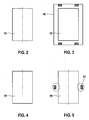
- FIGS. 2 to 7 FIG. 2 schematically shows method steps of a known method for producing a fixed magnetic circuit component in the form of a tubular housing
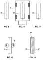
- FIG. FIG. 8 a schematic section of an injection valve with such a case
- FIGS. 9 to 13 schematically process steps of the method according to the invention for the production of a fixed magnetic circuit component in the form of an anchor bolt
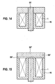
- FIG. 14 a schematic section of a magnetic circuit in Tauchankeraus entry with an anchor bolt made according to the invention
- FIG. 15 a schematic section of a magnetic circuit in Flachankeraus arrangement with an anchor plate produced according to the invention.
- FIGS. 2 to 15 Before using the FIGS. 2 to 15 the method steps of the method for producing a fixed magnetic circuit component will be described with reference to FIG. 1 a fuel injection valve of the prior art as a possible input product for a magnetic circuit component produced according to the invention will be explained in more detail.
- electromagnetically operable valve in the form of an injector for fuel injection systems of mixture-compressing spark-ignition internal combustion engines has a surrounded by a magnetic coil 1, serving as a fuel inlet nozzle and inner pole tubular core 2, for example, has over its entire length a constant outer diameter.
- a coil body 3 stepped in the radial direction accommodates a winding of the magnet coil 1 and, in conjunction with the core 2, enables a compact construction of the injection valve in the region of the magnet coil 1.
- a lower core end 9 of the core 2 is concentric with a valve longitudinal axis 10 tightly connected to a tubular metal non-magnetic intermediate part 12 by welding and surrounds the core end 9 partially axially.
- a tubular valve seat support 16 Downstream of the bobbin 3 and the intermediate part 12 extends a tubular valve seat support 16 which is fixedly connected to the intermediate part 12.
- an axially movable valve needle 18 is arranged in the valve seat carrier 16.
- a spherical valve closing body 24 is provided, on whose circumference, for example, five flats 25 are provided for flowing past the fuel.
- the actuation of the injection valve takes place in a known manner electromagnetically.
- the electromagnetic circuit is used with the solenoid 1, the core 2 and an armature 27.
- the tubular armature 27 is facing away with a valve closing body 24
- End of the valve needle 18 firmly connected by, for example, a weld and aligned with the core 2.
- the core 2 opposite end of the valve seat carrier 16 is a cylindrical valve seat body 29 having a fixed valve seat 30, mounted by welding tight.
- the spherical valve closing body 24 of the valve needle 18 cooperates with the valve seat 30 of the valve seat body 29, which tapers frustoconically in the flow direction.
- At its lower end face of the valve seat body 29 with an example cup-shaped spray orifice plate 34 is solid and tight by a z. B. connected by means of a laser weld.
- In the spray perforated disk 34 at least one, for example, four ejection openings 39 formed by eroding or punching are provided.
- the magnetic coil 1 of at least one, for example, designed as a bracket and serving as a ferromagnetic element guide element Surrounded surrounding the solenoid coil 1 in the circumferential direction at least partially and with its one end to the core 2 and its other end rests against the valve seat carrier 16 and with these z. B. is connected by welding, soldering or gluing.
- valve tube is the classic three-part structure of a housing for an electromagnetically actuated unit, such as a valve, with two ferromagnetic or magnetizable housing portions, which is effective for effective guidance of the magnetic circuit lines in the region of the armature 27 by means of a non-magnetic intermediate part 12 separated from each other or at least connected to each other via a magnetic throttle.
- the injection valve is largely surrounded by a plastic extrusion coating 51, which extends from the core 2 in the axial direction via the magnetic coil 1 and the at least one guide element 45 to the valve seat carrier 16, wherein the at least one guide element 45 is completely covered axially and in the circumferential direction.
- a mitangespritzter electrical connector 52 belongs to this plastic extrusion 51.
- FIGS. 2 to 7 schematically indicated process steps of not covered by the scope of the method for producing a fixed magnetic circuit component, it is possible in an advantageous manner, particularly simple and inexpensive thin-walled housing 66 for a variety of purposes, including preferably produce electromagnetically operable valves that can replace a three-piece valve tube described above.
- an example cylindrical base body 55 is provided from which the housing 66 is to be made and which consists of a magnetic or magnetizable material and is eg ferromagnetic or ferritic or has a martensitic material structure.
- the main body 55 may initially be solid and, for example, be obtained for a particularly effective production of many cases 66 of long bar material.
- the material of the main body 55 is in any case a steel which forms residual austenite and martensite due to its alloy composition. Alloy elements in the material are the austenite-stabilizing elements C, N, Ni and Mn.
- the base body 55 is completely subjected to a heat treatment, which can be carried out in ovens 56 by hardening, freezing in freezers and / or by tempering once or several times ( FIG. 3 ).
- a heat treatment can be carried out in ovens 56 by hardening, freezing in freezers and / or by tempering once or several times ( FIG. 3 ).
- the microstructure can also consist of retained austenite parts, which are converted into martensite by the subsequent heat treatment steps.
- the microstructure may also consist of ferrite with embedded particles such as carbides, nitrides or intermetallic compounds.
- the heat treatment takes place in such a way that a completely magnetic martensitic material structure is formed in the main body 55 ( FIG. 4 ).
- a further heat treatment is performed, which, however, is carried out only locally limited.
- a partial area of the main body 55 is exposed to a short-time heat treatment by means of laser or induction heating 57 (FIG. FIG. 5 ).
- the material of the base body 55 is locally austenitized and homogenized in the portion of the second heat treatment and consists after cooling of the body 55 or the self-quenching by the surrounding material of martensitic areas 58 and the subarea 59 with martensite and retained austenite ( FIG. 6 ).
- the main body 55 now consists of zones with different structures and magnetic properties.
- the base body 55 is subsequently finished so that a solid housing 66 is present as a magnetic circuit component in a desired geometry.
- a housing 66 produced according to the invention in a fuel injection valve, it may be advantageous to mold the housing 66 specifically by manufacturing measures such as stretching, rolling, swaging, crimping and / or Auftulpen.
- the housing 66 is a component which, in a known fuel injection valve according to FIG. 1 the sum of the functions of the valve tube consisting of the core 2, intermediate part 12 and valve seat carrier 16 can completely take over and thus extends, for example, over the entire axial length of a fuel injection valve.
- the massive body 55 is brought by manufacturing measures, for example in a tubular sleeve shape.
- the massive body 55 can either before or only after the local heat treatment with an inner longitudinal opening 60 to form the tubular housing 66 are provided ( FIG. 7 ).
- FIG. 8 shows a schematic section of a fuel injector with a housing 66 produced according to the invention, which is installed as a thin-walled sleeve in the valve and thereby surrounds the core 2 and the armature 27 radially and circumferentially and is itself surrounded by the magnetic coil 1. It is clear that the changed in its magnetic properties and martensitic and rest austenitic portion 59 of the housing 66 in the axial extension of a working air gap 70 between the core 2 and the armature 27 is to guide the magnetic circuit lines optimally and effectively in the magnetic circuit. Instead of in FIG.
- the outer magnetic circuit component is designed for example as a magnetic pot 46, wherein the magnetic circuit between the magnetic pot 46 and the housing 66 is closed by a cover member 47.
- the inventive method also makes it possible to locally change housing 66 with larger wall thicknesses in their magnetic properties, so that a higher internal pressure resistance while still minimizing the magnetically active area is ensured in favor of the magnetic force.
- FIGS. 9 to 13 schematically show process steps of the inventive method for producing a fixed magnetic circuit component in the form of an anchor bolt 66 '.
- the manufacture of the anchor bolt 66 ' takes place in a manner comparable to the previously described production of the housing 66 according to FIG FIG. 7 .
- a first process step for example, a thin cylindrical base body 55 'is provided, from which the anchor bolt 66' is to be manufactured and which consists of a magnetic or magnetizable material and is eg ferromagnetic or ferritic or has a martensitic material structure.
- the main body 55 ' can be obtained, for example, for a particularly effective production of many anchor bolts 66' of long bar material.
- the material of the main body 55 ' is in any case a steel which forms retained austenite and martensite due to its alloy composition. Alloy elements in the material are the austenite-stabilizing elements C, N, Ni and Mn.
- the microstructure can also consist of retained austenite parts, which are converted into martensite by the subsequent heat treatment steps.
- the microstructure may also consist of ferrite with embedded particles such as carbides, nitrides or intermetallic compounds.
- the heat treatment takes place in such a way that a completely magnetic martensitic material structure is formed in the main body 55 '( FIG. 11 ).
- a further heat treatment is performed, which is to lead exclusively to the surface in the edge regions of the base body 55 'to a change in the magnetic properties.
- the surface of the main body 55 ' is subjected to a short-time heat treatment by means of laser or induction heating 57 ( FIG. 12 ).
- the material of the base body 55 ' is austenitized locally on the surface and homogenized and consists after cooling of the body 55' and the self-quenching by the surrounding material of an inner martensitic region 58 'and an outer edge region 59' with martensite and Retained austenite ( FIG. 13 ).
- the main body 55 'or the anchor bolt 66' now consists of zones with different structures and magnetic properties.
- FIG. 14 shows a schematic section of a magnetic circuit in Tauchankeraus operation with an anchor bolt 66 'produced according to the invention, which dives through a magnet coil 1 enveloping magnetic pot 46 and is movable there.
- the dynamics and the magnetic force of the solenoid valve can be improved with an anchor bolt 66 'in which the outer edge region 59' has retained austenite components. Coating processes, such as carbonitriding, can be dispensed with.
- FIG. 15 2 shows a schematic section of a magnetic circuit in flat armature design with an armature plate 66 "produced according to the invention. comparable.
- the local second heat treatment is carried out in such a way that on one side of the flat plate-shaped base body, a short-time heat treatment is carried out by means of laser or induction heating.
- the material of the body is locally austenitized and homogenized on this side and consists after cooling of the body or the self-quenching by the surrounding material of a martensitic region 58 "and the magnetic coil 1 facing edge region 59" with martensite and retained austenite.
- the anchor plate 66 now consists of zones with different structures and magnetic properties.
- This additional air gap in the edge region 59 can be used to prevent the anchor plate 66" from sticking to the magnetic pot 46 in order to set a defined residual air gap in the magnetic circuit or as an air gap To serve wear protection.
- the invention is by no means limited to use in fuel injection valves or solenoid valves for anti-lock braking systems, but relates to all electromagnetically actuated valves of different application areas and generally all solid housing in units in which zones of different magnetism are sequentially required.
Landscapes
- Engineering & Computer Science (AREA)
- Power Engineering (AREA)
- Manufacturing & Machinery (AREA)
- Magnetically Actuated Valves (AREA)
- Fuel-Injection Apparatus (AREA)
- Insulating Of Coils (AREA)
- Electromagnets (AREA)
- Forging (AREA)
Applications Claiming Priority (2)
| Application Number | Priority Date | Filing Date | Title |
|---|---|---|---|
| DE102006055010A DE102006055010A1 (de) | 2006-11-22 | 2006-11-22 | Verfahren zur Herstellung eines Magnetkreisbauteils |
| PCT/EP2007/060132 WO2008061829A1 (de) | 2006-11-22 | 2007-09-25 | Verfahren zur herstellung eines festen magnetkreisbauteils |
Publications (2)
| Publication Number | Publication Date |
|---|---|
| EP2097913A1 EP2097913A1 (de) | 2009-09-09 |
| EP2097913B1 true EP2097913B1 (de) | 2014-02-26 |
Family
ID=38626542
Family Applications (1)
| Application Number | Title | Priority Date | Filing Date |
|---|---|---|---|
| EP07820538.2A Not-in-force EP2097913B1 (de) | 2006-11-22 | 2007-09-25 | Verfahren zur herstellung eines festen magnetkreisbauteils |
Country Status (5)
| Country | Link |
|---|---|
| US (1) | US8245394B2 (ja) |
| EP (1) | EP2097913B1 (ja) |
| JP (2) | JP5279719B2 (ja) |
| DE (1) | DE102006055010A1 (ja) |
| WO (1) | WO2008061829A1 (ja) |
Families Citing this family (8)
| Publication number | Priority date | Publication date | Assignee | Title |
|---|---|---|---|---|
| DE102008040549A1 (de) * | 2008-07-18 | 2010-01-21 | Robert Bosch Gmbh | Verfahren zur Herstellung eines metallischen Verbundbauteils, insbesondere für ein elektromagnetisches Ventil |
| DE102008040545A1 (de) * | 2008-07-18 | 2010-01-21 | Robert Bosch Gmbh | Metallisches Verbundbauteil, insbesondere für ein elektromagnetisches Ventil |
| DE102009055154A1 (de) | 2009-12-22 | 2011-06-30 | Robert Bosch GmbH, 70469 | Magnetische Trennung für Magnetventil |
| DE102011084724A1 (de) | 2011-10-18 | 2013-04-18 | Robert Bosch Gmbh | Verfahren zur Herstellung einer magnetischen Trennung für ein Magnetventil |
| DE102012023394A1 (de) | 2012-11-30 | 2014-06-05 | Robert Bosch Gmbh | Eisenbasierte Legierung, daraus hergestelltes Halbzeug oder Bauteil mit magnetischem Trennbereich, und Verfahren zu deren Herstellung |
| EP2775132A1 (en) | 2013-03-07 | 2014-09-10 | Continental Automotive GmbH | Valve body and fluid injector |
| EP2832867B1 (en) * | 2013-08-02 | 2016-06-01 | Continental Automotive GmbH | Method for producing a valve body for an electromechanically operable valve, a valve body, and an electromechanically operable valve comprising the valve body |
| WO2018216603A1 (ja) * | 2017-05-22 | 2018-11-29 | 日立金属株式会社 | 比例ソレノイド、その製造方法、および、比例ソレノイドの特性制御方法 |
Family Cites Families (14)
| Publication number | Priority date | Publication date | Assignee | Title |
|---|---|---|---|---|
| AU5736573A (en) | 1973-06-26 | 1975-01-09 | Tsentralny Ordona Trudovogo Krasnogo Znameni Nauchno-Issledovatelsky Institut Chernyi Metallurgii Imerti Ip. Bardina | Method of producing articles with alternating magnetic and nonmagnetic portions from continuous metal blanks |
| US4604600A (en) * | 1983-12-23 | 1986-08-05 | G. W. Lisk Company, Inc. | Solenoid construction and method for making the same |
| DE3502287A1 (de) | 1985-01-24 | 1986-07-24 | Robert Bosch Gmbh, 7000 Stuttgart | Verfahren zur herstellung eines rotationssymmetrischen gehaeuses, insbesondere eines ventilgehaeuses |
| JP2989977B2 (ja) * | 1991-12-17 | 1999-12-13 | 三菱電機株式会社 | 燃料噴射装置の固定鉄心の製造方法 |
| JPH05164012A (ja) * | 1991-12-17 | 1993-06-29 | Mitsubishi Electric Corp | 燃料噴射装置及びその固定鉄心の製造方法 |
| DE4237405C3 (de) * | 1991-12-17 | 2003-10-30 | Mitsubishi Electric Corp | Kraftstoffeinspritzvorrichtung für eine Brennkraftmaschine und Verfahren zur Herstellung eines festen Kerns für diese Einspritzvorrichtung |
| JP3311427B2 (ja) | 1993-06-18 | 2002-08-05 | 株式会社デンソー | 複合磁性部材およびその製法およびこの複合磁性部材を用いた電磁弁 |
| JP3868019B2 (ja) * | 1995-12-07 | 2007-01-17 | 日立金属株式会社 | 複合磁性部材およびその製造方法 |
| JPH11132127A (ja) * | 1996-11-13 | 1999-05-18 | Denso Corp | 燃料噴射弁及びその組立方法 |
| JPH10227266A (ja) * | 1997-02-14 | 1998-08-25 | Denso Corp | 燃料噴射弁 |
| US5944262A (en) * | 1997-02-14 | 1999-08-31 | Denso Corporation | Fuel injection valve and its manufacturing method |
| JPH11251138A (ja) * | 1998-03-04 | 1999-09-17 | Daido Steel Co Ltd | 電磁コイル用スリーブ材およびその製造方法 |
| JP4623984B2 (ja) * | 2004-03-24 | 2011-02-02 | 株式会社ケーヒン | リニアソレノイドバルブ |
| US7611590B2 (en) * | 2004-07-08 | 2009-11-03 | Alloy Technology Solutions, Inc. | Wear resistant alloy for valve seat insert used in internal combustion engines |
-
2006
- 2006-11-22 DE DE102006055010A patent/DE102006055010A1/de not_active Ceased
-
2007
- 2007-09-25 WO PCT/EP2007/060132 patent/WO2008061829A1/de active Application Filing
- 2007-09-25 EP EP07820538.2A patent/EP2097913B1/de not_active Not-in-force
- 2007-09-25 US US12/312,694 patent/US8245394B2/en not_active Expired - Fee Related
- 2007-09-25 JP JP2009537575A patent/JP5279719B2/ja not_active Expired - Fee Related
-
2012
- 2012-03-16 JP JP2012060977A patent/JP5627623B2/ja not_active Expired - Fee Related
Also Published As
| Publication number | Publication date |
|---|---|
| JP5627623B2 (ja) | 2014-11-19 |
| US8245394B2 (en) | 2012-08-21 |
| JP2010510458A (ja) | 2010-04-02 |
| US20100126007A1 (en) | 2010-05-27 |
| JP5279719B2 (ja) | 2013-09-04 |
| JP2012163208A (ja) | 2012-08-30 |
| WO2008061829A1 (de) | 2008-05-29 |
| DE102006055010A1 (de) | 2008-05-29 |
| EP2097913A1 (de) | 2009-09-09 |
Similar Documents
| Publication | Publication Date | Title |
|---|---|---|
| EP1919655B1 (de) | Verfahren zur herstellung eines festen gehäuses | |
| EP1919654B1 (de) | Verfahren zur herstellung eines festen gehäuses | |
| EP2097913B1 (de) | Verfahren zur herstellung eines festen magnetkreisbauteils | |
| EP2313896B1 (de) | Metallisches verbundbauteil, insbesondere für ein elektromagnetisches ventil | |
| EP0720691B1 (de) | Ventilnadel für ein elektromagnetisch betätigbares ventil und verfahren zur herstellung | |
| DE4310719C2 (de) | Verfahren zur Herstellung eines Magnetkreises für ein Ventil | |
| DE102005061424A1 (de) | Brennstoffeinspritzventil | |
| EP0733162A1 (de) | Verfahren zur herstellung eines magnetkreises für ein ventil | |
| WO2000040855A1 (de) | Brennstoffeinspritzventil | |
| EP2304741B1 (de) | Verfahren zur herstellung eines metallischen verbundbauteils, insbesondere für ein elektromagnetisches ventil | |
| DE102009055133A1 (de) | Polkern für Magnetventile hergestellt mittels Mehrstoff-MIM | |
| EP0937200B1 (de) | Elektromagnetisch betätigbares ventil | |
| EP1699578B1 (de) | Verfahren zur herstellung eines hülsenförmigen gehäuses aus mehreren flachen blechen | |
| DE102005037951A1 (de) | Verfahren zur Herstellung eines festen Gehäuses | |
| DE102008040550A1 (de) | Verfahren zur Herstellung eines metallischen Verbundbauteils, insbesondere für ein elektromagnetisches Ventil | |
| EP2320062B1 (de) | Einspritzventil und Herstellungsverfahren desselben | |
| DE102012210956A1 (de) | Verfahren zur Herstellung eines Gehäuses, insbesondere eines Ventilgehäuses | |
| DE102007050819A1 (de) | Elektromagnetisch betätigbares Ventil | |
| DE102008040543A1 (de) | Verfahren zur Herstellung eines metallischen Verbundbauteils, insbesondere für ein elektromagnetisches Ventil | |
| DE102004044821A1 (de) | Brennstoffeinspritzventil und Verfahren zu dessen Herstellung | |
| DE102010000797A1 (de) | Massivumformen einer magnetischen Trennung | |
| DE102007050814B4 (de) | Brennstoffeinspritzventil |
Legal Events
| Date | Code | Title | Description |
|---|---|---|---|
| PUAI | Public reference made under article 153(3) epc to a published international application that has entered the european phase |
Free format text: ORIGINAL CODE: 0009012 |
|
| 17P | Request for examination filed |
Effective date: 20090622 |
|
| AK | Designated contracting states |
Kind code of ref document: A1 Designated state(s): AT BE BG CH CY CZ DE DK EE ES FI FR GB GR HU IE IS IT LI LT LU LV MC MT NL PL PT RO SE SI SK TR |
|
| 17Q | First examination report despatched |
Effective date: 20090917 |
|
| DAX | Request for extension of the european patent (deleted) | ||
| GRAP | Despatch of communication of intention to grant a patent |
Free format text: ORIGINAL CODE: EPIDOSNIGR1 |
|
| INTG | Intention to grant announced |
Effective date: 20131114 |
|
| GRAS | Grant fee paid |
Free format text: ORIGINAL CODE: EPIDOSNIGR3 |
|
| GRAA | (expected) grant |
Free format text: ORIGINAL CODE: 0009210 |
|
| AK | Designated contracting states |
Kind code of ref document: B1 Designated state(s): AT BE BG CH CY CZ DE DK EE ES FI FR GB GR HU IE IS IT LI LT LU LV MC MT NL PL PT RO SE SI SK TR |
|
| REG | Reference to a national code |
Ref country code: GB Ref legal event code: FG4D Free format text: NOT ENGLISH |
|
| REG | Reference to a national code |
Ref country code: CH Ref legal event code: EP |
|
| REG | Reference to a national code |
Ref country code: AT Ref legal event code: REF Ref document number: 654009 Country of ref document: AT Kind code of ref document: T Effective date: 20140315 |
|
| REG | Reference to a national code |
Ref country code: DE Ref legal event code: R096 Ref document number: 502007012793 Country of ref document: DE Effective date: 20140403 |
|
| REG | Reference to a national code |
Ref country code: IE Ref legal event code: FG4D Free format text: LANGUAGE OF EP DOCUMENT: GERMAN |
|
| REG | Reference to a national code |
Ref country code: NL Ref legal event code: VDEP Effective date: 20140226 |
|
| REG | Reference to a national code |
Ref country code: LT Ref legal event code: MG4D |
|
| PG25 | Lapsed in a contracting state [announced via postgrant information from national office to epo] |
Ref country code: LT Free format text: LAPSE BECAUSE OF FAILURE TO SUBMIT A TRANSLATION OF THE DESCRIPTION OR TO PAY THE FEE WITHIN THE PRESCRIBED TIME-LIMIT Effective date: 20140226 Ref country code: IS Free format text: LAPSE BECAUSE OF FAILURE TO SUBMIT A TRANSLATION OF THE DESCRIPTION OR TO PAY THE FEE WITHIN THE PRESCRIBED TIME-LIMIT Effective date: 20140626 |
|
| PG25 | Lapsed in a contracting state [announced via postgrant information from national office to epo] |
Ref country code: CY Free format text: LAPSE BECAUSE OF FAILURE TO SUBMIT A TRANSLATION OF THE DESCRIPTION OR TO PAY THE FEE WITHIN THE PRESCRIBED TIME-LIMIT Effective date: 20140226 Ref country code: FI Free format text: LAPSE BECAUSE OF FAILURE TO SUBMIT A TRANSLATION OF THE DESCRIPTION OR TO PAY THE FEE WITHIN THE PRESCRIBED TIME-LIMIT Effective date: 20140226 Ref country code: PT Free format text: LAPSE BECAUSE OF FAILURE TO SUBMIT A TRANSLATION OF THE DESCRIPTION OR TO PAY THE FEE WITHIN THE PRESCRIBED TIME-LIMIT Effective date: 20140626 Ref country code: NL Free format text: LAPSE BECAUSE OF FAILURE TO SUBMIT A TRANSLATION OF THE DESCRIPTION OR TO PAY THE FEE WITHIN THE PRESCRIBED TIME-LIMIT Effective date: 20140226 Ref country code: SE Free format text: LAPSE BECAUSE OF FAILURE TO SUBMIT A TRANSLATION OF THE DESCRIPTION OR TO PAY THE FEE WITHIN THE PRESCRIBED TIME-LIMIT Effective date: 20140226 |
|
| PG25 | Lapsed in a contracting state [announced via postgrant information from national office to epo] |
Ref country code: LV Free format text: LAPSE BECAUSE OF FAILURE TO SUBMIT A TRANSLATION OF THE DESCRIPTION OR TO PAY THE FEE WITHIN THE PRESCRIBED TIME-LIMIT Effective date: 20140226 |
|
| PG25 | Lapsed in a contracting state [announced via postgrant information from national office to epo] |
Ref country code: DK Free format text: LAPSE BECAUSE OF FAILURE TO SUBMIT A TRANSLATION OF THE DESCRIPTION OR TO PAY THE FEE WITHIN THE PRESCRIBED TIME-LIMIT Effective date: 20140226 Ref country code: EE Free format text: LAPSE BECAUSE OF FAILURE TO SUBMIT A TRANSLATION OF THE DESCRIPTION OR TO PAY THE FEE WITHIN THE PRESCRIBED TIME-LIMIT Effective date: 20140226 Ref country code: RO Free format text: LAPSE BECAUSE OF FAILURE TO SUBMIT A TRANSLATION OF THE DESCRIPTION OR TO PAY THE FEE WITHIN THE PRESCRIBED TIME-LIMIT Effective date: 20140226 Ref country code: CZ Free format text: LAPSE BECAUSE OF FAILURE TO SUBMIT A TRANSLATION OF THE DESCRIPTION OR TO PAY THE FEE WITHIN THE PRESCRIBED TIME-LIMIT Effective date: 20140226 |
|
| REG | Reference to a national code |
Ref country code: DE Ref legal event code: R097 Ref document number: 502007012793 Country of ref document: DE |
|
| PG25 | Lapsed in a contracting state [announced via postgrant information from national office to epo] |
Ref country code: PL Free format text: LAPSE BECAUSE OF FAILURE TO SUBMIT A TRANSLATION OF THE DESCRIPTION OR TO PAY THE FEE WITHIN THE PRESCRIBED TIME-LIMIT Effective date: 20140226 Ref country code: ES Free format text: LAPSE BECAUSE OF FAILURE TO SUBMIT A TRANSLATION OF THE DESCRIPTION OR TO PAY THE FEE WITHIN THE PRESCRIBED TIME-LIMIT Effective date: 20140226 Ref country code: SK Free format text: LAPSE BECAUSE OF FAILURE TO SUBMIT A TRANSLATION OF THE DESCRIPTION OR TO PAY THE FEE WITHIN THE PRESCRIBED TIME-LIMIT Effective date: 20140226 |
|
| PGFP | Annual fee paid to national office [announced via postgrant information from national office to epo] |
Ref country code: IT Payment date: 20140924 Year of fee payment: 8 |
|
| PLBE | No opposition filed within time limit |
Free format text: ORIGINAL CODE: 0009261 |
|
| STAA | Information on the status of an ep patent application or granted ep patent |
Free format text: STATUS: NO OPPOSITION FILED WITHIN TIME LIMIT |
|
| PGFP | Annual fee paid to national office [announced via postgrant information from national office to epo] |
Ref country code: FR Payment date: 20140917 Year of fee payment: 8 |
|
| 26N | No opposition filed |
Effective date: 20141127 |
|
| REG | Reference to a national code |
Ref country code: DE Ref legal event code: R097 Ref document number: 502007012793 Country of ref document: DE Effective date: 20141127 |
|
| PG25 | Lapsed in a contracting state [announced via postgrant information from national office to epo] |
Ref country code: LU Free format text: LAPSE BECAUSE OF FAILURE TO SUBMIT A TRANSLATION OF THE DESCRIPTION OR TO PAY THE FEE WITHIN THE PRESCRIBED TIME-LIMIT Effective date: 20140925 Ref country code: MC Free format text: LAPSE BECAUSE OF FAILURE TO SUBMIT A TRANSLATION OF THE DESCRIPTION OR TO PAY THE FEE WITHIN THE PRESCRIBED TIME-LIMIT Effective date: 20140226 |
|
| REG | Reference to a national code |
Ref country code: CH Ref legal event code: PL |
|
| GBPC | Gb: european patent ceased through non-payment of renewal fee |
Effective date: 20140925 |
|
| PG25 | Lapsed in a contracting state [announced via postgrant information from national office to epo] |
Ref country code: SI Free format text: LAPSE BECAUSE OF FAILURE TO SUBMIT A TRANSLATION OF THE DESCRIPTION OR TO PAY THE FEE WITHIN THE PRESCRIBED TIME-LIMIT Effective date: 20140226 |
|
| REG | Reference to a national code |
Ref country code: IE Ref legal event code: MM4A |
|
| PG25 | Lapsed in a contracting state [announced via postgrant information from national office to epo] |
Ref country code: BE Free format text: LAPSE BECAUSE OF NON-PAYMENT OF DUE FEES Effective date: 20140930 |
|
| PG25 | Lapsed in a contracting state [announced via postgrant information from national office to epo] |
Ref country code: LI Free format text: LAPSE BECAUSE OF NON-PAYMENT OF DUE FEES Effective date: 20140930 Ref country code: GB Free format text: LAPSE BECAUSE OF NON-PAYMENT OF DUE FEES Effective date: 20140925 Ref country code: CH Free format text: LAPSE BECAUSE OF NON-PAYMENT OF DUE FEES Effective date: 20140930 |
|
| PG25 | Lapsed in a contracting state [announced via postgrant information from national office to epo] |
Ref country code: IE Free format text: LAPSE BECAUSE OF NON-PAYMENT OF DUE FEES Effective date: 20140925 |
|
| REG | Reference to a national code |
Ref country code: AT Ref legal event code: MM01 Ref document number: 654009 Country of ref document: AT Kind code of ref document: T Effective date: 20140925 |
|
| PG25 | Lapsed in a contracting state [announced via postgrant information from national office to epo] |
Ref country code: AT Free format text: LAPSE BECAUSE OF NON-PAYMENT OF DUE FEES Effective date: 20140925 |
|
| PG25 | Lapsed in a contracting state [announced via postgrant information from national office to epo] |
Ref country code: IT Free format text: LAPSE BECAUSE OF NON-PAYMENT OF DUE FEES Effective date: 20150925 |
|
| PG25 | Lapsed in a contracting state [announced via postgrant information from national office to epo] |
Ref country code: BG Free format text: LAPSE BECAUSE OF FAILURE TO SUBMIT A TRANSLATION OF THE DESCRIPTION OR TO PAY THE FEE WITHIN THE PRESCRIBED TIME-LIMIT Effective date: 20140226 |
|
| PG25 | Lapsed in a contracting state [announced via postgrant information from national office to epo] |
Ref country code: GR Free format text: LAPSE BECAUSE OF FAILURE TO SUBMIT A TRANSLATION OF THE DESCRIPTION OR TO PAY THE FEE WITHIN THE PRESCRIBED TIME-LIMIT Effective date: 20140527 Ref country code: MT Free format text: LAPSE BECAUSE OF FAILURE TO SUBMIT A TRANSLATION OF THE DESCRIPTION OR TO PAY THE FEE WITHIN THE PRESCRIBED TIME-LIMIT Effective date: 20140226 |
|
| REG | Reference to a national code |
Ref country code: FR Ref legal event code: ST Effective date: 20160531 |
|
| PG25 | Lapsed in a contracting state [announced via postgrant information from national office to epo] |
Ref country code: HU Free format text: LAPSE BECAUSE OF FAILURE TO SUBMIT A TRANSLATION OF THE DESCRIPTION OR TO PAY THE FEE WITHIN THE PRESCRIBED TIME-LIMIT; INVALID AB INITIO Effective date: 20070925 Ref country code: TR Free format text: LAPSE BECAUSE OF FAILURE TO SUBMIT A TRANSLATION OF THE DESCRIPTION OR TO PAY THE FEE WITHIN THE PRESCRIBED TIME-LIMIT Effective date: 20140226 |
|
| PG25 | Lapsed in a contracting state [announced via postgrant information from national office to epo] |
Ref country code: FR Free format text: LAPSE BECAUSE OF NON-PAYMENT OF DUE FEES Effective date: 20150930 |
|
| REG | Reference to a national code |
Ref country code: DE Ref legal event code: R084 Ref document number: 502007012793 Country of ref document: DE |
|
| PGFP | Annual fee paid to national office [announced via postgrant information from national office to epo] |
Ref country code: DE Payment date: 20191125 Year of fee payment: 13 |
|
| REG | Reference to a national code |
Ref country code: DE Ref legal event code: R119 Ref document number: 502007012793 Country of ref document: DE |
|
| PG25 | Lapsed in a contracting state [announced via postgrant information from national office to epo] |
Ref country code: DE Free format text: LAPSE BECAUSE OF NON-PAYMENT OF DUE FEES Effective date: 20210401 |