EP2096880B1 - Speaker system - Google Patents
Speaker system Download PDFInfo
- Publication number
- EP2096880B1 EP2096880B1 EP07831673.4A EP07831673A EP2096880B1 EP 2096880 B1 EP2096880 B1 EP 2096880B1 EP 07831673 A EP07831673 A EP 07831673A EP 2096880 B1 EP2096880 B1 EP 2096880B1
- Authority
- EP
- European Patent Office
- Prior art keywords
- woofer
- tweeters
- tweeter
- speaker system
- directivity angle
- Prior art date
- Legal status (The legal status is an assumption and is not a legal conclusion. Google has not performed a legal analysis and makes no representation as to the accuracy of the status listed.)
- Not-in-force
Links
- 230000002093 peripheral effect Effects 0.000 claims description 4
- 230000015572 biosynthetic process Effects 0.000 claims description 3
- 230000000694 effects Effects 0.000 description 9
- 238000010586 diagram Methods 0.000 description 7
- 230000007423 decrease Effects 0.000 description 3
- 150000001875 compounds Chemical class 0.000 description 1
- 230000009977 dual effect Effects 0.000 description 1
- 230000004048 modification Effects 0.000 description 1
- 238000012986 modification Methods 0.000 description 1
- 230000005855 radiation Effects 0.000 description 1
- 230000005236 sound signal Effects 0.000 description 1
Images


Classifications
-
- H—ELECTRICITY
- H04—ELECTRIC COMMUNICATION TECHNIQUE
- H04R—LOUDSPEAKERS, MICROPHONES, GRAMOPHONE PICK-UPS OR LIKE ACOUSTIC ELECTROMECHANICAL TRANSDUCERS; DEAF-AID SETS; PUBLIC ADDRESS SYSTEMS
- H04R1/00—Details of transducers, loudspeakers or microphones
- H04R1/20—Arrangements for obtaining desired frequency or directional characteristics
- H04R1/22—Arrangements for obtaining desired frequency or directional characteristics for obtaining desired frequency characteristic only
- H04R1/24—Structural combinations of separate transducers or of two parts of the same transducer and responsive respectively to two or more frequency ranges
-
- H—ELECTRICITY
- H04—ELECTRIC COMMUNICATION TECHNIQUE
- H04R—LOUDSPEAKERS, MICROPHONES, GRAMOPHONE PICK-UPS OR LIKE ACOUSTIC ELECTROMECHANICAL TRANSDUCERS; DEAF-AID SETS; PUBLIC ADDRESS SYSTEMS
- H04R1/00—Details of transducers, loudspeakers or microphones
- H04R1/20—Arrangements for obtaining desired frequency or directional characteristics
- H04R1/22—Arrangements for obtaining desired frequency or directional characteristics for obtaining desired frequency characteristic only
- H04R1/28—Transducer mountings or enclosures modified by provision of mechanical or acoustic impedances, e.g. resonator, damping means
- H04R1/2869—Reduction of undesired resonances, i.e. standing waves within enclosure, or of undesired vibrations, i.e. of the enclosure itself
- H04R1/2892—Mountings or supports for transducers
-
- H—ELECTRICITY
- H04—ELECTRIC COMMUNICATION TECHNIQUE
- H04R—LOUDSPEAKERS, MICROPHONES, GRAMOPHONE PICK-UPS OR LIKE ACOUSTIC ELECTROMECHANICAL TRANSDUCERS; DEAF-AID SETS; PUBLIC ADDRESS SYSTEMS
- H04R1/00—Details of transducers, loudspeakers or microphones
- H04R1/20—Arrangements for obtaining desired frequency or directional characteristics
- H04R1/32—Arrangements for obtaining desired frequency or directional characteristics for obtaining desired directional characteristic only
- H04R1/40—Arrangements for obtaining desired frequency or directional characteristics for obtaining desired directional characteristic only by combining a number of identical transducers
- H04R1/403—Arrangements for obtaining desired frequency or directional characteristics for obtaining desired directional characteristic only by combining a number of identical transducers loud-speakers
-
- H—ELECTRICITY
- H04—ELECTRIC COMMUNICATION TECHNIQUE
- H04R—LOUDSPEAKERS, MICROPHONES, GRAMOPHONE PICK-UPS OR LIKE ACOUSTIC ELECTROMECHANICAL TRANSDUCERS; DEAF-AID SETS; PUBLIC ADDRESS SYSTEMS
- H04R2205/00—Details of stereophonic arrangements covered by H04R5/00 but not provided for in any of its subgroups
- H04R2205/026—Single (sub)woofer with two or more satellite loudspeakers for mid- and high-frequency band reproduction driven via the (sub)woofer
Definitions
- the present invention relates to a speaker system, and particularly to a speaker system in which a woofer and a group of tweeters are substantially coaxially arranged.
- the common 2-way speaker system needs to have a wider area on a front surface (baffle plate) thereof than a single-cone speaker having one cone.
- the tweeter and the woofer are arranged in a front-back direction.
- the tweeter and the woofer are coaxially arranged, and such speaker system is called “coaxial speaker” (see Patent Document 1 for example).
- the tweeter is smaller than the woofer, and is arranged in front of the woofer or inside a cone of the woofer. Therefore, the area of the front surface of the speaker system can be reduced, so that the speaker system can be reduced in size.
- WO 98/07297 discloses a loudspeaker comprising a box having a longitudinal axis, a front, a back, a first side and a second side housing a plurality of midrange/woofers of the cone transducer type mounted on the front of the box parallel to the longitudinal axis; and a plurality of midrange/tweeters mounted on the front of the box parallel to the longitudinal axis.
- US 4,006,311 discloses a loudspeaker combination comprising a rectangular casing having mounted on its top wall a mid-frequency speaker and two or more high frequency speaker devices.
- US 5,548,657 discloses a compound loudspeaker drive unit comprising a low frequency unit having an outwardly and forwardly flaring conical diaphragm and a high frequency drive unit located in or adjacent to the neck of the low frequency conical diaphragm such that the acoustic centers of the two units are substantially coincident and, for a cross-over frequency range in which both drive units contribute significant sound output, the directivity of sound radiation from the high frequency unit as acoustically loaded by the low frequency conical diaphragm is substantially the same as that of the low frequency unit.
- US 2003/0142844 discloses a dual tweeter speaker, wherein the tweeters are spaced far apart.
- US 4,227,051 discloses a loud speaker and enclosure system comprising a cubical frame composed of two sidewalls, a top and a bottom, having an open front and back.
- Figs. 8 schematically show vertical cross sections of a common coaxial speaker 21.
- a tweeter 23 is arranged in front of a bottom portion of a woofer 22, and the area of an opening of the tweeter 23 is much smaller than the area of an opening of the woofer 22.
- Fig. 8(a) is a diagram showing the propagation of sound waves emitted from the tweeter 23.
- Fig. 8(b) is a diagram showing the propagation of sound waves emitted from the woofer 22.
- the 2-way speaker system emits the sound waves in the low-pitched sound range from the woofer and emits the sound waves in the high-pitched sound range from the tweeter.
- a frequency range of sound waves which are emitted from both the woofer and the tweeter.
- such frequency range is a frequency range including a crossover frequency and frequencies in the vicinity of the crossover frequency.
- Fig. 8(c) is a diagram showing that the sound waves emitted from the woofer 22 and the sound waves emitted from the tweeter 23 overlap each other at the crossover frequency, and shows a state where the phase of the sound wave emitted from the woofer 22 and the phase of the sound wave emitted from the tweeter 23 overlap each other in a front direction.
- a center position of a circular arc of the spreading sound wave emitted from the woofer 22 and a center position of a circular arc of the spreading sound wave emitted from the tweeter 23 are different from each other. Therefore, the sound wave emitted from the woofer 22 and the sound wave emitted from the tweeter 23 overlap each other in the front direction of the coaxial speaker 21, but the phase of the sound wave emitted from the woofer 22 and the phase of the sound wave emitted from the tweeter 23 do not overlap each other in directions except for the front direction. Therefore, in some directions except for the front direction, both of these sound waves shift each other by a half wavelength, interfere with each other, and cancel each other. Therefore, a polar pattern of such frequency is not smooth.
- Fig. 8(d) is a diagram showing that a range (range in which a sound of a certain sound pressure level can be heard) of a directivity angle of the woofer 22 and a range of a directivity angle of the tweeter 23 overlap each other.
- a range range in which a sound of a certain sound pressure level can be heard
- the directivity angle of the tweeter 23 is commonly larger than the directivity angle of the woofer 22, sound pressure frequency characteristics significantly change depending on the directions. However, in some use conditions, it may be enough to emit stable sound waves in one direction, such as a vertical direction or a horizontal direction.
- an object of the present invention is to provide a speaker system in which a woofer and a group of tweeters are coaxially arranged, and the sound waves emitted from the woofer and the sound waves emitted from the tweeter are less likely to interfere with each other in at least one direction, and whose sound pressure frequency characteristics easily stabilize.
- the group of three or more tweeters serves as one sound source by a line array effect, and can be regarded as one speaker having a large opening.
- the center position of the sound wave spreading in a circular-arc shape from the tweeters can be made closer to the center position of the sound wave spreading in a circular-arc shape from the woofer.
- the directivity angle of the group of the tweeters becomes small by the line array effect.
- the tweeters are arranged in a circular-arc formation, the directivity angle of the group of the tweeters can be made closer to the directivity angle of the woofer.
- the line array effect means that by arranging a plurality of speakers in a line, sound sources from the speakers become a single sound source and a line sound source, and the sound wave is transmitted in a line.
- the speaker system can efficiently emit the sound whose energy is less likely to attenuate as compared to a single speaker that is a point sound source and emits the sound spreading in a spherical shape.
- an axis of the tweeter located on a more outer side among the three or more tweeters is inclined more outwardly. With this configuration, the axis of the tweeter located on a more outer side inclines in a fan-like form as with the propagation of the sound wave. Therefore, the tweeters can emit the sound wave whose propagation is similar to the propagation of the sound wave of the woofer.
- a directivity angle of the group of the three or more tweeters at a crossover frequency is substantially the same as a directivity angle of the woofer at the crossover frequency.
- the directivity angle of the group of the tweeters and the directivity angle of the woofer are substantially the same as each other at the crossover frequency. Therefore, the directivity angle does not significantly change when the output of the speaker system changes from the woofer to the tweeters. On this account, the sound pressure frequency characteristics easily stabilize even in the vicinity of the crossover frequency.
- the speaker system further comprises a tweeter frame hanged between two opposed positions located in the vicinity of a peripheral edge of the woofer, wherein: the three or more tweeters are attached to the tweeter frame; and the tweeter frame has an outward-spreading side wall to serve as a constant directivity horn.
- the directivity angle of the group of the three or more tweeters at the crossover frequency may be 90% to 110% of the directivity angle of the woofer at the crossover frequency (Claim 2). If the directivity angle is within this range, the above effect at the crossover frequency can be adequately obtained.
- an angle between the axes of two tweeters located on both ends among the three or more tweeters may be 70% to 90% of the directivity angle of the woofer at the crossover frequency (Claim 3). Even if the angle between two tweeters arranged on both ends among three or more tweeters is adjusted to be the same as the directivity angle of the woofer at the crossover frequency, the directivity angles of the woofer and the group of the tweeters do not coincide with each other at the crossover frequency. In contrast, with the above configuration, the directivity angle of the group of three or more tweeters at the crossover frequency can be set to be substantially the same as the directivity angle of the woofer at the crossover frequency.
- the speaker system may further comprise a rear cover covering rear portions of the three or more tweeters, wherein in a state where the rear cover is attached to the three or more tweeters, a portion of the rear cover may have a sharp angle facing the woofer (Claim 4).
- a portion of the rear cover may have a sharp angle facing the woofer (Claim 4).
- the speaker system may further comprise an enclosure to which the woofer is attached, wherein: the enclosure may have an inclined surface on a rear side thereof; and in a case where the enclosure is placed on a horizontal surface by using the inclined surface as a bottom surface, the axis of the woofer may extend diagonally upwardly, and the three or more tweeters may be arranged in a horizontal direction (Claim 5).
- the speaker system in a case where, for example, the speaker system is placed on a floor, and the range of emission of the sound wave in the horizontal direction may be narrow, the speaker system can efficiently emit the sound wave whose energy is less likely to attenuate in this range.
- a center position of a sound wave spreading in a circular-arc shape from the tweeters can be made closer to a center position of a sound wave spreading in a circular arc shape from the woofer.
- the directivity angle of the group of the tweeters can be made closer to the directivity angle of the woofer.
- Fig. 1 is a perspective view of the speaker system 1 according to the present embodiment.
- the speaker system 1 includes a woofer 2, tweeters 3, an enclosure 4, a tweeter frame 5, and a rear cover 6.
- the present embodiment adopts a 2-way system.
- the woofer 2 is a cone speaker, and serves to emit sound waves in a low-pitched sound range. As shown in Fig. 1 , the woofer 2 is attached to the center of a front surface (baffle plate) of the enclosure 4. In the present embodiment, the woofer 2 has a diameter of about 30 cm.
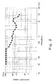
- Fig. 2 is a graph showing the relation between the directivity angle and frequency of the woofer 2 according to the present embodiment. In Fig. 2 , a horizontal axis denotes the frequency, and a vertical axis denotes the directivity angle. As shown in Fig. 2 , the directivity angle gradually decreases from about 250 Hz of the frequency of the woofer 2. Thus, the directivity angle of the woofer 2 tends to decrease as the frequency of the woofer 2 increases.
- the tweeter 3 is a cone speaker, and serves to emit sound waves in a high-pitched sound range.
- the speaker system 1 includes six tweeters 3, and all the tweeters 3 are attached to the tweeter frame 5.
- each tweeter 3 has a diameter of about 3.5 cm.
- six tweeters 3 are arranged in front of the woofer 2 in a line and a circular-arc formation. By a line array effect realized by arranging six tweeters 3 in a line, each tweeter 3 does not emit the sound wave spreading in a spherical shape, but the group of six tweeters 3 transmits a linear sound wave.
- a portion emitting a sound source can be regarded as one large sound source, and the center position of the sound wave spreading in a circular-arc shape from the group of the tweeters 3 can be moved backward.
- the center position of the sound wave spreading in the circular-arc shape from the group of the tweeters 3 and the center position of the sound wave spreading in the circular-arc shape from the woofer 2 can be made closer to each other.
- the sound wave emitted from the tweeter 3 and the sound wave emitted from the woofer 2 are less likely to interfere with each other not only in the front direction but also the directions except for the front direction in a flat plane including axes of two tweeter 3 arranged on both ends.
- the directivity angle of the group of the tweeters 3 can be adjusted.
- the axis of the tweeter 3 located on a more outer side among six tweeters 3 inclines more outwardly.
- an angle between the axes of two tweeters 3 located on both ends among six tweeters 3 is 40 degrees.
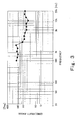
- Fig. 3 is a graph showing a relation between the directivity angle and frequency of the tweeter 3 according to the present embodiment.
- a horizontal axis denotes the frequency
- a vertical axis denotes the directivity angle.
- the value of the directivity angle is a value in the flat plane including the axes of two tweeters 3 arranged on both ends. As shown in Fig. 3 , as with the woofer 2, the directivity angle of the tweeter 3 tends to decrease as the frequency increases.
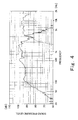
- Fig. 4 is a graph showing a relation between the frequency and sound pressure level of the tweeter 3 and a relation between the frequency and sound pressure level of the woofer 2.
- a horizontal axis denotes the frequency
- a vertical axis denotes the sound pressure level.
- a solid line denotes the woofer 2
- a broken line denotes the tweeter 3.
- a curved line of the woofer 2 and a curved line of the tweeter 3 intersect with each other in the vicinity of the frequency of 3 kHz. That is, the vicinity of 3 kHz is a crossover frequency.
- a sound signal from an audio device or the like is transmitted via a dividing network to the woofer and the tweeter.
- the crossover frequency is set in the dividing network.
- each of the directivity angle of the woofer 2 and the directivity angle of the tweeter 3 is about 50 degrees.
- inclination angles of the axes of six tweeters 3 are set such that the directivity angle of the group of the tweeters 3 is substantially the same as the directivity angle of the woofer 2.
- the directivity angle of the group of six tweeters 3 does not have to coincide with the directivity angle of the woofer 2 at the crossover frequency. To be specific, the above effects can be adequately obtained as long as the directivity angle of the group of six tweeters 3 is in a range from 90% to 110% of the directivity angle of the woofer 2 at the crossover frequency.
- Such setting of the directivity angle can be realized by setting the angle between the axes of two tweeters 3 arranged on both ends to be in a range from 70% to 90% of the directivity angle of the woofer 2 at the crossover frequency. In the present embodiment, the above setting is realized by setting the angle between the axes of two tweeters 3 arranged on both ends to be 40 degrees, i.e., 80% of 50 degrees which is the directivity angle of the woofer 2 at the crossover frequency.
- the enclosure 4 serves to fix the tweeter frame 5 to which the woofer 2 and the tweeter 3 are mainly attached.
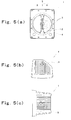
- Figs. 5 are diagrams showing the enclosure 4.
- Fig. 5(a) is a front view
- Fig. 5(b) is a top view
- Fig. 5(c) is a right side view.
- the enclosure 4 includes an inclined surface 9 on a rear side thereof. When the enclosure 4 is placed on a horizontal surface by using the inclined surface 9 as a bottom surface, the axis of the woofer 2 extends diagonally upwardly, and six tweeters 3 are arranged in a horizontal direction.
- the speaker system 1 can efficiently emit the sound wave when, for example, it is used as a front monitor for a MC (Master of Ceremonies).
- MC Master of Ceremonies
- the speaker system emits the sound wave which is less likely to attenuate in this region, it is extremely effective.
- the tweeter frame 5 serves to fix the tweeters 3. As shown in Fig. 1 , the tweeter frame 5 is joined to the enclosure 4 in the vicinity of a peripheral edge of the woofer 2. Moreover, the joined portions are upper and lower positions of the woofer 2. To be specific, the tweeter frame 5 is hanged between two opposed positions located in the vicinity of the peripheral edge of the woofer 2.
- the tweeter frame 5 is mainly constituted by a base portion 7 and side walls 8.
- the tweeters 3 are attached to the base portion 7.
- the width of the base portion 7 is substantially the same as the diameter of the opening of the tweeter 3, but both end portions connected to the enclosure 4 are wider to increase the strength.
- the base portion 7 has a circular-arc shape, and the center position of this circular arc is substantially the same as the center position of the sound wave spreading in the circular-arc shape from the woofer 2.
- the axis of the tweeter 3 intersects with the base portion 7 at right angle. With this configuration, the tweeter 3 can emit the sound wave along the propagation of the sound wave emitted from the woofer 2.
- the side wall 8 has a flare shape extending along a side end portion of the base portion 7 and spreading outwardly.
- the tweeter frame 5 can serve as a constant directivity horn. Therefore, the directivity can be controlled in not only a direction in which the tweeters 3 are arranged but also a direction perpendicular to the direction in which the tweeters 3 are arranged. Thus, the sound wave can be efficiently emitted.
- the base portion 7 and the side wall 8 are substantially the same in thickness as each other, and the thickness is about 7 mm.
- the rear cover 6 is a member covering rear portions of the tweeters 3. Moreover, the rear cover 6 is attached to the tweeter frame 5 by screws so as to sandwich the tweeters 3.
- Fig. 7 is a horizontal cross-sectional view of the tweeter 3 to which the rear cover 6 is attached. As shown in Fig. 7 , the rear cover 6 has a mountain-like shape whose sharp angle faces the woofer 2. Thus, by covering the rear portions of the tweeters 3 with the rear cover 6 having the mountain-like shape, the sound wave emitted from the woofer 2 is less likely to reflect on the rear portions of the tweeters 3. Therefore, it is possible to suppress interference between the sound wave directly emitted from the woofer 2 and the reflected sound wave.
- the speaker system 1 has explained the configuration of the speaker system 1 according to the present embodiment.
- the common 2-way speaker system system in which the woofer and the tweeter are not coaxially arranged
- the listeners often recognize that the positions of the sound sources, such as the tweeter and the woofer, are different from each other, and the sound is unnatural.
- the above unnatural sound is not emitted.
- the 2-way speaker system in which the woofer and the group of three or more tweeters are coaxially arranged as in the present invention has an advantage that the sound emitted for the listeners near the system is not unnatural, and in addition, it can emit the sound for only a specific listener by controlling the directivity. Therefore, the present invention can realize a speaker system especially suitable for the application shown in Fig. 6 .
- the present invention can provide a speaker system in which the woofer and the group of the tweeters are coaxially arranged, and the sound waves emitted from the woofer and the sound waves emitted from the tweeter are less likely to interfere with each other in at least one direction, and whose sound pressure frequency characteristics easily stabilize in at least one direction. Therefore, the present invention is useful in the technical field of the speaker system, especially in the technical field of the speaker system in which the woofer and the group of the tweeters are coaxially arranged.
Landscapes
- Health & Medical Sciences (AREA)
- Otolaryngology (AREA)
- Physics & Mathematics (AREA)
- Engineering & Computer Science (AREA)
- Acoustics & Sound (AREA)
- Signal Processing (AREA)
- Obtaining Desirable Characteristics In Audible-Bandwidth Transducers (AREA)
- Circuit For Audible Band Transducer (AREA)
- Fittings On The Vehicle Exterior For Carrying Loads, And Devices For Holding Or Mounting Articles (AREA)
Applications Claiming Priority (2)
| Application Number | Priority Date | Filing Date | Title |
|---|---|---|---|
| JP2006308086A JP4878989B2 (ja) | 2006-11-14 | 2006-11-14 | スピーカシステム |
| PCT/JP2007/071943 WO2008059802A1 (en) | 2006-11-14 | 2007-11-12 | Speaker system |
Publications (3)
| Publication Number | Publication Date |
|---|---|
| EP2096880A1 EP2096880A1 (en) | 2009-09-02 |
| EP2096880A4 EP2096880A4 (en) | 2011-05-04 |
| EP2096880B1 true EP2096880B1 (en) | 2013-09-25 |
Family
ID=39401610
Family Applications (1)
| Application Number | Title | Priority Date | Filing Date |
|---|---|---|---|
| EP07831673.4A Not-in-force EP2096880B1 (en) | 2006-11-14 | 2007-11-12 | Speaker system |
Country Status (7)
| Country | Link |
|---|---|
| US (1) | US8189823B2 (enExample) |
| EP (1) | EP2096880B1 (enExample) |
| JP (1) | JP4878989B2 (enExample) |
| KR (1) | KR101067386B1 (enExample) |
| CN (1) | CN101536539B (enExample) |
| CA (1) | CA2667861A1 (enExample) |
| WO (1) | WO2008059802A1 (enExample) |
Families Citing this family (19)
| Publication number | Priority date | Publication date | Assignee | Title |
|---|---|---|---|---|
| US8126180B2 (en) * | 2008-10-31 | 2012-02-28 | Bose Corporation | Dual configuration speaker |
| KR101681780B1 (ko) * | 2010-08-12 | 2016-12-01 | 엘지전자 주식회사 | 스피커 시스템 |
| JP2015525348A (ja) | 2012-06-14 | 2015-09-03 | ホアウェイ・デバイス・カンパニー・リミテッド | モバイルデバイスのための気圧の較正方法、較正デバイスおよびモバイルデバイス |
| KR101371229B1 (ko) * | 2013-04-23 | 2014-03-10 | 에스텍 주식회사 | 2웨이 스피커 |
| JP2015080137A (ja) * | 2013-10-18 | 2015-04-23 | 株式会社Jvcケンウッド | スピーカシステム |
| KR101515618B1 (ko) * | 2014-03-20 | 2015-04-28 | 김태형 | 래티스 타입 스피커, 및 이를 구비한 래티스 어레이 스피커 시스템 |
| US9860630B2 (en) | 2014-05-02 | 2018-01-02 | Core Brands, Llc | Vibration damping and mounting assembly for a loudspeaker |
| CN104038870A (zh) * | 2014-05-15 | 2014-09-10 | 浙江长兴家宝电子有限公司 | 一种多媒体音箱 |
| EP3205116B1 (en) * | 2014-10-10 | 2021-07-28 | Gde Engineering Pty Ltd | Method and apparatus for providing customised sound distributions |
| CN105282649B (zh) * | 2015-11-10 | 2019-02-22 | 广州杰士莱电子有限公司 | 一种基于多声源的音箱 |
| CN105959833B (zh) * | 2016-06-07 | 2019-02-19 | 东莞精恒电子有限公司 | 一种音箱结构 |
| US20180225049A1 (en) * | 2017-02-03 | 2018-08-09 | Sensors Unlimited, Inc. | Media recording systems |
| CN108966090B (zh) * | 2017-05-18 | 2022-05-24 | 哈曼国际工业有限公司 | 用于定向性和分散控制的扬声器系统和配置 |
| US10524042B2 (en) | 2017-06-27 | 2019-12-31 | Bose Corporation | Electro-acoustical transducer arrangements of a sound system |
| US10104761B1 (en) | 2017-06-27 | 2018-10-16 | Bose Corporation | Cooling techniques to improve thermal performance of electroacoustic device |
| US10306386B2 (en) | 2017-06-27 | 2019-05-28 | Bose Corporation | Portable speaker configurations |
| JP7200788B2 (ja) * | 2019-03-25 | 2023-01-10 | 株式会社Jvcケンウッド | スピーカシステム |
| CN110049390B (zh) * | 2019-04-24 | 2024-06-25 | 广州杰士莱电子有限公司 | 一种挂式音箱 |
| US20240056713A1 (en) * | 2022-08-12 | 2024-02-15 | Afco, Inc. | Speaker apparatus |
Citations (1)
| Publication number | Priority date | Publication date | Assignee | Title |
|---|---|---|---|---|
| US20040240697A1 (en) * | 2003-05-27 | 2004-12-02 | Keele D. Broadus | Constant-beamwidth loudspeaker array |
Family Cites Families (13)
| Publication number | Priority date | Publication date | Assignee | Title |
|---|---|---|---|---|
| SE387512B (sv) * | 1973-08-24 | 1976-09-06 | S Carlsson | Hogtalare for sterofonisk ljudatergivningsanleggning, samt av tva sadana hogtalare bestaende hogtalarpar |
| JPS5818381Y2 (ja) * | 1978-02-17 | 1983-04-14 | ソニー株式会社 | スピ−カ装置 |
| US4227051A (en) * | 1979-02-26 | 1980-10-07 | Thomas Wayne W | Loud speaker and enclosure system |
| JPS61187195A (ja) | 1985-02-15 | 1986-08-20 | Nec Corp | メモリリフレツシユ制御方式 |
| JPS61187195U (enExample) | 1985-05-14 | 1986-11-21 | ||
| US5548657A (en) | 1988-05-09 | 1996-08-20 | Kef Audio (Uk) Limited | Compound loudspeaker drive unit |
| JPH02177699A (ja) * | 1988-12-28 | 1990-07-10 | Pioneer Electron Corp | スピーカ |
| JP2836279B2 (ja) | 1991-04-12 | 1998-12-14 | 三菱マテリアル株式会社 | インジェクタ |
| JP2582892Y2 (ja) * | 1992-02-12 | 1998-10-15 | 株式会社ケンウッド | 無指向性スピーカ |
| WO1998007297A1 (en) * | 1996-08-09 | 1998-02-19 | Blodget Clifford L | Line array |
| US7302061B2 (en) * | 2001-11-21 | 2007-11-27 | Ksc Industries Incorporated | Dual-tweeter loudspeaker |
| JP4073258B2 (ja) | 2002-06-12 | 2008-04-09 | 株式会社ケンウッド | 音出力装置 |
| JP2004165917A (ja) | 2002-11-12 | 2004-06-10 | Sony Corp | 複合型スピーカ装置 |
-
2006
- 2006-11-14 JP JP2006308086A patent/JP4878989B2/ja active Active
-
2007
- 2007-11-12 WO PCT/JP2007/071943 patent/WO2008059802A1/ja not_active Ceased
- 2007-11-12 CA CA002667861A patent/CA2667861A1/en not_active Abandoned
- 2007-11-12 EP EP07831673.4A patent/EP2096880B1/en not_active Not-in-force
- 2007-11-12 US US12/514,569 patent/US8189823B2/en not_active Expired - Fee Related
- 2007-11-12 KR KR1020097007208A patent/KR101067386B1/ko not_active Expired - Fee Related
- 2007-11-12 CN CN200780041948.XA patent/CN101536539B/zh not_active Expired - Fee Related
Patent Citations (1)
| Publication number | Priority date | Publication date | Assignee | Title |
|---|---|---|---|---|
| US20040240697A1 (en) * | 2003-05-27 | 2004-12-02 | Keele D. Broadus | Constant-beamwidth loudspeaker array |
Also Published As
| Publication number | Publication date |
|---|---|
| KR101067386B1 (ko) | 2011-09-26 |
| KR20090094219A (ko) | 2009-09-04 |
| WO2008059802A1 (en) | 2008-05-22 |
| EP2096880A1 (en) | 2009-09-02 |
| JP2008124903A (ja) | 2008-05-29 |
| CN101536539A (zh) | 2009-09-16 |
| JP4878989B2 (ja) | 2012-02-15 |
| EP2096880A4 (en) | 2011-05-04 |
| US20100027827A1 (en) | 2010-02-04 |
| US8189823B2 (en) | 2012-05-29 |
| CA2667861A1 (en) | 2008-05-22 |
| CN101536539B (zh) | 2013-01-30 |
Similar Documents
| Publication | Publication Date | Title |
|---|---|---|
| EP2096880B1 (en) | Speaker system | |
| CA2477928C (en) | Loudspeaker with shaped sound field | |
| US5526456A (en) | Multiple-driver single horn loud speaker | |
| US10524042B2 (en) | Electro-acoustical transducer arrangements of a sound system | |
| EP1460880A2 (en) | Loudspeaker array | |
| JP3732007B2 (ja) | ホーンスピーカ | |
| US20170325019A1 (en) | Waveguide for a height channel in a speaker | |
| JP2018527808A (ja) | サウンドバー | |
| WO1999011098A1 (en) | Down-fill speaker for large scale sound reproduction system | |
| EP2814262B1 (en) | Loudspeaker with a wave guide | |
| EP3466108B1 (en) | Baffle for line array loudspeaker | |
| EP2356824B1 (en) | An audio speaker arrangement | |
| EP3018915B1 (en) | Directional loudspeaker | |
| US6820718B2 (en) | Acoustic reproduction device with improved directional characteristics | |
| US20220353607A1 (en) | Speaker system with asymmetrical coverage horn | |
| CN113574910B (zh) | 高置声道扬声器及相关方法和系统 | |
| CN102714768A (zh) | 平面扬声器 | |
| US4437541A (en) | Controlled dispersion speaker configuration | |
| US12200433B2 (en) | Line source loudspeaker device | |
| TW201603591A (zh) | 音響波導管及使用其之條形音箱 | |
| JPH0479500A (ja) | スピーカシステム | |
| HK40017054A (en) | Electro-acoustical transducer arrangements of a sound system | |
| WO2011042019A1 (en) | Dipole loudspeaker with diffuse rear radiation |
Legal Events
| Date | Code | Title | Description |
|---|---|---|---|
| PUAI | Public reference made under article 153(3) epc to a published international application that has entered the european phase |
Free format text: ORIGINAL CODE: 0009012 |
|
| 17P | Request for examination filed |
Effective date: 20090612 |
|
| AK | Designated contracting states |
Kind code of ref document: A1 Designated state(s): AT BE BG CH CY CZ DE DK EE ES FI FR GB GR HU IE IS IT LI LT LU LV MC MT NL PL PT RO SE SI SK TR |
|
| DAX | Request for extension of the european patent (deleted) | ||
| A4 | Supplementary search report drawn up and despatched |
Effective date: 20110331 |
|
| RIC1 | Information provided on ipc code assigned before grant |
Ipc: H04R 1/40 20060101ALN20110325BHEP Ipc: H04R 1/24 20060101AFI20110325BHEP |
|
| 17Q | First examination report despatched |
Effective date: 20111227 |
|
| REG | Reference to a national code |
Ref country code: DE Ref legal event code: R079 Ref document number: 602007033063 Country of ref document: DE Free format text: PREVIOUS MAIN CLASS: H04R0001320000 Ipc: H04R0001240000 |
|
| GRAP | Despatch of communication of intention to grant a patent |
Free format text: ORIGINAL CODE: EPIDOSNIGR1 |
|
| RIC1 | Information provided on ipc code assigned before grant |
Ipc: H04R 1/40 20060101ALN20130220BHEP Ipc: H04R 1/24 20060101AFI20130220BHEP |
|
| RIC1 | Information provided on ipc code assigned before grant |
Ipc: H04R 1/40 20060101ALN20130226BHEP Ipc: H04R 1/24 20060101AFI20130226BHEP |
|
| GRAS | Grant fee paid |
Free format text: ORIGINAL CODE: EPIDOSNIGR3 |
|
| GRAA | (expected) grant |
Free format text: ORIGINAL CODE: 0009210 |
|
| AK | Designated contracting states |
Kind code of ref document: B1 Designated state(s): AT BE BG CH CY CZ DE DK EE ES FI FR GB GR HU IE IS IT LI LT LU LV MC MT NL PL PT RO SE SI SK TR |
|
| REG | Reference to a national code |
Ref country code: GB Ref legal event code: FG4D |
|
| REG | Reference to a national code |
Ref country code: CH Ref legal event code: EP |
|
| REG | Reference to a national code |
Ref country code: AT Ref legal event code: REF Ref document number: 634109 Country of ref document: AT Kind code of ref document: T Effective date: 20131015 |
|
| REG | Reference to a national code |
Ref country code: IE Ref legal event code: FG4D |
|
| REG | Reference to a national code |
Ref country code: DE Ref legal event code: R096 Ref document number: 602007033063 Country of ref document: DE Effective date: 20131121 |
|
| PG25 | Lapsed in a contracting state [announced via postgrant information from national office to epo] |
Ref country code: LT Free format text: LAPSE BECAUSE OF FAILURE TO SUBMIT A TRANSLATION OF THE DESCRIPTION OR TO PAY THE FEE WITHIN THE PRESCRIBED TIME-LIMIT Effective date: 20130925 Ref country code: SE Free format text: LAPSE BECAUSE OF FAILURE TO SUBMIT A TRANSLATION OF THE DESCRIPTION OR TO PAY THE FEE WITHIN THE PRESCRIBED TIME-LIMIT Effective date: 20130925 |
|
| REG | Reference to a national code |
Ref country code: AT Ref legal event code: MK05 Ref document number: 634109 Country of ref document: AT Kind code of ref document: T Effective date: 20130925 |
|
| REG | Reference to a national code |
Ref country code: NL Ref legal event code: VDEP Effective date: 20130925 |
|
| REG | Reference to a national code |
Ref country code: LT Ref legal event code: MG4D |
|
| PG25 | Lapsed in a contracting state [announced via postgrant information from national office to epo] |
Ref country code: LV Free format text: LAPSE BECAUSE OF FAILURE TO SUBMIT A TRANSLATION OF THE DESCRIPTION OR TO PAY THE FEE WITHIN THE PRESCRIBED TIME-LIMIT Effective date: 20130925 Ref country code: GR Free format text: LAPSE BECAUSE OF FAILURE TO SUBMIT A TRANSLATION OF THE DESCRIPTION OR TO PAY THE FEE WITHIN THE PRESCRIBED TIME-LIMIT Effective date: 20131226 Ref country code: SI Free format text: LAPSE BECAUSE OF FAILURE TO SUBMIT A TRANSLATION OF THE DESCRIPTION OR TO PAY THE FEE WITHIN THE PRESCRIBED TIME-LIMIT Effective date: 20130925 Ref country code: FI Free format text: LAPSE BECAUSE OF FAILURE TO SUBMIT A TRANSLATION OF THE DESCRIPTION OR TO PAY THE FEE WITHIN THE PRESCRIBED TIME-LIMIT Effective date: 20130925 |
|
| PG25 | Lapsed in a contracting state [announced via postgrant information from national office to epo] |
Ref country code: BE Free format text: LAPSE BECAUSE OF FAILURE TO SUBMIT A TRANSLATION OF THE DESCRIPTION OR TO PAY THE FEE WITHIN THE PRESCRIBED TIME-LIMIT Effective date: 20130925 |
|
| PG25 | Lapsed in a contracting state [announced via postgrant information from national office to epo] |
Ref country code: EE Free format text: LAPSE BECAUSE OF FAILURE TO SUBMIT A TRANSLATION OF THE DESCRIPTION OR TO PAY THE FEE WITHIN THE PRESCRIBED TIME-LIMIT Effective date: 20130925 Ref country code: CZ Free format text: LAPSE BECAUSE OF FAILURE TO SUBMIT A TRANSLATION OF THE DESCRIPTION OR TO PAY THE FEE WITHIN THE PRESCRIBED TIME-LIMIT Effective date: 20130925 Ref country code: RO Free format text: LAPSE BECAUSE OF FAILURE TO SUBMIT A TRANSLATION OF THE DESCRIPTION OR TO PAY THE FEE WITHIN THE PRESCRIBED TIME-LIMIT Effective date: 20130925 Ref country code: NL Free format text: LAPSE BECAUSE OF FAILURE TO SUBMIT A TRANSLATION OF THE DESCRIPTION OR TO PAY THE FEE WITHIN THE PRESCRIBED TIME-LIMIT Effective date: 20130925 Ref country code: SK Free format text: LAPSE BECAUSE OF FAILURE TO SUBMIT A TRANSLATION OF THE DESCRIPTION OR TO PAY THE FEE WITHIN THE PRESCRIBED TIME-LIMIT Effective date: 20130925 Ref country code: IS Free format text: LAPSE BECAUSE OF FAILURE TO SUBMIT A TRANSLATION OF THE DESCRIPTION OR TO PAY THE FEE WITHIN THE PRESCRIBED TIME-LIMIT Effective date: 20140125 |
|
| PG25 | Lapsed in a contracting state [announced via postgrant information from national office to epo] |
Ref country code: AT Free format text: LAPSE BECAUSE OF FAILURE TO SUBMIT A TRANSLATION OF THE DESCRIPTION OR TO PAY THE FEE WITHIN THE PRESCRIBED TIME-LIMIT Effective date: 20130925 Ref country code: CY Free format text: LAPSE BECAUSE OF FAILURE TO SUBMIT A TRANSLATION OF THE DESCRIPTION OR TO PAY THE FEE WITHIN THE PRESCRIBED TIME-LIMIT Effective date: 20130925 Ref country code: PL Free format text: LAPSE BECAUSE OF FAILURE TO SUBMIT A TRANSLATION OF THE DESCRIPTION OR TO PAY THE FEE WITHIN THE PRESCRIBED TIME-LIMIT Effective date: 20130925 Ref country code: ES Free format text: LAPSE BECAUSE OF FAILURE TO SUBMIT A TRANSLATION OF THE DESCRIPTION OR TO PAY THE FEE WITHIN THE PRESCRIBED TIME-LIMIT Effective date: 20130925 |
|
| REG | Reference to a national code |
Ref country code: DE Ref legal event code: R097 Ref document number: 602007033063 Country of ref document: DE |
|
| PG25 | Lapsed in a contracting state [announced via postgrant information from national office to epo] |
Ref country code: PT Free format text: LAPSE BECAUSE OF FAILURE TO SUBMIT A TRANSLATION OF THE DESCRIPTION OR TO PAY THE FEE WITHIN THE PRESCRIBED TIME-LIMIT Effective date: 20140127 |
|
| REG | Reference to a national code |
Ref country code: CH Ref legal event code: PL |
|
| PG25 | Lapsed in a contracting state [announced via postgrant information from national office to epo] |
Ref country code: CH Free format text: LAPSE BECAUSE OF NON-PAYMENT OF DUE FEES Effective date: 20131130 Ref country code: LI Free format text: LAPSE BECAUSE OF NON-PAYMENT OF DUE FEES Effective date: 20131130 Ref country code: MC Free format text: LAPSE BECAUSE OF FAILURE TO SUBMIT A TRANSLATION OF THE DESCRIPTION OR TO PAY THE FEE WITHIN THE PRESCRIBED TIME-LIMIT Effective date: 20130925 |
|
| PLBE | No opposition filed within time limit |
Free format text: ORIGINAL CODE: 0009261 |
|
| STAA | Information on the status of an ep patent application or granted ep patent |
Free format text: STATUS: NO OPPOSITION FILED WITHIN TIME LIMIT |
|
| REG | Reference to a national code |
Ref country code: IE Ref legal event code: MM4A |
|
| PG25 | Lapsed in a contracting state [announced via postgrant information from national office to epo] |
Ref country code: IT Free format text: LAPSE BECAUSE OF FAILURE TO SUBMIT A TRANSLATION OF THE DESCRIPTION OR TO PAY THE FEE WITHIN THE PRESCRIBED TIME-LIMIT Effective date: 20130925 |
|
| 26N | No opposition filed |
Effective date: 20140626 |
|
| PG25 | Lapsed in a contracting state [announced via postgrant information from national office to epo] |
Ref country code: DK Free format text: LAPSE BECAUSE OF FAILURE TO SUBMIT A TRANSLATION OF THE DESCRIPTION OR TO PAY THE FEE WITHIN THE PRESCRIBED TIME-LIMIT Effective date: 20130925 |
|
| REG | Reference to a national code |
Ref country code: DE Ref legal event code: R097 Ref document number: 602007033063 Country of ref document: DE Effective date: 20140626 |
|
| PG25 | Lapsed in a contracting state [announced via postgrant information from national office to epo] |
Ref country code: IE Free format text: LAPSE BECAUSE OF NON-PAYMENT OF DUE FEES Effective date: 20131112 |
|
| PG25 | Lapsed in a contracting state [announced via postgrant information from national office to epo] |
Ref country code: TR Free format text: LAPSE BECAUSE OF FAILURE TO SUBMIT A TRANSLATION OF THE DESCRIPTION OR TO PAY THE FEE WITHIN THE PRESCRIBED TIME-LIMIT Effective date: 20130925 |
|
| PG25 | Lapsed in a contracting state [announced via postgrant information from national office to epo] |
Ref country code: LU Free format text: LAPSE BECAUSE OF NON-PAYMENT OF DUE FEES Effective date: 20131112 Ref country code: HU Free format text: LAPSE BECAUSE OF FAILURE TO SUBMIT A TRANSLATION OF THE DESCRIPTION OR TO PAY THE FEE WITHIN THE PRESCRIBED TIME-LIMIT; INVALID AB INITIO Effective date: 20071112 Ref country code: BG Free format text: LAPSE BECAUSE OF FAILURE TO SUBMIT A TRANSLATION OF THE DESCRIPTION OR TO PAY THE FEE WITHIN THE PRESCRIBED TIME-LIMIT Effective date: 20130925 |
|
| PG25 | Lapsed in a contracting state [announced via postgrant information from national office to epo] |
Ref country code: MT Free format text: LAPSE BECAUSE OF FAILURE TO SUBMIT A TRANSLATION OF THE DESCRIPTION OR TO PAY THE FEE WITHIN THE PRESCRIBED TIME-LIMIT Effective date: 20130925 |
|
| REG | Reference to a national code |
Ref country code: FR Ref legal event code: PLFP Year of fee payment: 9 |
|
| PGFP | Annual fee paid to national office [announced via postgrant information from national office to epo] |
Ref country code: GB Payment date: 20151111 Year of fee payment: 9 |
|
| PGFP | Annual fee paid to national office [announced via postgrant information from national office to epo] |
Ref country code: FR Payment date: 20151008 Year of fee payment: 9 |
|
| GBPC | Gb: european patent ceased through non-payment of renewal fee |
Effective date: 20161112 |
|
| REG | Reference to a national code |
Ref country code: FR Ref legal event code: ST Effective date: 20170731 |
|
| PG25 | Lapsed in a contracting state [announced via postgrant information from national office to epo] |
Ref country code: FR Free format text: LAPSE BECAUSE OF NON-PAYMENT OF DUE FEES Effective date: 20161130 |
|
| PG25 | Lapsed in a contracting state [announced via postgrant information from national office to epo] |
Ref country code: GB Free format text: LAPSE BECAUSE OF NON-PAYMENT OF DUE FEES Effective date: 20161112 |
|
| PGFP | Annual fee paid to national office [announced via postgrant information from national office to epo] |
Ref country code: DE Payment date: 20220930 Year of fee payment: 16 |
|
| REG | Reference to a national code |
Ref country code: DE Ref legal event code: R119 Ref document number: 602007033063 Country of ref document: DE |
|
| PG25 | Lapsed in a contracting state [announced via postgrant information from national office to epo] |
Ref country code: DE Free format text: LAPSE BECAUSE OF NON-PAYMENT OF DUE FEES Effective date: 20240601 |
|
| PG25 | Lapsed in a contracting state [announced via postgrant information from national office to epo] |
Ref country code: DE Free format text: LAPSE BECAUSE OF NON-PAYMENT OF DUE FEES Effective date: 20240601 |