EP2095371B1 - Vorrichtung zum untersatützen des be- oder entladens eines kerns eines druckwasserreaktors - Google Patents
Vorrichtung zum untersatützen des be- oder entladens eines kerns eines druckwasserreaktors Download PDFInfo
- Publication number
- EP2095371B1 EP2095371B1 EP07856213A EP07856213A EP2095371B1 EP 2095371 B1 EP2095371 B1 EP 2095371B1 EP 07856213 A EP07856213 A EP 07856213A EP 07856213 A EP07856213 A EP 07856213A EP 2095371 B1 EP2095371 B1 EP 2095371B1
- Authority
- EP
- European Patent Office
- Prior art keywords
- fuel element
- fuel
- support shaft
- core
- support
- Prior art date
- Legal status (The legal status is an assumption and is not a legal conclusion. Google has not performed a legal analysis and makes no representation as to the accuracy of the status listed.)
- Active
Links
- XLYOFNOQVPJJNP-UHFFFAOYSA-N water Substances O XLYOFNOQVPJJNP-UHFFFAOYSA-N 0.000 title claims description 11
- 239000000446 fuel Substances 0.000 claims description 93
- 230000000712 assembly Effects 0.000 description 11
- 238000000429 assembly Methods 0.000 description 11
- 230000005484 gravity Effects 0.000 description 6
- 239000000498 cooling water Substances 0.000 description 2
- 238000007654 immersion Methods 0.000 description 2
- 238000004873 anchoring Methods 0.000 description 1
- 230000005540 biological transmission Effects 0.000 description 1
- 238000005253 cladding Methods 0.000 description 1
- 238000012937 correction Methods 0.000 description 1
- 238000003780 insertion Methods 0.000 description 1
- 230000037431 insertion Effects 0.000 description 1
- 238000007689 inspection Methods 0.000 description 1
- 238000009434 installation Methods 0.000 description 1
- 230000003993 interaction Effects 0.000 description 1
- 230000005855 radiation Effects 0.000 description 1
- 238000011084 recovery Methods 0.000 description 1
- 230000008439 repair process Effects 0.000 description 1
Images

Classifications
-
- G—PHYSICS
- G21—NUCLEAR PHYSICS; NUCLEAR ENGINEERING
- G21C—NUCLEAR REACTORS
- G21C19/00—Arrangements for treating, for handling, or for facilitating the handling of, fuel or other materials which are used within the reactor, e.g. within its pressure vessel
- G21C19/16—Articulated or telescopic chutes or tubes for connection to channels in the reactor core
-
- Y—GENERAL TAGGING OF NEW TECHNOLOGICAL DEVELOPMENTS; GENERAL TAGGING OF CROSS-SECTIONAL TECHNOLOGIES SPANNING OVER SEVERAL SECTIONS OF THE IPC; TECHNICAL SUBJECTS COVERED BY FORMER USPC CROSS-REFERENCE ART COLLECTIONS [XRACs] AND DIGESTS
- Y02—TECHNOLOGIES OR APPLICATIONS FOR MITIGATION OR ADAPTATION AGAINST CLIMATE CHANGE
- Y02E—REDUCTION OF GREENHOUSE GAS [GHG] EMISSIONS, RELATED TO ENERGY GENERATION, TRANSMISSION OR DISTRIBUTION
- Y02E30/00—Energy generation of nuclear origin
- Y02E30/30—Nuclear fission reactors
Definitions
- the invention relates to a device for assisting the loading or unloading of a core of a pressurized water reactor.
- fuel element loading machines For loading and unloading a core of a pressurized water reactor so-called fuel element loading machines are used, which must be approached exactly in the respective Bennelementposition and centered there must be aligned to the fuel assembly.
- Bent or twisted fuel assemblies create problems centering the fuel assembly loading machine.
- fuel assembly loading machines are centering the centering of a centering bell of the fuel assembly loading machine introduced in center holes of the adjacent fuel elements. If these are offset or twisted, centering of the fuel assembly loading machine is not possible.
- these deflections can take on a degree that is a change of fuel assemblies during loading or unloading of the core, as strongly bent fuel assemblies can not be easily pulled out of the core and invited into the core.
- a fuel assembly machine which has a tubular centering device at its lower end.
- the centering device is conically shaped at its lower edge and slides along the fuel elements which are adjacent to the fuel element position to be loaded or unloaded, pushes them apart and in this way is positioned exactly centered in the fuel assembly.
- a safe centering is only possible with this known fuel assembly loading machine when the fuel assembly surrounding fuel elements are arranged symmetrically about this.
- the invention is an object of the invention to provide a device for supporting the loading and unloading of a core of a pressurized water reactor, with the change of a fuel assembly is facilitated.
- the device comprises a submerged with a plurality of Antiebsaggregaten underwater maneuverable submersible, on which at least one aus suiter support arm is arranged, which is against a fuel element of Kerns, which is adjacent to a fuel element position to be unloaded or loaded, in an upper region under exercise of acting transversely to the axial direction of the fuel assembly force is at least indirectly adjustable.
- this fuel element is either pushed away or bent away from the fuel element position to be loaded or unloaded or used closer to this fuel element position.
- the use of a submersible vehicle also eliminates the costly installation of a manipulator and obstruction of the use of the fuel assembly loading machine is largely avoided.
- At least indirectly in the sense of the present invention means that the support arm acts either directly (when pushing away) or indirectly to the adjacent fuel element when it is employed on a fuel element adjacent to this fuel element, via which the force is transmitted to the adjacent fuel assembly.
- the expositable support arm comprises at its free end an insertable from above into a head frame of the fuel element pin which applies when issuing or retracting the support arm while exerting force on an inner surface of the head frame, in particular a pushing away a bent towards the loading or unloading fuel assembly position Fuel element facilitates, as it is also close to each other Fuel elements is easily possible to introduce the mandrel in the head frame.
- the submersible vehicle comprises at least one support element for receiving the force exerted by the support arm on the fuel assembly. In this way, a secure anchoring of the submersible vehicle and thus an effective power transmission is ensured on the fuel assembly.
- the at least one support element is formed by a mandrel, which in a defined on the head frame of a fuel assembly and in the installed state of the fuel assembly vertical, i. in a longitudinal direction of the fuel element extending center hole is inserted, which is adjacent to the fuel assembly and the fuel element or to which the or the support arms are adjustable.
- a mandrel which in a defined on the head frame of a fuel assembly and in the installed state of the fuel assembly vertical, i. in a longitudinal direction of the fuel element extending center hole is inserted, which is adjacent to the fuel assembly and the fuel element or to which the or the support arms are adjustable.
- the submersible on a U-shaped buoyancy body In a further particularly advantageous embodiment of the invention, the submersible on a U-shaped buoyancy body. In this way, it is possible to move the center of gravity of the buoyancy force in the vicinity of the center of gravity of the submersible, without hindering the start of the fuel assembly loading machine, since this then between the legs of the buoyant body can be driven down into the fuel assembly position.
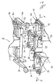
- Fig. 1 is provided as a device a submersible vehicle 2, which is freely maneuverable under water.
- the submersible vehicle 2 comprises a U-shaped buoyancy body 4, whose buoyancy under water at least approximately compensates for the weight of the submersible vehicle 2.
- On the submersible 2 a plurality of drive units 6 are arranged, with which the submersible vehicle 2 is freely positionable under water with respect to its location and in terms of its spatial orientation.
- the other structural units of the submersible vehicle 2 and the U-shaped buoyancy body 4 are designed and arranged so that the plane spanned by his legs 10, 12 and its base 14 is oriented at least approximately horizontally when the submersible vehicle 2 with switched off drive units 6 in Floating state is, so that at most slight corrections are required for accurate horizontal alignment, which are made by driving the drive units 6.
- the center of gravity of the displaced volume and the center of gravity lie on a straight line which runs perpendicular to the plane defined by the buoyancy body 4.
- a gripper or support plate 8 is fixed, which connects the two legs 10,12 each other and with the base 14.
- a column 16 at the end remote from the support plate 8 a support plate 18 is arranged.
- the center of gravity of the submersible vehicle 2 is located outside of the plane defined by the U-shaped drive body 4 on the side facing the support plate 18, so that these are stationary, i. in the stable floating state (buoyancy ⁇ gravity) is located below the buoyant body 4.
- hydraulic cylinders 20 are arranged on both sides of the column, of which in the perspective view of the figure only the hydraulic cylinder 20 located on one side of the column 16 are visible.
- a support arm 22,24 is fixed in each case by means of these hydraulic cylinders 20 in the direction of the double arrows 26 perpendicular to the longitudinal axis of the column 16 and parallel to the base 14 and the plane defined by the U-shaped buoyancy body 4 plane can be retracted or retracted.
- the support arms 22,24 extend parallel to the legs 10,12 of the buoyancy body 4, ie transversely to the Ausstellraum, and project beyond the support plate 18, so that the free end of the support arms 22,24 facing end side of the support plate 18 together with the Supporting arms 22,24 define a cross-sectionally U-shaped, built-in gap 28.
- This built-in space 28 extends over the entire height of the submersible vehicle 2, that is, over the extent thereof perpendicular to the plane defined by the U-shaped buoyancy body 4.
- two mandrels 30 are fixed, which extend parallel to the pillar 16 or perpendicular to the plane spanned by the buoyancy body 4.
- a pin or pins 32,34 At the free end of the support arms 22,24 is in each case a pin or pins 32,34. These pins 32,34 extend in the same direction as the mandrels 30 and point away from the buoyancy body 4.
- a plurality of light sources 40 and a plurality of underwater cameras 42 are also arranged on the buoyant body 4.
- the support plate 8 also includes a plurality of openings 8a, b which serve to dock and center a single gripper of the fueling machine when recovery of the submersible vehicle 2 is required in the event of failure of the electronics or individual units.
- the immersion vehicle 8 shown only in a section is in a working position above the core of a pressurized water reactor, of which only the upper area for three fuel elements 50 is shown, which surrounds a fuel element position 52 empty in the exemplary embodiment.
- the head frames 54 of the fuel assemblies 50 are visible.
- the head frames 54 have at their upper end sides in the corners each centering holes 56.
- the mandrels 30 are retracted in the working position of the submersible vehicle 2, the dive vehicle in this way fix transverse to the axial direction 57 of the fuel assemblies 50.
- the mandrels 30 have for this purpose an insertion bevel and are mounted on the support plate 18 at a distance corresponding to the distance between two centering holes 56.
- the support arms 22, 24 fixed to two pistons 60 are now extended so that the fuel rods 50, which are located opposite one another in the position adjacent to the fuel element position 52-in the example formed in the interior space formed by the head frame 54-protrude into the interior each on an inner surface of the head frame 54, ie abut in an upper region of the fuel assemblies 50.
- a force F is thus exerted on the fuel elements 50 arranged opposite one another on both sides of the fuel element position, in each case in the direction of the arrows, which forces the fuel assemblies 50 apart so that the distance between these two fuel elements 50 is increased. This increase in distance is maximum in the head frame 54.
- the forces F exerted on the two opposing fuel elements 50 are oppositely directed and at least approximately equal, so that the force to be absorbed by the fuel assembly 50 into which the mandrels 30 are inserted at least approximately disappears to ensure that only the two opposing ones are present fuel 50 are pushed away from each other.
- the mandrels 30 inserted into the central fuel assembly 50 serve as additional support members which receive the net force exerted on the support arms 22, 24 if the forces F are not equal in magnitude.
- the directions in which the forces F are exerted i. in which the available gap is to be increased, the unloading is followed by how the generally c-bowed deflection of a fuel element 50 located in this fuel assembly position 52 or, in the case of loading, also with what orientation a used throughbeam fuel element 50 is oriented this fuel element position 52 is to be used.
- a hydraulically or electromotively driven pivoting movement can also be provided.
- an electric motor driven pivoting movement eliminates the entrainment of hydraulic lines.
- an emergency release is provided, which releases an additional bearing clearance in the pivot bearing when clamping the pins 32,34, so that the pins 32,34 can be excavated from the centering holes 56.
Landscapes
- Physics & Mathematics (AREA)
- Engineering & Computer Science (AREA)
- Plasma & Fusion (AREA)
- General Engineering & Computer Science (AREA)
- High Energy & Nuclear Physics (AREA)
- Cooling, Air Intake And Gas Exhaust, And Fuel Tank Arrangements In Propulsion Units (AREA)
- Monitoring And Testing Of Nuclear Reactors (AREA)
- Automatic Cycles, And Cycles In General (AREA)
- Fuel-Injection Apparatus (AREA)
Description
- Die Erfindung bezieht sich auf eine Vorrichtung zum Unterstützen des Be- oder Entladens eines Kerns eines Druckwasserreaktors.
- Zum Be- und Entladen eines Kerns eines Druckwasserreaktors werden sogenannte Brennelementlademaschinen verwendet, die genau in die jeweilige Bennelementposition angefahren und dort zentriert zum Brennelement ausgerichtet werden müssen.
- Aus zahlreichen Inspektionsresultaten ist es bekannt, dass sich die Brennelemente eines Druckwasserreaktors im Laufe ihrer Einsatzdauer in Abhängigkeit von ihrer Position im Kern plastisch, d. h. dauerhaft verbiegen oder verdrehen. Diese Durchbiegungen können verschiedene Ursachen haben, beispielsweise eine Anisotropie in der thermischen Ausdehnung oder ein durch radioaktive Strahlung induziertes Längenwachstum der Brennstabhüllrohre oder der Steuerstabführungsrohre. Als wesentliche Gründe für diese Durchbiegung werden jedoch vor allen Dingen eine Wechselwirkung zwischen dem strömenden Kühlwasser und dem Brennelement sowie Inhomogenitäten beim Ein- und Ausströmen des Kühlwassers in bzw. aus dem Kern vermutet.
- Durch verbogene oder verdrehte Brennelemente entstehen Probleme beim Zentrieren der Brennelementlademaschine. Bei heute üblichen Brennelementlademaschinen werden zu deren Zentrierung die Zentrierstifte einer Zentrierglocke der Brennelementlademaschine in Zentrierbohrungen der benachbarten Brennelemente eingeführt. Sind diese versetzt oder verdreht, ist ein Zentrieren der Brennelementlademaschine nicht möglich. Darüber hinaus können diese Durchbiegungen ein Ausmaß annehmen, das einen Wechsel der Brennelemente beim Be- oder Entladen des Kerns wird, da stark durchgebogene Brennelemente nicht mehr ohne weiteres aus dem Kern herausgezogen und in den Kern eingeladen werden können.
- Aus der
DE 1 614 459 B ist eine Brennelementlademaschine bekannt, die an ihrem unterem Ende eine rohrförmige Zentriereinrichtung aufweist. Die Zentriereinrichtung ist an ihrem unteren Rand konisch geformt und gleitet an den Brennelementen entlang, die der zu be- oder entladenen Brennelementposition benachbart sind, drückt diese auseinander und wird auf diese Weise exakt mittig in dem Brennelement positioniert. Eine sichere Zentrierung ist mit dieser bekannten Brennelementlademaschine nur dann möglich, wenn die Brennelementposition umgebende Brennelemente symmetrisch um diese angeordnet sind. - Aus den Patentschriften
EP 1 411 528 A undWO 2004 102 584 A sind Richtvorrichtungen bekannt, mit denen die einer zu beladenden Brennelementposition benachbarten Brennelemente derartig verformt werden, dass diese das anschließende Einbringen eines Brennelementes in die zu beladende Position nicht mehr behindern. Aus derUS 2004 196 949 A1 ist ein mit einer Mehrzahl von Antriebsaggregaten frei manövrierbares Tauchfahrzeug für Reparaturen im Reaktorkernbereich bekannt. - Der Erfindung liegt nun die Aufgabe zugrunde, eine Vorrichtung zum Unterstützen des Be- und Entladens eines Kerns eines Druckwasserreaktors anzugeben, mit dem der Wechsel eines Brennelements erleichtert ist.
- Die genannte Aufgabe wird gemäß der Erfindung gelöst mit einer Vorrichtung mit den Merkmalen des Patentanspruches 1. Gemäß diesen Merkmalen umfasst die Vorrichtung ein mit einer Mehrzahl von Antiebsaggregaten unter Wasser frei manövrierbares Tauchfahrzeug, an dem zumindest ein ausstellbarer Tragarm angeordnet ist, der gegen ein Brennelement des Kerns, das einer zu entladenden oder beladenden Brennelementposition benachbart ist, in einem oberen Bereich unter Ausübung einer quer zur Axialrichtung des Brennelementes wirkenden Kraft zumindest mittelbar anstellbar ist.
- Durch diese Maßnahme wird dieses Brennelement von der zu beladenden oder entladenden Brennelementposition entweder weggedrückt oder weggebogen oder näher an diese Brennelementposition herangezogen. In der Regel ist es aber erforderlich, das Brennelement mit einer von der Brennelementposition weg gerichteten Kraft wegzubiegen, so dass ein vergrößerter Freiraum entsteht, der es ermöglicht, ein durchgebogenes Brennelement aus dieser Position zu entnehmen oder in diese Position einzubringen oder ein nicht durchgebogenes Brennelement in eine von durchgebogenen Brennelementen umgebene Brennelementposition einzusetzen. Durch die Verwendung eines Tauchfahrzeugs entfällt außerdem die aufwändige Installation eines Manipulators und eine Behinderung des Einsatzes der BrennelementLademaschine ist weitgehend vermieden.
- Zumindest mittelbar im Sinne der vorliegenden Erfindung heißt, dass der Tragarm entweder unmittelbar (beim Wegdrücken) oder mittelbar auf das benachbarte Brennelement wirkt, wenn er an ein diesem Brennelement benachbartes Brennelement angestellt wird, über das die Kraft auf das benachbarte Brennelement übertragen wird.
- Wenn der austellbare Tragarm an seinem freien Ende einen von oben in einen Kopfrahmen des Brennelements einführbaren Zapfen umfasst, der sich beim Ausstellen oder Einfahren des Tragarms unter Ausübung der Kraft an eine Innenfläche des Kopfrahmens anlegt, ist insbesondere ein Wegdrücken eines zur beladenden oder entladenden Brennelementposition hingebogenen Brennelement erleichtert, da es auch bei eng aneinander anliegenden Brennelementen problemlos möglich ist, den Dorn in den Kopfrahmen einzuführen.
- In einer weiteren vorteilhaften Ausgestaltung der Erfindung umfasst das Tauchfahrzeug zumindest ein Stützelement zum Aufnehmen der vom Tragarm auf das Brennelement ausgeübten Kraft. Auf diese Weise ist eine sichere Verankerung des Tauchfahrzeugs und damit eine wirksame Kraftübertragung auf das Brennelement gewährleistet.
- Wenn wenigstens zwei austellbare Tragarme vorgesehen sind, die einander entgegengesetzt wirkende Kräfte auf einander gegenüberliegend die Nachbarpositionen zur Brennelementposition befindliche Brennelemente ausüben, wird die auf das Tauchfahrzeug beim Ausstellen beider Tragarme ausgeübte resultierende Kraft signifikant reduziert.
- Vorzugsweise ist das zumindest eine Stützelement durch einen Dorn gebildet, der in eine am Kopfrahmen eines Brennelements definierte und im eingebauten Zustand des Brennelements vertikale, d.h. in einer Längsrichtung des Brennelements verlaufende Zentrierbohrung einführbar ist, das der Brennelementposition und dem oder den Brennelement benachbart ist, an die der bzw. die Tragarme anstellbar sind. Dadurch ist eine weitgehend spielfreie Fixierung des Tauchfahrzeuges möglich.
- In einer weiteren besonders vorteilhaften Ausgestaltung der Erfindung weist das Tauchfahrzeug einen u-förmigen Auftriebskörper auf. Auf diese Weise ist es möglich, den Schwerpunkt der Auftriebskraft in die Nähe des Schwerpunktes des Tauchfahrzeugs zu verlegen, ohne das Anfahren der Brennelementlademaschine zu behindern, da diese dann zwischen den Schenkeln des Auftriebskörpers nach unten in die Brennelementposition gefahren werden kann.
- Zur weiteren Erläuterung der Erfindung wird auf das Ausführungsbeispiel der Zeichnung verwiesen. Es zeigen:
- Fig. 1
- eine Vorrichtung gemäß der Erfindung in einer schematischen perspektivischen Darstellung,
- Fig. 2
- die nur in einem Ausschnitt dargestellte Vorrichtung in Arbeitsposition.
- Gemäß
Fig. 1 ist als Vorrichtung ein Tauchfahrzeug 2 vorgesehen, das unter Wasser frei manövrierbar ist. Das Tauchfahrzeug 2 umfasst einen u-förmigen Auftriebskörper 4, dessen Auftrieb unter Wasser das Gewicht des Tauchfahrzeugs 2 zumindest annähernd kompensiert. Am Tauchfahrzeug 2 sind eine Mehrzahl von Antriebseinheiten 6 angeordnet, mit denen das Tauchfahrzeug 2 hinsichtlich seines Ortes und hinsichtlich seiner räumlichen Ausrichtung unter Wasser frei positionierbar ist. Die übrigen Baueinheiten des Tauchfahrzeuges 2 und der u-förmige Auftriebskörper 4 sind dabei so ausgelegt und angeordnet, dass die von seinen Schenkeln 10, 12 und seiner Basis 14 aufgespannte Ebene wenigstens annähernd waagrecht orientiert ist, wenn sich das Tauchfahrzeug 2 bei abgeschalteten Antriebseinheiten 6 im Schwebezustand befindet, so dass zur genauen waagrechten Ausrichtung allenfalls geringfügige Korrekturen erforderlich sind, die durch Ansteuern der Antriebseinheiten 6 vorgenommen werden. Mit anderen Worten: Der Schwerpunkt des verdrängten Volumens und der Massenschwerpunkt liegen auf einer Geraden, die senkrecht zur vom Auftriebskörper 4 aufgespannten Ebene verläuft. - Am Auftriebskörper 4 ist eine Greifer- oder Stützplatte 8 befestigt, die die beiden Schenkel 10,12 miteinander und mit der Basis 14 verbindet. Ausgehend von dieser Stützplatte 8 erstreckt sich senkrecht zu der vom u-förmigen Auftriebskörper 4 aufgespannten Ebene eine Säule 16, an deren von der Stützplatte 8 abgewandten Ende eine Tragplatte 18 angeordnet ist. Der Massenschwerpunkt des Tauchfahrzeuges 2 befindet sich außerhalb der vom u-förmigen Antriebskörper 4 aufgespannten Ebene auf der der Tragplatte 18 zugewandten Seite, so dass sich diese ruhend, d.h. im stabilen Schwebezustand (Auftriebskraft ≈ Schwerkraft) unterhalb des Auftriebskörpers 4 befindet. Auf dieser Tragplatte 18 sind zu beiden Seiten der Säule 16 Hydraulikzylinder 20 angeordnet, von denen in der perspektivischen Darstellung der Figur nur die auf einer Seite der Säule 16 befindlichen Hydraulikzylinder 20 sichtbar sind. Am Freiende der Kolben dieser Hydraulikzylinder 20 ist jeweils ein Tragarm 22,24 fixiert, der mit Hilfe dieser Hydraulikzylinder 20 in Richtung der Doppelpfeile 26 senkrecht zur Längsachse der Säule 16 und parallel zur Basis 14 bzw. zur vom u-förmigen Auftriebskörper 4 aufgespannten Ebene linear aus- bzw. eingefahren werden kann.
- Die Tragarme 22,24 erstrecken sich parallel zu den Schenkeln 10,12 des Auftriebskörpers 4, d.h. quer zur Ausstellrichtung, und stehen über die Tragplatte 18 vor, so dass die dem freien Ende der Tragarme 22,24 zugewandte Stirnseite der Tragplatte 18 gemeinsam mit den Tragarmen 22,24 einen im Querschnitt u-förmigen, einbautenfreien Zwischenraum 28 festlegen. Dieser einbautenfreie Zwischenraum 28 erstreckt sich über die gesamte Bauhöhe des Tauchfahrzeugs 2, d.h. über dessen Ausdehnung senkrecht zur vom u-förmigen Auftriebskörper 4 festgelegten Ebene.
- Auf der dem Auftriebskörper 4 gegenüberliegenden Unterseite der Tragplatte 18 sind zwei Dorne 30 fixiert, die sich parallel zur Säule 16 bzw. senkrecht zur vom Auftriebskörper 4 aufgespannten Ebene erstrecken.
- Am freien Ende der Tragarme 22,24 befindet sich jeweils ein Stift oder Zapfen 32,34. Diese Zapfen 32,34 erstrecken sich in die gleiche Richtung wie die Dorne 30 und weisen vom Auftriebskörper 4 weg.
- Um eine korrekte Positionierung und Ausrichtung des Tauchkörpers 2 zu ermöglichen, sind außerdem am Auftriebskörper 4 eine Vielzahl von Lichtquellen 40 sowie eine Mehrzahl von Unterwasserkameras 42 angeordnet.
- Die Stützplatte 8 enthält außerdem eine Mehrzahl von Öffnungen 8a,b, die zum Andocken und Zentrieren eines Einfachgreifers der Brennelementlademaschine dienen, wenn eine Bergung des Tauchfahrzeugs 2 bei Ausfall der Elektronik oder einzelner Aggregate erforderlich wird.
- Gemäß
Fig. 2 befindet sich das nur in einem Ausschnitt dargestellte Tauchfahrzeug 8 in einer Arbeitsposition über dem Kern eines Druckwasserreaktors, von dem nur der obere Bereich für drei Brennelemente 50 dargestellt ist, die eine im Ausführungsbeispiel leere Brennelementposition 52 umgeben. In der Figur sind nur die Kopfrahmen 54 der Brennelemente 50 sichtbar. Die Kopfrahmen 54 weisen an ihren oberen Stirnseiten in den Ecken jeweils Zentrierbohrungen 56 auf. In diese Zentrierbohrungen 56 sind in Arbeitsposition des Tauchfahrzeugs 2 die Dorne 30 eingefahren, die das Tauchfahrzeug auf diese Weise quer zur Axialrichtung 57 der Brennelemente 50 fixieren. Die Dorne 30 weisen hierzu eine Einführschräge auf und sind an der Tragplatte 18 in einem Abstand montiert, der dem Abstand zweier Zentrierbohrungen 56 entspricht. - In Arbeitsposition sind nun die jeweils an zwei Kolben 60 fixierten Tragarme 22,24 ausgefahren, so dass die in das Innere der in Nachbarposition zur Brennelementposition 52 einander gegenüberliegend befindlichen Brennelemente 50 - im Beispiel in den vom Kopfrahmen 54 gebildeten Innenraum - hineinragenden Zapfen 32,34 jeweils an einer Innenfläche dieser Kopfrahmen 54, d.h. in einem oberen Bereich der Brennelemente 50 anliegen. Durch Ausfahren der Kolben 60 wird somit auf die einander gegenüberliegend zu beiden Seiten der Brennelementposition 52 angeordneten Brennelemente 50 jeweils in Richtung der Pfeile eine Kraft F ausgeübt, die die Brennelemente 50 auseinander drückt, so dass der Abstand zwischen diesen beiden Brennelementen 50 vergrößert ist. Diese Abstandsvergrößerung ist im Bereich der Kopfrahmen 54 maximal.
- Aufgrund des zwischen den Tragarmen 22,24 befindlichen freien Zwischenraumes 28 (
Fig.1 ) ist sichergestellt, dass die Brennelementposition 52 von oben frei zugänglich ist, so dass diese Brennelementposition 52 problemlos beladen und entladen werden kann. - Die auf die beiden gegenüberliegenden Brennelemente 50 ausgeübten Kräfte F sind einander entgegengesetzt gerichtet und zumindest annähernd gleich groß, so dass die vom Brennelement 50, in das die Dorne 30 eingeführt sind, aufzunehmende Kraft zumindest annähernd verschwindet, um sicherzustellen, dass nur die beiden einander gegenüberliegenden Brennelemente 50 voneinander weg gedrückt werden. Die in das mittlere Brennelement 50 eingeführten Dorne 30 dienen als zusätzliche Stützelemente, die die auf die Tragarme 22,24 ausgeübte Nettokraft aufnehmen, falls die Kräfte F nicht betragsmäßig gleich sind.
- Die Richtungen in denen die Kräfte F ausgeübt werden, d.h. in denen der verfügbare Zwischenraum vergrößert werden soll, richten sich beim Entladen danach, wie die in der Regel c-bogenförmige Durchbiegung eines in dieser Brennelementposition 52 befindlichen Brennelements 50 orientiert oder im Falle des Beladens auch danach, mit welcher Orientierung ein gebrauchtes durchgebogenes Brennelement 50 in diese Brennelementposition 52 eingesetzt werden soll.
- Anstelle der in den Figuren dargestellten hydraulischen Linearverstellung der Zapfen 32,34 kann auch eine hydraulisch oder elektromotorisch angetriebene Schwenkbewegung vorgesehen sein. Bei einer elektromotorisch angetriebenen Schwenkbewegung entfällt das Mitführen von Hydraulikleitungen. Zusätzlich ist eine Notentriegelung vorgesehen, die beim Klemmen der Zapfen 32,34 ein zusätzliches Lagerspiel im Schwenklager freigibt, so dass die Zapfen 32,34 aus den Zentrierbohrungen 56 ausgehoben werden können.
- Grundsätzlich ist es auch in seltenen Fällen erforderlich, die beiden gegenüberliegenden Brennelemente 50 mit einer zur leeren Brennelementposition 52 hin gerichteten Kraft aufeinander zu zu bewegen, um den Einsatz der Brennelementzentrierglocke in die Zentrierbohrungen 56 zu ermöglichen. In diesem Fall können die Zapfen 32,34 beispielsweise in die Kopfrahmen 54 der den Brennelementen 50 benachbarten Brennelemente eingefahren und in Richtung der leeren Brennelementposition 52 angestellt werden.
Claims (6)
- Vorrichtung zum Unterstützen des Be- oder Entladens eines Kerns eines Druckwasserreaktors, mit einem unter Wasser mit einer Mehrzahl von Antriebsaggregaten (6) frei manövrierbaren Tauchfahrzeug (2), an dem zumindest ein ausstellbarer Tragarm (22,24) angeordnet ist, der gegen ein Brennelement (50) des Kerns, das einer zu entladenden oder beladenden Brennelementposition (52) benachbart ist, in einem oberen Bereich unter Ausübung einer quer zur Axialrichtung (57) dieses Brennelementes (50) wirkenden Kraft (F) zumindest mittelbar anstellbar ist.
- Vorrichtung nach Anspruch 1, bei der der Tragarm (22,24) an seinem freien Ende einen von oben in einen Kopfrahmen (54) des Brennelements (50) einführbaren Zapfen (32 bzw. 34) umfasst, der sich beim Ausstellen oder Einfahren des Tragarms (32,34) unter Ausübung der Kraft(F) an eine Innenfläche des Kopfrahmens (54) anlegt.
- Vorrichtung nach Anspruch 1 oder 2, bei der das Tauchfahrzeug (2) zumindest ein Stützelement zum Aufnehmen der vom Tragarm (32,34) auf das Brennelement (56) ausgeübten Kraft (F) umfasst.
- Vorrichtung nach Anspruch 1, 2 oder 3, bei der wenigstens zwei ausstellbare Tragarme (32,34) vorgesehen sind, die einander entgegengesetzt wirkende Kräfte auf einander gegenüberliegend in Nachbarpositionen zur Brennelementposition (52) befindliche Brennelemente (50) ausüben.
- Vorrichtung nach Anspruch 3 oder 4, bei der das zumindest eine Stützelement durch einen Dorn (30) gebildet ist, der in eine im Kopfrahmen (54) eines Brennelementes (50) befindliche vertikale Zentrierbohrung (56) einführbar ist, das der Brennelementposition (52) und dem oder den Brennelementen (50) benachbart ist, an die der bzw. die Tragarme (32,34) anstellbar sind.
- Vorrichtung nach einem der vorhergehenden Ansprüche, bei der das Tauchfahrzeug (2) einen u-förmigen Auftriebskörper (4) aufweist.
Applications Claiming Priority (3)
| Application Number | Priority Date | Filing Date | Title |
|---|---|---|---|
| DE102006057077 | 2006-11-30 | ||
| DE102007006969A DE102007006969B4 (de) | 2006-11-30 | 2007-02-13 | Vorrichtung zum Unterstützen des Be- oder Entladens eines Kerns eines Druckwasserreaktors |
| PCT/EP2007/010108 WO2008064812A1 (de) | 2006-11-30 | 2007-11-22 | Vorrichtung zum untersatützen des be- oder entladens eines kerns eines druckwasserreaktors |
Publications (2)
| Publication Number | Publication Date |
|---|---|
| EP2095371A1 EP2095371A1 (de) | 2009-09-02 |
| EP2095371B1 true EP2095371B1 (de) | 2012-10-31 |
Family
ID=39201535
Family Applications (1)
| Application Number | Title | Priority Date | Filing Date |
|---|---|---|---|
| EP07856213A Active EP2095371B1 (de) | 2006-11-30 | 2007-11-22 | Vorrichtung zum untersatützen des be- oder entladens eines kerns eines druckwasserreaktors |
Country Status (8)
| Country | Link |
|---|---|
| US (1) | US20090285346A1 (de) |
| EP (1) | EP2095371B1 (de) |
| JP (1) | JP5081921B2 (de) |
| KR (1) | KR101197795B1 (de) |
| CN (1) | CN101536111B (de) |
| DE (1) | DE102007006969B4 (de) |
| ES (1) | ES2395145T3 (de) |
| WO (1) | WO2008064812A1 (de) |
Families Citing this family (3)
| Publication number | Priority date | Publication date | Assignee | Title |
|---|---|---|---|---|
| DE102011004821B3 (de) * | 2011-02-28 | 2012-04-19 | Areva Np Gmbh | Verfahren und Vorrichtung zum Stabilisieren eines beim Be- oder Entladen eines Kerns eines Kernreaktors in einer Zwischenposition blockierten Brennelementes |
| JP5677210B2 (ja) * | 2011-06-21 | 2015-02-25 | 株式会社東芝 | 水中搬送装置及び水中搬送方法 |
| CN105280254B (zh) * | 2014-07-01 | 2017-11-10 | 中广核研究院有限公司 | 用于核燃料组件装卸操作的装置及安装方法 |
Citations (1)
| Publication number | Priority date | Publication date | Assignee | Title |
|---|---|---|---|---|
| US20040196949A1 (en) * | 2000-04-14 | 2004-10-07 | Kabushiki Kaisha Toshiba | Modular submersible repairing system and repairing method |
Family Cites Families (16)
| Publication number | Priority date | Publication date | Assignee | Title |
|---|---|---|---|---|
| JPS593394A (ja) * | 1982-06-30 | 1984-01-10 | 株式会社日立製作所 | 燃料交換装置 |
| JPS61129594A (ja) * | 1984-11-28 | 1986-06-17 | 株式会社日立製作所 | 軽水減速型原子炉 |
| US4676945A (en) * | 1984-12-20 | 1987-06-30 | Exxon Nuclear Company, Inc. | Fuel assembly insertion system |
| FR2588689B1 (fr) * | 1985-10-11 | 1987-12-24 | Fragema Framatome & Cogema | Machine de manutention d'assemblage combustible nucleaire et procede de chargement de reacteur en comportant application |
| JPS6484191A (en) * | 1987-09-28 | 1989-03-29 | Mitsubishi Heavy Ind Ltd | Fuel handling and supporting robot for nuclear reactor |
| JPH02193099A (ja) * | 1989-01-23 | 1990-07-30 | Mitsubishi Heavy Ind Ltd | 燃料集合体の装荷補助装置 |
| JPH0820551B2 (ja) * | 1989-05-25 | 1996-03-04 | 富士電機株式会社 | 高温ガス炉用燃料交換機グリッパ |
| US5490185A (en) * | 1993-07-23 | 1996-02-06 | Westinghouse Electric Corporation | System for automatic refueling of a nuclear reactor |
| FR2716568B1 (fr) * | 1994-02-23 | 1996-04-26 | Framatome Sa | Dispositif de guidage d'assemblage combustible lors de son chargement. |
| JPH08226993A (ja) * | 1995-02-22 | 1996-09-03 | Mitsubishi Heavy Ind Ltd | 水中航行式燃料交換装置 |
| JP2002267788A (ja) * | 2001-03-12 | 2002-09-18 | Nuclear Fuel Ind Ltd | 潜航型水中照明テレビカメラ装置 |
| FR2845814B1 (fr) * | 2002-10-15 | 2004-12-17 | Reel Sa | Outil pour favoriser l'introduction d'un assemblage de combustible nucleaire au sein d'un coeur de reacteur nucleaire |
| FR2848328B1 (fr) * | 2002-12-10 | 2005-08-19 | Framatome Anp | Procede et dispositif de chargement d'un assemblage de combustible dans le coeur d'un reacteur nucleaire. |
| DE10321827B3 (de) * | 2003-05-14 | 2005-03-03 | Framatome Anp Gmbh | Richtvorrichtung für Brennelemente eines Druckwasserreaktors |
| JP2007024857A (ja) * | 2005-04-13 | 2007-02-01 | Toshiba Corp | 作業装置および作業方法 |
| US7720190B2 (en) * | 2005-04-13 | 2010-05-18 | Kabushiki Kaisha Toshiba | Working device and working method |
-
2007
- 2007-02-13 DE DE102007006969A patent/DE102007006969B4/de not_active Expired - Fee Related
- 2007-11-22 ES ES07856213T patent/ES2395145T3/es active Active
- 2007-11-22 CN CN200780042123XA patent/CN101536111B/zh not_active Expired - Fee Related
- 2007-11-22 KR KR1020097013712A patent/KR101197795B1/ko not_active Expired - Fee Related
- 2007-11-22 EP EP07856213A patent/EP2095371B1/de active Active
- 2007-11-22 WO PCT/EP2007/010108 patent/WO2008064812A1/de not_active Ceased
- 2007-11-22 JP JP2009538622A patent/JP5081921B2/ja not_active Expired - Fee Related
-
2009
- 2009-06-01 US US12/475,952 patent/US20090285346A1/en not_active Abandoned
Patent Citations (1)
| Publication number | Priority date | Publication date | Assignee | Title |
|---|---|---|---|---|
| US20040196949A1 (en) * | 2000-04-14 | 2004-10-07 | Kabushiki Kaisha Toshiba | Modular submersible repairing system and repairing method |
Also Published As
| Publication number | Publication date |
|---|---|
| WO2008064812A1 (de) | 2008-06-05 |
| JP2010511157A (ja) | 2010-04-08 |
| KR101197795B1 (ko) | 2012-11-05 |
| EP2095371A1 (de) | 2009-09-02 |
| CN101536111A (zh) | 2009-09-16 |
| JP5081921B2 (ja) | 2012-11-28 |
| US20090285346A1 (en) | 2009-11-19 |
| KR20090085153A (ko) | 2009-08-06 |
| ES2395145T3 (es) | 2013-02-08 |
| DE102007006969A1 (de) | 2008-07-03 |
| DE102007006969B4 (de) | 2008-10-02 |
| CN101536111B (zh) | 2012-11-28 |
Similar Documents
| Publication | Publication Date | Title |
|---|---|---|
| DE2261430C3 (de) | Vorrichtung zum Kippen eines Kraftfahrzeugs und Verfahren zu ihrem Betrieb | |
| AT515130B1 (de) | Biegepresse | |
| DE2849430A1 (de) | Sauganker | |
| DE60124037T2 (de) | Mechanismus zur vertikalen Translation rohrförmiger Strukturen für Unterwasserfahrzeuge | |
| DE102007006969B4 (de) | Vorrichtung zum Unterstützen des Be- oder Entladens eines Kerns eines Druckwasserreaktors | |
| DE10001634B4 (de) | Vorrichtung und Verfahren zum Beladen des Kerns eines Kernreaktors | |
| DE2647329A1 (de) | Hubvorrichtung fuer eine bohrinsel | |
| EP2565329A2 (de) | Rammschablone für die Installation von Stahl-Jacket- Gründungen am Meeresboden | |
| DE102008009755A1 (de) | Verfahren und Anhängevorrichtung zum Aufrichten einer Stahlstruktur, insbesondere einer Gründungsstruktur eines Offshore-Bauwerks | |
| DE1210156B (de) | Kletterhubwerk zum Heben und Senken einer rohrfoermigen Stuetzsaeule gegenueber einer Platt-form oder Arbeitsbuehne oder dieser Plattform gegenueber der feststehenden Saeule | |
| EP1935780A2 (de) | Ausfahrgerät | |
| DE69106123T2 (de) | Zusätzliche aufbausysteme für lastfahrzeuge. | |
| DE102012012139B4 (de) | Vorrichtung und Verfahren zum Biegen von Rohrleitungen für Pipelines | |
| DE102017111345A1 (de) | Mastauslegervorrichtung | |
| DE19962542B4 (de) | Plattform zur Aufnahme eines Kraftfahrzeuges | |
| DE19535873B4 (de) | Vorrichtung zur Befestigung wenigstens eines Ausfahrmastes an einem U-Boot | |
| DE2649524A1 (de) | Teleskopartige vorrichtung | |
| EP0401404B1 (de) | Höhenverstellbare Anhängerkupplung | |
| DE102015120338A1 (de) | Passive Verriegelung für bewegliche Brücken und Verfahren zum passiven Verriegeln einer beweglichen Brücke | |
| DE60119494T2 (de) | Werkzeug zum ergreifen und zur handhabung einer auf einem oberen endstück eines kernbrennstabbündels befestigten feder und austauschverfahren für eine feder | |
| DE202012007532U1 (de) | Pressvorrichtung zum Einbringen von Rohrsträngen ins Erdreich | |
| DE69717037T2 (de) | Winde mit Arbeitszylinder | |
| DE20100351U1 (de) | Vorrichtung zum Ausbau eines Steuerabführungsrohres eines Siedewasserreaktors | |
| WO1992013792A1 (de) | Lasthebevorrichtung | |
| AT411773B (de) | Haltevorrichtung für eine staueinheit einer stauanlage und verfahren zum halten und heben bzw. senken einer solchen staueinheit |
Legal Events
| Date | Code | Title | Description |
|---|---|---|---|
| PUAI | Public reference made under article 153(3) epc to a published international application that has entered the european phase |
Free format text: ORIGINAL CODE: 0009012 |
|
| 17P | Request for examination filed |
Effective date: 20090430 |
|
| AK | Designated contracting states |
Kind code of ref document: A1 Designated state(s): AT BE BG CH CY CZ DE DK EE ES FI FR GB GR HU IE IS IT LI LT LU LV MC MT NL PL PT RO SE SI SK TR |
|
| 17Q | First examination report despatched |
Effective date: 20090918 |
|
| DAX | Request for extension of the european patent (deleted) | ||
| GRAP | Despatch of communication of intention to grant a patent |
Free format text: ORIGINAL CODE: EPIDOSNIGR1 |
|
| GRAS | Grant fee paid |
Free format text: ORIGINAL CODE: EPIDOSNIGR3 |
|
| GRAA | (expected) grant |
Free format text: ORIGINAL CODE: 0009210 |
|
| AK | Designated contracting states |
Kind code of ref document: B1 Designated state(s): AT BE BG CH CY CZ DE DK EE ES FI FR GB GR HU IE IS IT LI LT LU LV MC MT NL PL PT RO SE SI SK TR |
|
| REG | Reference to a national code |
Ref country code: GB Ref legal event code: FG4D Free format text: NOT ENGLISH Ref country code: CH Ref legal event code: EP |
|
| REG | Reference to a national code |
Ref country code: AT Ref legal event code: REF Ref document number: 582392 Country of ref document: AT Kind code of ref document: T Effective date: 20121115 Ref country code: CH Ref legal event code: NV Representative=s name: E. BLUM AND CO. AG PATENT- UND MARKENANWAELTE , CH |
|
| REG | Reference to a national code |
Ref country code: IE Ref legal event code: FG4D Free format text: LANGUAGE OF EP DOCUMENT: GERMAN |
|
| REG | Reference to a national code |
Ref country code: DE Ref legal event code: R096 Ref document number: 502007010821 Country of ref document: DE Effective date: 20121227 |
|
| REG | Reference to a national code |
Ref country code: SE Ref legal event code: TRGR |
|
| REG | Reference to a national code |
Ref country code: NL Ref legal event code: T3 |
|
| REG | Reference to a national code |
Ref country code: ES Ref legal event code: FG2A Ref document number: 2395145 Country of ref document: ES Kind code of ref document: T3 Effective date: 20130208 |
|
| REG | Reference to a national code |
Ref country code: LT Ref legal event code: MG4D |
|
| PG25 | Lapsed in a contracting state [announced via postgrant information from national office to epo] |
Ref country code: LT Free format text: LAPSE BECAUSE OF FAILURE TO SUBMIT A TRANSLATION OF THE DESCRIPTION OR TO PAY THE FEE WITHIN THE PRESCRIBED TIME-LIMIT Effective date: 20121031 Ref country code: IS Free format text: LAPSE BECAUSE OF FAILURE TO SUBMIT A TRANSLATION OF THE DESCRIPTION OR TO PAY THE FEE WITHIN THE PRESCRIBED TIME-LIMIT Effective date: 20130228 |
|
| RAP2 | Party data changed (patent owner data changed or rights of a patent transferred) |
Owner name: AREVA GMBH |
|
| PG25 | Lapsed in a contracting state [announced via postgrant information from national office to epo] |
Ref country code: PL Free format text: LAPSE BECAUSE OF FAILURE TO SUBMIT A TRANSLATION OF THE DESCRIPTION OR TO PAY THE FEE WITHIN THE PRESCRIBED TIME-LIMIT Effective date: 20121031 Ref country code: CY Free format text: LAPSE BECAUSE OF FAILURE TO SUBMIT A TRANSLATION OF THE DESCRIPTION OR TO PAY THE FEE WITHIN THE PRESCRIBED TIME-LIMIT Effective date: 20121031 Ref country code: LV Free format text: LAPSE BECAUSE OF FAILURE TO SUBMIT A TRANSLATION OF THE DESCRIPTION OR TO PAY THE FEE WITHIN THE PRESCRIBED TIME-LIMIT Effective date: 20121031 Ref country code: PT Free format text: LAPSE BECAUSE OF FAILURE TO SUBMIT A TRANSLATION OF THE DESCRIPTION OR TO PAY THE FEE WITHIN THE PRESCRIBED TIME-LIMIT Effective date: 20130228 Ref country code: SI Free format text: LAPSE BECAUSE OF FAILURE TO SUBMIT A TRANSLATION OF THE DESCRIPTION OR TO PAY THE FEE WITHIN THE PRESCRIBED TIME-LIMIT Effective date: 20121031 Ref country code: GR Free format text: LAPSE BECAUSE OF FAILURE TO SUBMIT A TRANSLATION OF THE DESCRIPTION OR TO PAY THE FEE WITHIN THE PRESCRIBED TIME-LIMIT Effective date: 20130201 |
|
| REG | Reference to a national code |
Ref country code: CH Ref legal event code: PFA Owner name: AREVA GMBH, DE Free format text: FORMER OWNER: AREVA NP GMBH, DE |
|
| PG25 | Lapsed in a contracting state [announced via postgrant information from national office to epo] |
Ref country code: EE Free format text: LAPSE BECAUSE OF FAILURE TO SUBMIT A TRANSLATION OF THE DESCRIPTION OR TO PAY THE FEE WITHIN THE PRESCRIBED TIME-LIMIT Effective date: 20121031 Ref country code: SK Free format text: LAPSE BECAUSE OF FAILURE TO SUBMIT A TRANSLATION OF THE DESCRIPTION OR TO PAY THE FEE WITHIN THE PRESCRIBED TIME-LIMIT Effective date: 20121031 Ref country code: BG Free format text: LAPSE BECAUSE OF FAILURE TO SUBMIT A TRANSLATION OF THE DESCRIPTION OR TO PAY THE FEE WITHIN THE PRESCRIBED TIME-LIMIT Effective date: 20130131 Ref country code: DK Free format text: LAPSE BECAUSE OF FAILURE TO SUBMIT A TRANSLATION OF THE DESCRIPTION OR TO PAY THE FEE WITHIN THE PRESCRIBED TIME-LIMIT Effective date: 20121031 Ref country code: CZ Free format text: LAPSE BECAUSE OF FAILURE TO SUBMIT A TRANSLATION OF THE DESCRIPTION OR TO PAY THE FEE WITHIN THE PRESCRIBED TIME-LIMIT Effective date: 20121031 |
|
| REG | Reference to a national code |
Ref country code: IE Ref legal event code: MM4A |
|
| PG25 | Lapsed in a contracting state [announced via postgrant information from national office to epo] |
Ref country code: IT Free format text: LAPSE BECAUSE OF FAILURE TO SUBMIT A TRANSLATION OF THE DESCRIPTION OR TO PAY THE FEE WITHIN THE PRESCRIBED TIME-LIMIT Effective date: 20121031 Ref country code: RO Free format text: LAPSE BECAUSE OF FAILURE TO SUBMIT A TRANSLATION OF THE DESCRIPTION OR TO PAY THE FEE WITHIN THE PRESCRIBED TIME-LIMIT Effective date: 20121031 |
|
| PLBE | No opposition filed within time limit |
Free format text: ORIGINAL CODE: 0009261 |
|
| STAA | Information on the status of an ep patent application or granted ep patent |
Free format text: STATUS: NO OPPOSITION FILED WITHIN TIME LIMIT |
|
| GBPC | Gb: european patent ceased through non-payment of renewal fee |
Effective date: 20130131 |
|
| 26N | No opposition filed |
Effective date: 20130801 |
|
| PG25 | Lapsed in a contracting state [announced via postgrant information from national office to epo] |
Ref country code: IE Free format text: LAPSE BECAUSE OF NON-PAYMENT OF DUE FEES Effective date: 20121122 |
|
| REG | Reference to a national code |
Ref country code: DE Ref legal event code: R082 Ref document number: 502007010821 Country of ref document: DE Representative=s name: MOERTEL, ALFRED, DIPL.-PHYS. DR.RER.NAT., DE |
|
| REG | Reference to a national code |
Ref country code: DE Ref legal event code: R097 Ref document number: 502007010821 Country of ref document: DE Effective date: 20130801 |
|
| PG25 | Lapsed in a contracting state [announced via postgrant information from national office to epo] |
Ref country code: GB Free format text: LAPSE BECAUSE OF NON-PAYMENT OF DUE FEES Effective date: 20130131 Ref country code: MT Free format text: LAPSE BECAUSE OF FAILURE TO SUBMIT A TRANSLATION OF THE DESCRIPTION OR TO PAY THE FEE WITHIN THE PRESCRIBED TIME-LIMIT Effective date: 20121031 |
|
| REG | Reference to a national code |
Ref country code: DE Ref legal event code: R082 Ref document number: 502007010821 Country of ref document: DE Representative=s name: MOERTEL, ALFRED, DIPL.-PHYS. DR.RER.NAT., DE Effective date: 20131112 Ref country code: DE Ref legal event code: R081 Ref document number: 502007010821 Country of ref document: DE Owner name: AREVA GMBH, DE Free format text: FORMER OWNER: AREVA NP GMBH, 91052 ERLANGEN, DE Effective date: 20131112 Ref country code: DE Ref legal event code: R082 Ref document number: 502007010821 Country of ref document: DE Representative=s name: MEISSNER BOLTE & PARTNER GBR, DE Effective date: 20131112 Ref country code: DE Ref legal event code: R082 Ref document number: 502007010821 Country of ref document: DE Representative=s name: MEISSNER BOLTE PATENTANWAELTE RECHTSANWAELTE P, DE Effective date: 20131112 |
|
| REG | Reference to a national code |
Ref country code: AT Ref legal event code: MM01 Ref document number: 582392 Country of ref document: AT Kind code of ref document: T Effective date: 20121130 |
|
| PG25 | Lapsed in a contracting state [announced via postgrant information from national office to epo] |
Ref country code: AT Free format text: LAPSE BECAUSE OF NON-PAYMENT OF DUE FEES Effective date: 20121130 |
|
| REG | Reference to a national code |
Ref country code: DE Ref legal event code: R082 Ref document number: 502007010821 Country of ref document: DE Representative=s name: MEISSNER BOLTE PATENTANWAELTE RECHTSANWAELTE P, DE Ref country code: DE Ref legal event code: R082 Ref document number: 502007010821 Country of ref document: DE Representative=s name: MEISSNER BOLTE & PARTNER GBR, DE |
|
| PG25 | Lapsed in a contracting state [announced via postgrant information from national office to epo] |
Ref country code: TR Free format text: LAPSE BECAUSE OF FAILURE TO SUBMIT A TRANSLATION OF THE DESCRIPTION OR TO PAY THE FEE WITHIN THE PRESCRIBED TIME-LIMIT Effective date: 20121031 Ref country code: MC Free format text: LAPSE BECAUSE OF NON-PAYMENT OF DUE FEES Effective date: 20121130 |
|
| PG25 | Lapsed in a contracting state [announced via postgrant information from national office to epo] |
Ref country code: LU Free format text: LAPSE BECAUSE OF NON-PAYMENT OF DUE FEES Effective date: 20121122 |
|
| PG25 | Lapsed in a contracting state [announced via postgrant information from national office to epo] |
Ref country code: HU Free format text: LAPSE BECAUSE OF FAILURE TO SUBMIT A TRANSLATION OF THE DESCRIPTION OR TO PAY THE FEE WITHIN THE PRESCRIBED TIME-LIMIT Effective date: 20071122 |
|
| REG | Reference to a national code |
Ref country code: FR Ref legal event code: PLFP Year of fee payment: 9 |
|
| REG | Reference to a national code |
Ref document number: 502007010821 Ref country code: DE Ref legal event code: R082 Country of ref document: DE Representative=s name: MEISSNER BOLTE PATENTANWAELTE RECHTSANWAELTE P, DE |
|
| REG | Reference to a national code |
Ref country code: FR Ref legal event code: PLFP Year of fee payment: 10 |
|
| REG | Reference to a national code |
Ref country code: FR Ref legal event code: PLFP Year of fee payment: 11 |
|
| REG | Reference to a national code |
Ref country code: DE Ref legal event code: R082 Ref document number: 502007010821 Country of ref document: DE Representative=s name: MEISSNER BOLTE PATENTANWAELTE RECHTSANWAELTE P, DE Ref country code: DE Ref legal event code: R081 Ref document number: 502007010821 Country of ref document: DE Owner name: FRAMATOME GMBH, DE Free format text: FORMER OWNER: AREVA GMBH, 91052 ERLANGEN, DE |
|
| REG | Reference to a national code |
Ref country code: CH Ref legal event code: PUE Owner name: FRAMATOME GMBH, DE Free format text: FORMER OWNER: AREVA GMBH, DE |
|
| REG | Reference to a national code |
Ref country code: BE Ref legal event code: HC Owner name: AREVA GMBH; DE Free format text: DETAILS ASSIGNMENT: CHANGE OF OWNER(S), CHANGEMENT DE NOM DU PROPRIETAIRE Effective date: 20190107 Ref country code: BE Ref legal event code: PD Owner name: FRAMATOME GMBH; DE Free format text: DETAILS ASSIGNMENT: CHANGE OF OWNER(S), CESSION Effective date: 20190107 |
|
| REG | Reference to a national code |
Ref country code: NL Ref legal event code: HC Owner name: AREVA GMBH; DE Free format text: DETAILS ASSIGNMENT: CHANGE OF OWNER(S), CHANGE OF OWNER(S) NAME; FORMER OWNER NAME: AREVA NP GMBH Effective date: 20190111 Ref country code: NL Ref legal event code: PD Owner name: FRAMATOME GMBH; DE Free format text: DETAILS ASSIGNMENT: CHANGE OF OWNER(S), ASSIGNMENT; FORMER OWNER NAME: AREVA GMBH Effective date: 20190111 |
|
| REG | Reference to a national code |
Ref country code: ES Ref legal event code: PC2A Owner name: FRAMATOME GMBH Effective date: 20190516 |
|
| REG | Reference to a national code |
Ref country code: DE Ref legal event code: R082 Ref document number: 502007010821 Country of ref document: DE |
|
| PGFP | Annual fee paid to national office [announced via postgrant information from national office to epo] |
Ref country code: SE Payment date: 20211124 Year of fee payment: 15 Ref country code: DE Payment date: 20211110 Year of fee payment: 15 |
|
| PGFP | Annual fee paid to national office [announced via postgrant information from national office to epo] |
Ref country code: BE Payment date: 20211130 Year of fee payment: 15 |
|
| REG | Reference to a national code |
Ref country code: DE Ref legal event code: R119 Ref document number: 502007010821 Country of ref document: DE |
|
| P01 | Opt-out of the competence of the unified patent court (upc) registered |
Effective date: 20230419 |
|
| REG | Reference to a national code |
Ref country code: SE Ref legal event code: EUG |
|
| REG | Reference to a national code |
Ref country code: BE Ref legal event code: MM Effective date: 20221130 |
|
| PG25 | Lapsed in a contracting state [announced via postgrant information from national office to epo] |
Ref country code: SE Free format text: LAPSE BECAUSE OF NON-PAYMENT OF DUE FEES Effective date: 20221123 |
|
| PG25 | Lapsed in a contracting state [announced via postgrant information from national office to epo] |
Ref country code: DE Free format text: LAPSE BECAUSE OF NON-PAYMENT OF DUE FEES Effective date: 20230601 |
|
| PG25 | Lapsed in a contracting state [announced via postgrant information from national office to epo] |
Ref country code: BE Free format text: LAPSE BECAUSE OF NON-PAYMENT OF DUE FEES Effective date: 20221130 |
|
| PGFP | Annual fee paid to national office [announced via postgrant information from national office to epo] |
Ref country code: NL Payment date: 20241029 Year of fee payment: 18 |
|
| PGFP | Annual fee paid to national office [announced via postgrant information from national office to epo] |
Ref country code: FI Payment date: 20241023 Year of fee payment: 18 |
|
| PGFP | Annual fee paid to national office [announced via postgrant information from national office to epo] |
Ref country code: FR Payment date: 20241120 Year of fee payment: 18 |
|
| PGFP | Annual fee paid to national office [announced via postgrant information from national office to epo] |
Ref country code: ES Payment date: 20241209 Year of fee payment: 18 |
|
| PGFP | Annual fee paid to national office [announced via postgrant information from national office to epo] |
Ref country code: CH Payment date: 20241201 Year of fee payment: 18 |