EP2093737B1 - Module de fin de ligne actif - Google Patents
Module de fin de ligne actif Download PDFInfo
- Publication number
- EP2093737B1 EP2093737B1 EP08003270.9A EP08003270A EP2093737B1 EP 2093737 B1 EP2093737 B1 EP 2093737B1 EP 08003270 A EP08003270 A EP 08003270A EP 2093737 B1 EP2093737 B1 EP 2093737B1
- Authority
- EP
- European Patent Office
- Prior art keywords
- termination module
- line termination
- active line
- constant
- current sink
- Prior art date
- Legal status (The legal status is an assumption and is not a legal conclusion. Google has not performed a legal analysis and makes no representation as to the accuracy of the status listed.)
- Active
Links
- 238000001514 detection method Methods 0.000 claims description 18
- 238000012544 monitoring process Methods 0.000 claims description 14
- 238000011144 upstream manufacturing Methods 0.000 claims description 2
- 230000001747 exhibiting effect Effects 0.000 claims 1
- 238000011156 evaluation Methods 0.000 description 4
- 238000012806 monitoring device Methods 0.000 description 4
- 238000010586 diagram Methods 0.000 description 3
- 238000012360 testing method Methods 0.000 description 3
- 230000008033 biological extinction Effects 0.000 description 2
- 230000008878 coupling Effects 0.000 description 2
- 238000010168 coupling process Methods 0.000 description 2
- 238000005859 coupling reaction Methods 0.000 description 2
- 238000000034 method Methods 0.000 description 2
- 238000009420 retrofitting Methods 0.000 description 2
- 230000011664 signaling Effects 0.000 description 2
- 230000000007 visual effect Effects 0.000 description 2
- 238000007796 conventional method Methods 0.000 description 1
- 238000005516 engineering process Methods 0.000 description 1
- 239000010985 leather Substances 0.000 description 1
- 238000005259 measurement Methods 0.000 description 1
Images


Classifications
-
- G—PHYSICS
- G08—SIGNALLING
- G08B—SIGNALLING OR CALLING SYSTEMS; ORDER TELEGRAPHS; ALARM SYSTEMS
- G08B29/00—Checking or monitoring of signalling or alarm systems; Prevention or correction of operating errors, e.g. preventing unauthorised operation
- G08B29/02—Monitoring continuously signalling or alarm systems
- G08B29/06—Monitoring of the line circuits, e.g. signalling of line faults
-
- G—PHYSICS
- G08—SIGNALLING
- G08B—SIGNALLING OR CALLING SYSTEMS; ORDER TELEGRAPHS; ALARM SYSTEMS
- G08B29/00—Checking or monitoring of signalling or alarm systems; Prevention or correction of operating errors, e.g. preventing unauthorised operation
- G08B29/12—Checking intermittently signalling or alarm systems
- G08B29/123—Checking intermittently signalling or alarm systems of line circuits
Definitions
- the invention relates to an active line termination module for monitoring a line impedance of electrical systems according to the features of the first claim.
- the active line termination module for monitoring line impedance of electrical equipment is suitable for use in monitoring fire detection lines, in particular for use in signaling sockets at the end of fire detection lines.
- the monitoring of limit lines for wire break and short circuit has hitherto been carried out via a monitoring current, which is caused by a resistance at the end of the line to be monitored, in particular a fire detection line.
- This monitoring current through the resistor plus the current consumption of the fire detectors on the line forms the quiescent current, which is continuously monitored by the control center. If this quiescent current drops below a certain value, the control panel recognizes this as an open circuit on the line and reports a fault.
- Another disadvantage is that an area is present (about 50 ohms to 1,000 ohms), in which no faults are displayed, although an alarm can not be reliably evaluated.
- EP 1 855 261 A 1 are known a method and a device for monitoring a reporting line of a fire alarm system for disturbances, the fire alarm system is acted upon in operation with a line current and having a formed by a TVS diode end member. There is a monitoring of the line current and / or the line voltage. Disturbances of the reporting line are detected by a brief increase and by a brief lowering of the line current. The evaluation takes place via the voltage level and not via the current. The evaluation is carried out by the fire alarm panel, from which also the increase and decrease of the line current done, but not by a module at the end of the fire alarm line.
- WO 2009/087269 A1 discloses a monitoring device and a method for monitoring the operating state of supply and / or signal lines of a reporting system, in particular a fire protection and / or hazard detection system and thus also of fire detection lines.
- the monitoring device which can also be designed as an end-of-line module, comprises a measuring device for generating a measuring signal, an evaluation device and a controllable signal source, which is designed for coupling a test signal into the supply and / or signal lines.
- the measurement signal includes the system response of the supply and / or signal lines to the test signal.
- the coupling of a test signal for example via a controllable constant current source or a current sink, which are controlled by a microcontroller.
- the solution according to the invention provides for an active line termination module for monitoring a line impedance of electrical systems, in which a constant current sink with a light indicator, a voltage regulator and an intelligent electronic component are arranged between the lines to be monitored so that the intelligent electronic component is connected to the constant current sink by means of a line ,
- the active line termination module is suitable for monitoring lines, in particular alarm lines of any kind, but in particular of monitored lines of a fire detection line.
- the device according to the invention can be designed mechanically so that it can be plugged into a reporting socket at the end of a fire detection line as a line termination. This can be done suitably by one or more connectors.
- the active line termination module according to the invention can also be integrated directly into the circuit of an alarm detector, in particular a fire detector, which represents an important embodiment variant, especially for systems to be newly designed.
- a fire detector which represents an important embodiment variant, especially for systems to be newly designed.
- existing microcontrollers can be used in the fire detector.
- the constant current sink of the active line termination module is controlled by an intelligent electronic component which forms the quiescent current for the line to be monitored, the intelligent electronic component cyclically switching off the constant current sink for a short time or increasing the constant current and the voltage at the line to be monitored before and after the shutdown or the current increase measures. If the impedance is too high, the constant current sink is switched off or / and a signal is sent to a monitoring device.
- the monitoring device may be the fire alarm or its alarm system.
- the intelligent electronic module can precede the intelligent electronic module with a voltage regulator.
- the voltage regulator can also be integrated in the intelligent module.
- the intelligent component can represent a microcontroller or a programmable logic component.
- the light indicator can represent a light-emitting diode in an advantageous embodiment. If the value of the measured line impedance rises above the specified value, the intelligent electronic component switches off the constant current sink and the indicator lamp goes out, so that the monitoring center registers a wire break. The extinction of the LED shows optically but also a non-interference-free operation.
- the indicator light can also be replaced by another suitable signal generator.
- FIG. 1 shows the block diagram of an active line termination module 1, which can be plugged with the contacts 2 on the line to be monitored.
- the light-emitting diode 5 and the constant current sink 4 are arranged and connected to each other by lines.
- a microcontroller 3 with voltage regulator 6 is arranged as an intelligent electronic component. From the microcontroller 3, a line 7 extends to the constant current sink 4.
- the constant current sink 4 is controlled by the microcontroller 3 in the case of rest and forms the quiescent current for the line to be monitored.
- the microcontroller 3 cyclically switches off the constant-current sink 4 for a short time and / or increases it Constant current for a short time and measures the voltage at the line before and after this shutdown or current increase. The difference between these two values is directly proportional to the line impedance of the line to be monitored.
- the microcontroller 3 switches off the constant-current sink 4 and the light-emitting diode 5 goes out, so that the monitoring center registers a wire break.
- the extinction of the LED is also the visual indication for a trouble-free operation.
- FIG. 2 shown embodiment provides to arrange the voltage regulator 6 in front of the microcontroller 3.
- FIG. 3 shows the active line termination module 1, which the circuits of FIG. 1 or FIG. 2 may lead from the lines 8 to the contacts 2. With these contacts 2, the active line termination module 1 to the reporting socket, such as a fire detection line, plugged so that it is continuously verifiable, the light indicator in the active line termination module indicates the trouble-free operation or a wire break.
- the reporting socket such as a fire detection line
- FIG. 4 an embodiment is shown, in which the active line termination module 1 is integrated into the circuit of a fire detector 9, wherein a variant is shown, in which the voltage regulator 6 is connected upstream of the microcontroller 3.
- FIG. 5 shows a variant in which the active line termination module 1 is integrated into the circuit of the fire detector 9, wherein the voltage regulator 6 is integrated into the microcontroller 3.
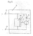
- FIG. 6 shows an embodiment in which the microcontroller 10 of the fire detector 9 are connected to a contact current sink 4 and the light emitting diode 5 and thus a fire detector with integrated line termination module is created.
- the device represents a particular embodiment of FIG. 5 in which the microcontroller 3, 10 in fire detector 9 and line termination module 1 need not be duplicated, since the microcontroller 10 of the fire detector takes over the control of the constant current sink 4.
- the contacts 11 of the fire detector 9 to be monitored fire detection line are not necessarily pluggable. These can also be designed as screw terminals etc.
- the solution according to the invention can be made mechanically compatible with the conventional connection resistance, so that a retrofitting of existing systems is possible.
- the system reliability increases due to interference when exceeding the permissible line impedance, so that in all resistance ranges faults are displayed.
- the quiescent current of the fire detection lines is voltage-independent by the constant current sink, which increases the reliability of the evaluation of the line current through the fire alarm panel.
- a visual display for trouble-free operation by the light indicator is provided.
Claims (8)
- Module actif de terminaison de ligne (1) destiné à la surveillance de l'impédance de lignes de détection incendie, le module de terminaison de ligne (1) comportant un injecteur de courant pilotable (4), un circuit électronique intelligent, de préférence un microcontrôleur, et un générateur de signal, l'injecteur de courant pilotable (4) étant relié électroniquement au circuit électronique intelligent, l'injecteur de courant pilotable (4) étant relié au moyen de contacts entre les câbles à surveiller de la ligne de détection incendie, le circuit électronique intelligent pilotant l'injecteur de courant (4) de telle manière qu'au repos, l'injecteur de courant (4) délivre le courant de repos au câble à surveiller, le circuit électronique intelligent coupant cycliquement pendant un court instant l'injecteur de courant (4) ou augmentant le courant constant et mesurant la tension du câble à surveiller avant et après la coupure ou l'augmentation de courant et, en cas de trop forte impédance, coupant l'injecteur de courant (4), le défaut de fonctionnement étant alors indiqué au moyen du générateur de signal une fois l'injecteur de courant (4) coupé.
- Module actif de terminaison de ligne (1) selon la revendication 1, caractérisé en ce que le module actif de terminaison de ligne (1) présente des contacts (2) enfichables dans l'embase d'une ligne de détection incendie.
- Module actif de terminaison de ligne (1) selon la revendication 1, caractérisé en ce que le module actif de terminaison de ligne (1) est intégré au montage d'un détecteur d'incendie (9).
- Module actif de terminaison de ligne (1) selon la revendication 3, caractérisé en ce que détecteur d'incendie (9) et module de terminaison de ligne (1) sont enfichables dans l'embase de la ligne de détection incendie.
- Module actif de terminaison de ligne (1) selon l'une des revendications 1 à 4, caractérisé en ce qu'un régulateur de tension (6) est monté en amont du circuit électronique intelligent.
- Module actif de terminaison de ligne (1) selon l'une des revendications 1 à 4, caractérisé en ce que le régulateur de tension (6) est intégré au circuit électronique intelligent.
- Module actif de terminaison de ligne (1) selon l'une des revendications 1 à 6, caractérisé en ce que le circuit électronique intelligent est constitué d'un circuit logique programmable.
- Module actif de terminaison de ligne (1) selon l'une des revendications 1 à 7, caractérisé en ce que le générateur de signal se présente sous la forme d'un d'afficheur lumineux, constitué de préférence d'une diode électroluminescente (5).
Priority Applications (7)
| Application Number | Priority Date | Filing Date | Title |
|---|---|---|---|
| PT80032709T PT2093737E (pt) | 2008-02-22 | 2008-02-22 | Módulo de fim de linha ativo |
| EP08003270.9A EP2093737B1 (fr) | 2008-02-22 | 2008-02-22 | Module de fin de ligne actif |
| ES08003270.9T ES2442520T3 (es) | 2008-02-22 | 2008-02-22 | Módulo de terminación de línea activo |
| PL08003270T PL2093737T3 (pl) | 2008-02-22 | 2008-02-22 | Aktywny moduł końcowy linii |
| US12/378,150 US20090212937A1 (en) | 2008-02-22 | 2009-02-11 | Active line termination module |
| CNA2009100064322A CN101515403A (zh) | 2008-02-22 | 2009-02-18 | 有源线路终端模块 |
| RU2009106144/08A RU2009106144A (ru) | 2008-02-22 | 2009-02-20 | Активный линейный концевой модуль |
Applications Claiming Priority (1)
| Application Number | Priority Date | Filing Date | Title |
|---|---|---|---|
| EP08003270.9A EP2093737B1 (fr) | 2008-02-22 | 2008-02-22 | Module de fin de ligne actif |
Publications (2)
| Publication Number | Publication Date |
|---|---|
| EP2093737A1 EP2093737A1 (fr) | 2009-08-26 |
| EP2093737B1 true EP2093737B1 (fr) | 2013-10-23 |
Family
ID=39619106
Family Applications (1)
| Application Number | Title | Priority Date | Filing Date |
|---|---|---|---|
| EP08003270.9A Active EP2093737B1 (fr) | 2008-02-22 | 2008-02-22 | Module de fin de ligne actif |
Country Status (7)
| Country | Link |
|---|---|
| US (1) | US20090212937A1 (fr) |
| EP (1) | EP2093737B1 (fr) |
| CN (1) | CN101515403A (fr) |
| ES (1) | ES2442520T3 (fr) |
| PL (1) | PL2093737T3 (fr) |
| PT (1) | PT2093737E (fr) |
| RU (1) | RU2009106144A (fr) |
Cited By (2)
| Publication number | Priority date | Publication date | Assignee | Title |
|---|---|---|---|---|
| CN111033588A (zh) * | 2017-08-10 | 2020-04-17 | 瓦格纳集团责任有限公司 | 操控和监控模块 |
| US11328580B2 (en) | 2018-05-29 | 2022-05-10 | Autronica Fire & Security As | Testing of a network of hazard warning devices |
Families Citing this family (15)
| Publication number | Priority date | Publication date | Assignee | Title |
|---|---|---|---|---|
| DE102008015999B4 (de) * | 2008-03-27 | 2011-04-21 | Novar Gmbh | Übertragungsweg - Prüfverfahren für eine Gefahrenmeldeanlage |
| US8427075B2 (en) * | 2008-12-12 | 2013-04-23 | Microchip Technology Incorporated | Constant current output sink or source |
| DE102010003353A1 (de) * | 2010-03-26 | 2011-09-29 | Robert Bosch Gmbh | Verfahren zum Überwachen von Leitungen |
| US9019674B2 (en) * | 2010-11-23 | 2015-04-28 | Fairchild Semiconductor Corporation | Input power port protection component |
| US8861164B2 (en) | 2011-02-04 | 2014-10-14 | Fairchild Semiconductor Corporation | Integrated overdrive and overvoltage protection device |
| NL2006386C2 (en) * | 2011-03-14 | 2012-09-17 | Astrea Intellectueel Eigendomsrecht B V | Device for testing the integrity of a signalling line. |
| GB201208289D0 (en) * | 2012-05-11 | 2012-06-20 | Computionics Ltd | An apparatus and associated method for measuring a series resistance |
| US9112346B2 (en) | 2013-03-14 | 2015-08-18 | Fairchild Semiconductor Corporation | Input power protection |
| US9172239B2 (en) | 2013-03-15 | 2015-10-27 | Fairchild Semiconductor Corporation | Methods and apparatus related to a precision input power protection device |
| EP2804163B1 (fr) * | 2013-05-17 | 2015-09-16 | Minimax GmbH & Co KG | Procédé et dispositif de détection des pannes dans des lignes de commande de systèmes de signalisation de danger et de systèmes de commande |
| US9374004B2 (en) * | 2013-06-28 | 2016-06-21 | Intel Corporation | I/O driver transmit swing control |
| US9735147B2 (en) | 2014-09-15 | 2017-08-15 | Fairchild Semiconductor Corporation | Fast and stable ultra low drop-out (LDO) voltage clamp device |
| US9940824B2 (en) * | 2015-03-13 | 2018-04-10 | Honeywell International Inc. | System and method of self-monitoring notification appliances |
| DE102018112299B4 (de) | 2018-05-23 | 2020-12-03 | Minimax Gmbh & Co. Kg | Einrichtung, Verfahren und Steuermodul zur Überwachung einer Zweidrahtleitung |
| EP3866133B1 (fr) * | 2020-02-17 | 2023-12-27 | Carrier Corporation | Module de sortie pour un système d'alarme incendie |
Citations (1)
| Publication number | Priority date | Publication date | Assignee | Title |
|---|---|---|---|---|
| WO2009087169A1 (fr) * | 2008-01-10 | 2009-07-16 | Robert Bosch Gmbh | Dispositif de contrôle pour un système d'alarme, système d'alarme et procédé de contrôle du système d'alarme |
Family Cites Families (5)
| Publication number | Priority date | Publication date | Assignee | Title |
|---|---|---|---|---|
| US5019805A (en) * | 1989-02-03 | 1991-05-28 | Flash-Alert Inc. | Smoke detector with strobed visual alarm and remote alarm coupling |
| DE10085118T1 (de) * | 1999-05-25 | 2003-06-05 | Ranco Inc Of Delaware Wilmingt | Verbesserte Sicht- und Hörsignalisierung für einen abgetasteten Alarmzustand |
| US20070035255A1 (en) * | 2005-08-09 | 2007-02-15 | James Shuster | LED strobe for hazard protection systems |
| PL1855261T5 (pl) * | 2006-05-11 | 2014-11-28 | Siemens Schweiz Ag | Sposób i urządzenie do monitorowania linii sygnalizacyjnej instalacji sygnalizatorów pożarowych pod kątem zakłóceń |
| FI120520B (fi) | 2008-01-04 | 2009-11-13 | Medixine Oy | Menetelmä ja järjestelmä päätelaitteella varustetun osapuolen varoittamiseksi |
-
2008
- 2008-02-22 ES ES08003270.9T patent/ES2442520T3/es active Active
- 2008-02-22 EP EP08003270.9A patent/EP2093737B1/fr active Active
- 2008-02-22 PT PT80032709T patent/PT2093737E/pt unknown
- 2008-02-22 PL PL08003270T patent/PL2093737T3/pl unknown
-
2009
- 2009-02-11 US US12/378,150 patent/US20090212937A1/en not_active Abandoned
- 2009-02-18 CN CNA2009100064322A patent/CN101515403A/zh active Pending
- 2009-02-20 RU RU2009106144/08A patent/RU2009106144A/ru not_active Application Discontinuation
Patent Citations (1)
| Publication number | Priority date | Publication date | Assignee | Title |
|---|---|---|---|---|
| WO2009087169A1 (fr) * | 2008-01-10 | 2009-07-16 | Robert Bosch Gmbh | Dispositif de contrôle pour un système d'alarme, système d'alarme et procédé de contrôle du système d'alarme |
Cited By (4)
| Publication number | Priority date | Publication date | Assignee | Title |
|---|---|---|---|---|
| CN111033588A (zh) * | 2017-08-10 | 2020-04-17 | 瓦格纳集团责任有限公司 | 操控和监控模块 |
| US10725096B2 (en) | 2017-08-10 | 2020-07-28 | Wagner Group Gmbh | Control and monitoring module |
| CN111033588B (zh) * | 2017-08-10 | 2021-12-28 | 瓦格纳集团责任有限公司 | 操控和监控模块 |
| US11328580B2 (en) | 2018-05-29 | 2022-05-10 | Autronica Fire & Security As | Testing of a network of hazard warning devices |
Also Published As
| Publication number | Publication date |
|---|---|
| RU2009106144A (ru) | 2010-08-27 |
| CN101515403A (zh) | 2009-08-26 |
| PT2093737E (pt) | 2013-12-05 |
| PL2093737T3 (pl) | 2014-03-31 |
| ES2442520T3 (es) | 2014-02-12 |
| EP2093737A1 (fr) | 2009-08-26 |
| US20090212937A1 (en) | 2009-08-27 |
Similar Documents
| Publication | Publication Date | Title |
|---|---|---|
| EP2093737B1 (fr) | Module de fin de ligne actif | |
| EP2804163B1 (fr) | Procédé et dispositif de détection des pannes dans des lignes de commande de systèmes de signalisation de danger et de systèmes de commande | |
| DE102008003799B4 (de) | Überwachungsvorrichtung für ein Meldesystem, Meldesystem und Verfahren zur Überwachung des Meldesystems | |
| DE2318803C3 (de) | Warnsignalanlage | |
| DE102013207775B4 (de) | Vorrichtung zum Erkennen einer Störung einer elektrischen Leitung | |
| EP3441958B1 (fr) | Module de commande et de surveillance | |
| EP2601719A2 (fr) | Procédé de commande de modules photovoltaïques individuels d'une installation photovoltaïque et dispositif de commande | |
| EP2277154B1 (fr) | Dispositif de surveillance destiné à surveiller le fonctionnement d'un système de signalisation, système de signalisation et procédé de surveillance | |
| EP3748599B1 (fr) | Procédé pour opérer et tester un système de signalisation de danger avec un système de bus, détecteurs pour connexion à un système de bus et système de signalisation de danger avec un système de bus. | |
| EP3030864B1 (fr) | Connecteur enfichable | |
| EP2916414B1 (fr) | Module de surveillance destiné à la surveillance de conducteur de mise à la terre | |
| DE202007007776U1 (de) | Anhängeranschlußgerät | |
| EP0756710B1 (fr) | Dispositif pour afficher la tension d'un conducteur d'un systeme d'alimentation en energie haute tension | |
| EP2169645A1 (fr) | Contrôle des lignes d'alerte d'une installation d'alerte au danger | |
| EP0632277B1 (fr) | Appareil pour test | |
| EP1816619B1 (fr) | Dispositif de surveillance redondant pour installations d'extinction d'incendie | |
| DE102008048929A1 (de) | Prüfung der Meldelinien einer Gefahrenmeldeanlage | |
| DE102008018642A1 (de) | Überwachungsschaltung und Verfahren zum Prüfen der Schaltung | |
| DE935648C (de) | Vorrichtung zur Kontrolle des Luftdruckes von Gummibereifungen | |
| EP2149956A1 (fr) | Système électrique modulaire et son procédé de fonctionnement | |
| DE4323731A1 (de) | Prüfgerät | |
| DE102016200914A1 (de) | Vorrichtung zur Leitungsüberwachung an einer Feststelleinrichtung von Brandschutztüren mit Rauchschaltern | |
| DE102010052080B4 (de) | Haussignalanlage und Verfahren zum Betreiben einer solchen | |
| EP0898349A1 (fr) | Dispositif de surveillance de courant et procédé de surveillance de courant | |
| DE102021115542A1 (de) | Schaltgerät für die Prozessmesstechnik |
Legal Events
| Date | Code | Title | Description |
|---|---|---|---|
| PUAI | Public reference made under article 153(3) epc to a published international application that has entered the european phase |
Free format text: ORIGINAL CODE: 0009012 |
|
| 17P | Request for examination filed |
Effective date: 20090130 |
|
| AK | Designated contracting states |
Kind code of ref document: A1 Designated state(s): AT BE BG CH CY CZ DE DK EE ES FI FR GB GR HR HU IE IS IT LI LT LU LV MC MT NL NO PL PT RO SE SI SK TR |
|
| AX | Request for extension of the european patent |
Extension state: AL BA MK RS |
|
| 17Q | First examination report despatched |
Effective date: 20100118 |
|
| AKX | Designation fees paid |
Designated state(s): AT BE BG CH CY CZ DE DK EE ES FI FR GB GR HR HU IE IS IT LI LT LU LV MC MT NL NO PL PT RO SE SI SK TR |
|
| GRAP | Despatch of communication of intention to grant a patent |
Free format text: ORIGINAL CODE: EPIDOSNIGR1 |
|
| INTG | Intention to grant announced |
Effective date: 20130716 |
|
| GRAS | Grant fee paid |
Free format text: ORIGINAL CODE: EPIDOSNIGR3 |
|
| GRAA | (expected) grant |
Free format text: ORIGINAL CODE: 0009210 |
|
| AK | Designated contracting states |
Kind code of ref document: B1 Designated state(s): AT BE BG CH CY CZ DE DK EE ES FI FR GB GR HR HU IE IS IT LI LT LU LV MC MT NL NO PL PT RO SE SI SK TR |
|
| REG | Reference to a national code |
Ref country code: GB Ref legal event code: FG4D Free format text: NOT ENGLISH |
|
| REG | Reference to a national code |
Ref country code: CH Ref legal event code: EP |
|
| REG | Reference to a national code |
Ref country code: AT Ref legal event code: REF Ref document number: 637948 Country of ref document: AT Kind code of ref document: T Effective date: 20131115 |
|
| REG | Reference to a national code |
Ref country code: IE Ref legal event code: FG4D Free format text: LANGUAGE OF EP DOCUMENT: GERMAN |
|
| REG | Reference to a national code |
Ref country code: PT Ref legal event code: SC4A Free format text: AVAILABILITY OF NATIONAL TRANSLATION Effective date: 20131128 |
|
| REG | Reference to a national code |
Ref country code: DE Ref legal event code: R096 Ref document number: 502008010838 Country of ref document: DE Effective date: 20131219 |
|
| REG | Reference to a national code |
Ref country code: SE Ref legal event code: TRGR |
|
| REG | Reference to a national code |
Ref country code: NL Ref legal event code: T3 Ref country code: ES Ref legal event code: FG2A Ref document number: 2442520 Country of ref document: ES Kind code of ref document: T3 Effective date: 20140212 |
|
| REG | Reference to a national code |
Ref country code: NO Ref legal event code: T2 Effective date: 20131023 |
|
| REG | Reference to a national code |
Ref country code: LT Ref legal event code: MG4D |
|
| PG25 | Lapsed in a contracting state [announced via postgrant information from national office to epo] |
Ref country code: LT Free format text: LAPSE BECAUSE OF FAILURE TO SUBMIT A TRANSLATION OF THE DESCRIPTION OR TO PAY THE FEE WITHIN THE PRESCRIBED TIME-LIMIT Effective date: 20131023 Ref country code: IS Free format text: LAPSE BECAUSE OF FAILURE TO SUBMIT A TRANSLATION OF THE DESCRIPTION OR TO PAY THE FEE WITHIN THE PRESCRIBED TIME-LIMIT Effective date: 20140223 Ref country code: HR Free format text: LAPSE BECAUSE OF FAILURE TO SUBMIT A TRANSLATION OF THE DESCRIPTION OR TO PAY THE FEE WITHIN THE PRESCRIBED TIME-LIMIT Effective date: 20131023 Ref country code: FI Free format text: LAPSE BECAUSE OF FAILURE TO SUBMIT A TRANSLATION OF THE DESCRIPTION OR TO PAY THE FEE WITHIN THE PRESCRIBED TIME-LIMIT Effective date: 20131023 |
|
| PG25 | Lapsed in a contracting state [announced via postgrant information from national office to epo] |
Ref country code: CY Free format text: LAPSE BECAUSE OF FAILURE TO SUBMIT A TRANSLATION OF THE DESCRIPTION OR TO PAY THE FEE WITHIN THE PRESCRIBED TIME-LIMIT Effective date: 20131023 |
|
| REG | Reference to a national code |
Ref country code: DE Ref legal event code: R097 Ref document number: 502008010838 Country of ref document: DE |
|
| PG25 | Lapsed in a contracting state [announced via postgrant information from national office to epo] |
Ref country code: EE Free format text: LAPSE BECAUSE OF FAILURE TO SUBMIT A TRANSLATION OF THE DESCRIPTION OR TO PAY THE FEE WITHIN THE PRESCRIBED TIME-LIMIT Effective date: 20131023 |
|
| PG25 | Lapsed in a contracting state [announced via postgrant information from national office to epo] |
Ref country code: CZ Free format text: LAPSE BECAUSE OF FAILURE TO SUBMIT A TRANSLATION OF THE DESCRIPTION OR TO PAY THE FEE WITHIN THE PRESCRIBED TIME-LIMIT Effective date: 20131023 Ref country code: RO Free format text: LAPSE BECAUSE OF FAILURE TO SUBMIT A TRANSLATION OF THE DESCRIPTION OR TO PAY THE FEE WITHIN THE PRESCRIBED TIME-LIMIT Effective date: 20131023 Ref country code: SK Free format text: LAPSE BECAUSE OF FAILURE TO SUBMIT A TRANSLATION OF THE DESCRIPTION OR TO PAY THE FEE WITHIN THE PRESCRIBED TIME-LIMIT Effective date: 20131023 |
|
| PLBE | No opposition filed within time limit |
Free format text: ORIGINAL CODE: 0009261 |
|
| STAA | Information on the status of an ep patent application or granted ep patent |
Free format text: STATUS: NO OPPOSITION FILED WITHIN TIME LIMIT |
|
| BERE | Be: lapsed |
Owner name: MINIMAX G.M.B.H. & CO. KG Effective date: 20140228 |
|
| PG25 | Lapsed in a contracting state [announced via postgrant information from national office to epo] |
Ref country code: MC Free format text: LAPSE BECAUSE OF FAILURE TO SUBMIT A TRANSLATION OF THE DESCRIPTION OR TO PAY THE FEE WITHIN THE PRESCRIBED TIME-LIMIT Effective date: 20131023 Ref country code: DK Free format text: LAPSE BECAUSE OF FAILURE TO SUBMIT A TRANSLATION OF THE DESCRIPTION OR TO PAY THE FEE WITHIN THE PRESCRIBED TIME-LIMIT Effective date: 20131023 Ref country code: LU Free format text: LAPSE BECAUSE OF FAILURE TO SUBMIT A TRANSLATION OF THE DESCRIPTION OR TO PAY THE FEE WITHIN THE PRESCRIBED TIME-LIMIT Effective date: 20140222 |
|
| 26N | No opposition filed |
Effective date: 20140724 |
|
| REG | Reference to a national code |
Ref country code: DE Ref legal event code: R097 Ref document number: 502008010838 Country of ref document: DE Effective date: 20140724 |
|
| REG | Reference to a national code |
Ref country code: IE Ref legal event code: MM4A |
|
| REG | Reference to a national code |
Ref country code: DE Ref legal event code: R082 Ref document number: 502008010838 Country of ref document: DE |
|
| PG25 | Lapsed in a contracting state [announced via postgrant information from national office to epo] |
Ref country code: IE Free format text: LAPSE BECAUSE OF NON-PAYMENT OF DUE FEES Effective date: 20140222 Ref country code: BE Free format text: LAPSE BECAUSE OF NON-PAYMENT OF DUE FEES Effective date: 20140228 |
|
| PG25 | Lapsed in a contracting state [announced via postgrant information from national office to epo] |
Ref country code: SI Free format text: LAPSE BECAUSE OF FAILURE TO SUBMIT A TRANSLATION OF THE DESCRIPTION OR TO PAY THE FEE WITHIN THE PRESCRIBED TIME-LIMIT Effective date: 20131023 |
|
| REG | Reference to a national code |
Ref country code: FR Ref legal event code: PLFP Year of fee payment: 9 |
|
| PG25 | Lapsed in a contracting state [announced via postgrant information from national office to epo] |
Ref country code: MT Free format text: LAPSE BECAUSE OF FAILURE TO SUBMIT A TRANSLATION OF THE DESCRIPTION OR TO PAY THE FEE WITHIN THE PRESCRIBED TIME-LIMIT Effective date: 20131023 |
|
| PG25 | Lapsed in a contracting state [announced via postgrant information from national office to epo] |
Ref country code: BG Free format text: LAPSE BECAUSE OF FAILURE TO SUBMIT A TRANSLATION OF THE DESCRIPTION OR TO PAY THE FEE WITHIN THE PRESCRIBED TIME-LIMIT Effective date: 20131023 |
|
| PG25 | Lapsed in a contracting state [announced via postgrant information from national office to epo] |
Ref country code: GR Free format text: LAPSE BECAUSE OF FAILURE TO SUBMIT A TRANSLATION OF THE DESCRIPTION OR TO PAY THE FEE WITHIN THE PRESCRIBED TIME-LIMIT Effective date: 20140124 |
|
| PG25 | Lapsed in a contracting state [announced via postgrant information from national office to epo] |
Ref country code: HU Free format text: LAPSE BECAUSE OF FAILURE TO SUBMIT A TRANSLATION OF THE DESCRIPTION OR TO PAY THE FEE WITHIN THE PRESCRIBED TIME-LIMIT; INVALID AB INITIO Effective date: 20080222 |
|
| REG | Reference to a national code |
Ref country code: FR Ref legal event code: PLFP Year of fee payment: 10 |
|
| REG | Reference to a national code |
Ref country code: FR Ref legal event code: PLFP Year of fee payment: 11 |
|
| PGFP | Annual fee paid to national office [announced via postgrant information from national office to epo] |
Ref country code: ES Payment date: 20210323 Year of fee payment: 14 |
|
| REG | Reference to a national code |
Ref country code: DE Ref legal event code: R081 Ref document number: 502008010838 Country of ref document: DE Owner name: MINIMAX GMBH, DE Free format text: FORMER OWNER: MINIMAX GMBH & CO. KG, 23843 BAD OLDESLOE, DE |
|
| PGFP | Annual fee paid to national office [announced via postgrant information from national office to epo] |
Ref country code: CH Payment date: 20220221 Year of fee payment: 15 Ref country code: AT Payment date: 20220215 Year of fee payment: 15 |
|
| PGFP | Annual fee paid to national office [announced via postgrant information from national office to epo] |
Ref country code: TR Payment date: 20220208 Year of fee payment: 15 Ref country code: SE Payment date: 20220221 Year of fee payment: 15 Ref country code: PT Payment date: 20220217 Year of fee payment: 15 Ref country code: PL Payment date: 20220214 Year of fee payment: 15 Ref country code: NO Payment date: 20220217 Year of fee payment: 15 Ref country code: NL Payment date: 20220216 Year of fee payment: 15 Ref country code: LV Payment date: 20220217 Year of fee payment: 15 Ref country code: IT Payment date: 20220228 Year of fee payment: 15 |
|
| REG | Reference to a national code |
Ref country code: ES Ref legal event code: FD2A Effective date: 20230331 |
|
| PG25 | Lapsed in a contracting state [announced via postgrant information from national office to epo] |
Ref country code: ES Free format text: LAPSE BECAUSE OF NON-PAYMENT OF DUE FEES Effective date: 20220223 |
|
| PGFP | Annual fee paid to national office [announced via postgrant information from national office to epo] |
Ref country code: FR Payment date: 20230217 Year of fee payment: 16 |
|
| PGFP | Annual fee paid to national office [announced via postgrant information from national office to epo] |
Ref country code: GB Payment date: 20230221 Year of fee payment: 16 Ref country code: DE Payment date: 20230216 Year of fee payment: 16 |
|
| REG | Reference to a national code |
Ref country code: NO Ref legal event code: MMEP |
|
| REG | Reference to a national code |
Ref country code: CH Ref legal event code: PL |
|
| REG | Reference to a national code |
Ref country code: SE Ref legal event code: EUG |
|
| REG | Reference to a national code |
Ref country code: NL Ref legal event code: MM Effective date: 20230301 |
|
| REG | Reference to a national code |
Ref country code: AT Ref legal event code: MM01 Ref document number: 637948 Country of ref document: AT Kind code of ref document: T Effective date: 20230222 |
|
| PG25 | Lapsed in a contracting state [announced via postgrant information from national office to epo] |
Ref country code: SE Free format text: LAPSE BECAUSE OF NON-PAYMENT OF DUE FEES Effective date: 20230223 Ref country code: PT Free format text: LAPSE BECAUSE OF NON-PAYMENT OF DUE FEES Effective date: 20230822 Ref country code: NO Free format text: LAPSE BECAUSE OF NON-PAYMENT OF DUE FEES Effective date: 20230228 Ref country code: LI Free format text: LAPSE BECAUSE OF NON-PAYMENT OF DUE FEES Effective date: 20230228 Ref country code: CH Free format text: LAPSE BECAUSE OF NON-PAYMENT OF DUE FEES Effective date: 20230228 Ref country code: AT Free format text: LAPSE BECAUSE OF NON-PAYMENT OF DUE FEES Effective date: 20230222 |
|
| PG25 | Lapsed in a contracting state [announced via postgrant information from national office to epo] |
Ref country code: NL Free format text: LAPSE BECAUSE OF NON-PAYMENT OF DUE FEES Effective date: 20230301 Ref country code: LV Free format text: LAPSE BECAUSE OF NON-PAYMENT OF DUE FEES Effective date: 20230222 |
|
| PG25 | Lapsed in a contracting state [announced via postgrant information from national office to epo] |
Ref country code: IT Free format text: LAPSE BECAUSE OF NON-PAYMENT OF DUE FEES Effective date: 20230222 |