EP2093550A2 - Lastsensor mit Lasterfassungselement und Trageelement und Verfahren zu dessen Herstellung - Google Patents
Lastsensor mit Lasterfassungselement und Trageelement und Verfahren zu dessen Herstellung Download PDFInfo
- Publication number
- EP2093550A2 EP2093550A2 EP09002205A EP09002205A EP2093550A2 EP 2093550 A2 EP2093550 A2 EP 2093550A2 EP 09002205 A EP09002205 A EP 09002205A EP 09002205 A EP09002205 A EP 09002205A EP 2093550 A2 EP2093550 A2 EP 2093550A2
- Authority
- EP
- European Patent Office
- Prior art keywords
- load
- spring
- base
- support portion
- detection element
- Prior art date
- Legal status (The legal status is an assumption and is not a legal conclusion. Google has not performed a legal analysis and makes no representation as to the accuracy of the status listed.)
- Granted
Links
- 238000001514 detection method Methods 0.000 title claims abstract description 126
- 238000000034 method Methods 0.000 title claims abstract description 48
- 238000004519 manufacturing process Methods 0.000 title claims abstract description 15
- 230000005489 elastic deformation Effects 0.000 claims abstract description 33
- 230000008878 coupling Effects 0.000 claims abstract description 7
- 238000010168 coupling process Methods 0.000 claims abstract description 7
- 238000005859 coupling reaction Methods 0.000 claims abstract description 7
- 238000003825 pressing Methods 0.000 claims abstract description 6
- 239000002245 particle Substances 0.000 claims description 20
- 238000009413 insulation Methods 0.000 claims description 18
- 239000011159 matrix material Substances 0.000 claims description 17
- WOCIAKWEIIZHES-UHFFFAOYSA-N ruthenium(iv) oxide Chemical compound O=[Ru]=O WOCIAKWEIIZHES-UHFFFAOYSA-N 0.000 claims description 14
- 239000011521 glass Substances 0.000 claims description 12
- 229910000975 Carbon steel Inorganic materials 0.000 claims description 6
- 239000010962 carbon steel Substances 0.000 claims description 6
- PNEYBMLMFCGWSK-UHFFFAOYSA-N aluminium oxide Inorganic materials [O-2].[O-2].[O-2].[Al+3].[Al+3] PNEYBMLMFCGWSK-UHFFFAOYSA-N 0.000 claims description 5
- 229910001220 stainless steel Inorganic materials 0.000 claims description 5
- 239000010935 stainless steel Substances 0.000 claims description 5
- 239000000463 material Substances 0.000 description 19
- MCMNRKCIXSYSNV-UHFFFAOYSA-N Zirconium dioxide Chemical compound O=[Zr]=O MCMNRKCIXSYSNV-UHFFFAOYSA-N 0.000 description 10
- 238000005482 strain hardening Methods 0.000 description 8
- 238000005187 foaming Methods 0.000 description 7
- 239000011230 binding agent Substances 0.000 description 5
- 239000002904 solvent Substances 0.000 description 5
- 238000003466 welding Methods 0.000 description 5
- 238000010586 diagram Methods 0.000 description 4
- 229910002075 lanthanum strontium manganite Inorganic materials 0.000 description 4
- 230000004048 modification Effects 0.000 description 4
- 238000012986 modification Methods 0.000 description 4
- 238000005245 sintering Methods 0.000 description 4
- 230000005540 biological transmission Effects 0.000 description 3
- 238000006073 displacement reaction Methods 0.000 description 3
- 230000008569 process Effects 0.000 description 3
- VYPSYNLAJGMNEJ-UHFFFAOYSA-N Silicium dioxide Chemical compound O=[Si]=O VYPSYNLAJGMNEJ-UHFFFAOYSA-N 0.000 description 2
- 230000008859 change Effects 0.000 description 2
- 239000002131 composite material Substances 0.000 description 2
- 230000006835 compression Effects 0.000 description 2
- 238000007906 compression Methods 0.000 description 2
- 238000007606 doctor blade method Methods 0.000 description 2
- 230000000694 effects Effects 0.000 description 2
- 238000001125 extrusion Methods 0.000 description 2
- 238000010438 heat treatment Methods 0.000 description 2
- 239000012774 insulation material Substances 0.000 description 2
- 239000002994 raw material Substances 0.000 description 2
- 230000035945 sensitivity Effects 0.000 description 2
- DHKHKXVYLBGOIT-UHFFFAOYSA-N 1,1-Diethoxyethane Chemical compound CCOC(C)OCC DHKHKXVYLBGOIT-UHFFFAOYSA-N 0.000 description 1
- OAYXUHPQHDHDDZ-UHFFFAOYSA-N 2-(2-butoxyethoxy)ethanol Chemical compound CCCCOCCOCCO OAYXUHPQHDHDDZ-UHFFFAOYSA-N 0.000 description 1
- -1 3Al2O3·2SiO2 Inorganic materials 0.000 description 1
- 239000004925 Acrylic resin Substances 0.000 description 1
- 229920000178 Acrylic resin Polymers 0.000 description 1
- 239000004156 Azodicarbonamide Substances 0.000 description 1
- 229910026161 MgAl2O4 Inorganic materials 0.000 description 1
- 229910000589 SAE 304 stainless steel Inorganic materials 0.000 description 1
- 229910052581 Si3N4 Inorganic materials 0.000 description 1
- 229910000831 Steel Inorganic materials 0.000 description 1
- WUOACPNHFRMFPN-UHFFFAOYSA-N alpha-terpineol Chemical compound CC1=CCC(C(C)(C)O)CC1 WUOACPNHFRMFPN-UHFFFAOYSA-N 0.000 description 1
- XOZUGNYVDXMRKW-AATRIKPKSA-N azodicarbonamide Chemical compound NC(=O)\N=N\C(N)=O XOZUGNYVDXMRKW-AATRIKPKSA-N 0.000 description 1
- 235000019399 azodicarbonamide Nutrition 0.000 description 1
- 239000000919 ceramic Substances 0.000 description 1
- CETPSERCERDGAM-UHFFFAOYSA-N ceric oxide Chemical compound O=[Ce]=O CETPSERCERDGAM-UHFFFAOYSA-N 0.000 description 1
- 229910000422 cerium(IV) oxide Inorganic materials 0.000 description 1
- 229910052681 coesite Inorganic materials 0.000 description 1
- 238000010276 construction Methods 0.000 description 1
- 229910052906 cristobalite Inorganic materials 0.000 description 1
- SQIFACVGCPWBQZ-UHFFFAOYSA-N delta-terpineol Natural products CC(C)(O)C1CCC(=C)CC1 SQIFACVGCPWBQZ-UHFFFAOYSA-N 0.000 description 1
- 239000010408 film Substances 0.000 description 1
- 239000007888 film coating Substances 0.000 description 1
- 238000009501 film coating Methods 0.000 description 1
- 239000006260 foam Substances 0.000 description 1
- MRELNEQAGSRDBK-UHFFFAOYSA-N lanthanum oxide Inorganic materials [O-2].[O-2].[O-2].[La+3].[La+3] MRELNEQAGSRDBK-UHFFFAOYSA-N 0.000 description 1
- 239000005355 lead glass Substances 0.000 description 1
- 238000005259 measurement Methods 0.000 description 1
- 239000000155 melt Substances 0.000 description 1
- 238000002844 melting Methods 0.000 description 1
- 230000008018 melting Effects 0.000 description 1
- 239000002184 metal Substances 0.000 description 1
- 230000007935 neutral effect Effects 0.000 description 1
- KTUFCUMIWABKDW-UHFFFAOYSA-N oxo(oxolanthaniooxy)lanthanum Chemical compound O=[La]O[La]=O KTUFCUMIWABKDW-UHFFFAOYSA-N 0.000 description 1
- 238000007639 printing Methods 0.000 description 1
- 230000002787 reinforcement Effects 0.000 description 1
- 239000011347 resin Substances 0.000 description 1
- 229920005989 resin Polymers 0.000 description 1
- 102220062469 rs786203185 Human genes 0.000 description 1
- 238000007650 screen-printing Methods 0.000 description 1
- 239000000377 silicon dioxide Substances 0.000 description 1
- 229910052596 spinel Inorganic materials 0.000 description 1
- 239000010959 steel Substances 0.000 description 1
- 229910052682 stishovite Inorganic materials 0.000 description 1
- 229940116411 terpineol Drugs 0.000 description 1
- 239000010409 thin film Substances 0.000 description 1
- 229910052905 tridymite Inorganic materials 0.000 description 1
- RUDFQVOCFDJEEF-UHFFFAOYSA-N yttrium(III) oxide Inorganic materials [O-2].[O-2].[O-2].[Y+3].[Y+3] RUDFQVOCFDJEEF-UHFFFAOYSA-N 0.000 description 1
Images


Classifications
-
- G—PHYSICS
- G01—MEASURING; TESTING
- G01L—MEASURING FORCE, STRESS, TORQUE, WORK, MECHANICAL POWER, MECHANICAL EFFICIENCY, OR FLUID PRESSURE
- G01L1/00—Measuring force or stress, in general
- G01L1/20—Measuring force or stress, in general by measuring variations in ohmic resistance of solid materials or of electrically-conductive fluids; by making use of electrokinetic cells, i.e. liquid-containing cells wherein an electrical potential is produced or varied upon the application of stress
-
- Y—GENERAL TAGGING OF NEW TECHNOLOGICAL DEVELOPMENTS; GENERAL TAGGING OF CROSS-SECTIONAL TECHNOLOGIES SPANNING OVER SEVERAL SECTIONS OF THE IPC; TECHNICAL SUBJECTS COVERED BY FORMER USPC CROSS-REFERENCE ART COLLECTIONS [XRACs] AND DIGESTS
- Y10—TECHNICAL SUBJECTS COVERED BY FORMER USPC
- Y10T—TECHNICAL SUBJECTS COVERED BY FORMER US CLASSIFICATION
- Y10T29/00—Metal working
- Y10T29/49—Method of mechanical manufacture
- Y10T29/49002—Electrical device making
- Y10T29/49117—Conductor or circuit manufacturing
-
- Y—GENERAL TAGGING OF NEW TECHNOLOGICAL DEVELOPMENTS; GENERAL TAGGING OF CROSS-SECTIONAL TECHNOLOGIES SPANNING OVER SEVERAL SECTIONS OF THE IPC; TECHNICAL SUBJECTS COVERED BY FORMER USPC CROSS-REFERENCE ART COLLECTIONS [XRACs] AND DIGESTS
- Y10—TECHNICAL SUBJECTS COVERED BY FORMER USPC
- Y10T—TECHNICAL SUBJECTS COVERED BY FORMER US CLASSIFICATION
- Y10T29/00—Metal working
- Y10T29/49—Method of mechanical manufacture
- Y10T29/49826—Assembling or joining
- Y10T29/49908—Joining by deforming
- Y10T29/49925—Inward deformation of aperture or hollow body wall
- Y10T29/49927—Hollow body is axially joined cup or tube
Definitions
- the present invention relates to a load sensor including a load detection element and a support element for detecting a load with high accuracy and a method for manufacturing a load sensor.
- a conventional load detection sensor includes a pressure sensitive member and an electrically insulation member.
- the sensor is disclosed in JP-A-2005-172793 , which corresponds to USP 7,059,203 .
- the pressure sensitive member has electric characteristics, which are changeable in accordance with stress applied to the sensor.
- the electrically insulation member is integrally formed on both sides of the pressure sensitive member.
- the pressure sensitive member is made of glass matrix including conductive particles dispersed in the matrix.
- the conductive particles are made of, for example, RuO 2 .
- the thickness of the pressure sensitive member is in a range between 1 ⁇ m and 200 ⁇ m.
- a pair of electrodes is disposed on the pressure sensitive member.
- a preliminary load may be applied to the load detection sensor so that not only a load along with a pressing direction but also a load along with a tensile direction is measured. This is disclosed in JP-A-2005-249598 corresponding to USP 6,997,060 and JP-A-H11-37860 .
- JP-A-2005-249598 and JP-A-H11-37860 teaches effects of the preliminary load application, a specific method for applying the load preliminary is not described in JP-A-2005-249598 and JP-A-H11-37860 .
- the magnitude of the preliminary load application has an appropriate range, and it is necessary to control the magnitude of the preliminary load application according to dimensions of an individual part.
- the load detection sensor does not have sufficient durability against a rotation torque, compared with compression.
- the method for controlling the magnitude of the preliminary load application is a screw method disclosed in JP-A-2005-249598 and JP-A-H11-37860 , both of the preliminary load and a rotation torque are applied to the load detection sensor.
- the load detection sensor has high rigidity in the compression direction.
- the screw method does not provide to apply the preliminary load sufficiently. When a screw is loosened, the preliminary load is much reduced. Further, the magnitude of the preliminary load is varied according to accuracy of a surface on which the screw contacts. However, it is difficult to form the surface having sufficient accuracy for securing the sufficient preliminary load. The preliminary load is applied to a small area of the surface, so that durability of the surface is reduced.
- a load sensor including a load detection element and a support element for detecting a load with high accuracy and sufficient durability. It is another object of the present disclosure to provide a method for manufacturing a load sensor.
- a method for manufacturing a load sensor including a load detection element and a support element, wherein the support element includes a base for mounting the load detection element on one side of the base and a spring for applying a preliminary load on the load detection element, wherein the spring includes a support portion for sandwiching the load detection element between the one side of the base and the support portion, a connection portion bonding to the base, and a connecting member for coupling the support portion and the connection portion, and wherein the support element transmits a detection load to the load detection element via the base and the spring
- the method includes: sandwiching the load detection element between the base and the spring; bonding the connection portion of the spring on the base so that the connecting member of the spring is deformed beyond the elastic deformation region to reach the plastic deformation region; pressing the support portion so that a contact surface of the support portion is plastically deformed, wherein the contact surface contacts the load detection element; and returning deformation of the connecting member to be in the elastic deformation region.
- the connecting member of the spring is deformed beyond the elastic deformation region to reach the plastic deformation region, and thereby, variation of parts in the load sensor is adjusted or controlled. Further, the contact surface of the support portion is plastically deformed, so that the deformation of the connecting member is returned to be in the elastic deformation region.
- durability of the spring is improved, and durability of the load sensor is improved.
- the preliminary load is controllable by adjusting the deformation of the connecting member of the spring and by controlling the plastic deformation of the support portion.
- the load is applied to the load detection element via the support portion of the spring.
- the support portion is made of certain material, and the support portion is deformed plastically, the work hardening proceeds so that the preliminary load is stably maintained.
- a load sensor includes: a load detection element; and a support element.
- the support element includes a base and a spring.
- the load detection element is mounted on one side of the base.
- the spring includes a support portion for sandwiching the load detection element between the one side of the base and the support portion, a connection portion connecting to the base, and a connecting member for coupling the support portion and the connection portion.
- the support portion includes a contact surface, which is plastically deformed. The contact surface contacts the load detection element.
- the spring is deformed so that the spring applies a preliminary load on the load detection element.
- the deformation of the spring provides to maintain the deformation of the connecting member within the elastic deformation region when a detection load has a predetermined variation range, and the support element transmits the detection load to the load detection element via the base and the spring.
- the deformation of the connecting member is in the elastic deformation range, so that the spring has excellent durability, and the preliminary load is applied to the load detection element stably.
- the preliminary load is controllable by adjusting the deformation of the connecting member of the spring and by controlling the plastic deformation of the support portion.
- the load is applied to the load detection element via the support portion of the spring.
- the support portion is made of certain material, and the support portion is deformed plastically, the work hardening proceeds so that the preliminary load is stably maintained.
- a method for manufacturing a load sensor including a load detection element and a support element includes: mounting the load detection element on one side of a base of the support element; sandwiching the load detection element between the one side of the base and a support portion of a spring of the support element; applying a first preliminary load on the load detection element via the support portion of the spring so that a dent is formed on a contact surface of the support portion, wherein the contact surface contacts the load detection element; applying a second preliminary load on a connection portion of the spring so that the connection portion contacts the base so that a connecting member of the spring is deformed beyond the elastic deformation region to reach the plastic deformation region, wherein the connecting member couples the support portion and the connection portion; bonding the base and the connection portion; applying a third preliminary load on the support portion via the support portion so that the contact surface of the support portion is plastically deformed and the dent on the contact surface becomes large; and returning deformation of the connecting member to be in the elastic deformation region.
- the connecting member of the spring is deformed beyond the elastic deformation region to reach the plastic deformation region, and thereby, variation of parts in the load sensor is adjusted or controlled. Further, the contact surface of the support portion is plastically deformed, so that the deformation of the connecting member is returned to be in the elastic deformation region.
- durability of the spring is improved, and durability of the load sensor is improved.
- the preliminary load is controllable by adjusting the deformation of the connecting member of the spring and by controlling the plastic deformation of the support portion.
- the load is applied to the load detection element via the support portion of the spring.
- the support portion is made of certain material, and the support portion is deformed plastically, the work hardening proceeds so that the preliminary load is stably maintained.
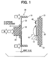
- a load sensor according to an example embodiment is shown in Fig. 1 .
- the sensor includes a load detection element 10, a support member such as a base 20 and a spring 30 and other parts such as a signal processor 40.
- the load detection element 10 includes a pair of frames 11, 12 made of insulation material, and a pressure sensitive element 13, which is sandwiched between the frames 11, 12 and is formed from a thin film.
- the insulation material of the frames 11, 12 is, for example, ceramics having high rigidity such as alumina, ZrO 2 , MgAl 2 O 4 , SiO 2 , 3Al 2 O 3 ⁇ 2SiO 2 , Y 2 O 3 , CeO 2 , La 2 O 3 , and Si 3 N 4 .
- the frames 11, 12 may be formed of an insulation film coating metal, which is insulated by the insulation film.
- the pressure sensitive element is made of material having electric properties changeable in accordance with a load applied to the element from an external device.
- the pressure sensitive element is made of glass matrix with conductive particles dispersed in the glass matrix.
- the glass matrix is made of borosilicate lead glass.
- the conductive particles are made of RuO 2 , lead ruthenate, or the like.
- the conductive particles are made of RuO 2 .
- the pressure sensitive element is formed by a doctor blade method, an extrusion molding method, a printing method such as a screen printing method and a transfer method. Specifically, the pressure sensitive element is formed such that RuO 2 particles together with foaming material and/or reinforcement material are dispersed in the glass matrix so that composite material is formed. Further, organic binder and/or solvent are added in the composite material, and they are processed to a paste. Then, the paste is shaped and sintered. Thus, the load detection element 10 is formed.
- the organic binder is made of cellurose resin or acrylic resin.
- the solvent is made of terpineol, butyl carbitol acetale, or the like.
- the organic binder and the solvent generate an air hole in the pressure sensitive element when the binder and the solvent are dried and delipidated in a heating step.
- the organic binder and the solvent function as an air hole forming member.
- the foaming material is made of organic foaming material such as azodicarbonamide or an inorganic foaming material.
- the air hole is easily and generally formed when the pressure sensitive element is formed in a sintering step, i.e., a heating step.
- the foaming material such as the organic or inorganic foaming material may be added in the raw material of the pressure sensitive element, and the foaming material foams in case of sintering so that the air hole is formed.
- the glass in the raw material of the pressure sensitive element melts so that the matrix made of glass is formed when the element is heated.
- the air hole in the melted glass becomes to have a spherical shape. It is preferred that the air hole has a spherical shape since stress concentration partially applied to the air hole is reduced. As a result, the load detection element 10 is prevented from being damaged and broken.
- the insulation member may be formed by a doctor blade method or an extrusion molding method.
- the insulation member may be formed by the same process as the pressure sensitive element, or formed by a different process from the pressure sensitive element.
- the pressure sensitive element and the insulation member are integrated.
- the pressure sensitive element and the insulation member may be integrated in the sintering process.
- the pressure sensitive element may be bonded to the insulation member with adhesion such as low melting point glass.
- the load detection element 10 may be formed of Zirconia and La 1-x Sr x MnO 3 (0 ⁇ X ⁇ 1) as main material.
- the material La 1-x Sr x MnO 3 (0 ⁇ X ⁇ 1) has pressure-resistant effect.
- the Zirconia particles function as a matrix material, and the La 1-x Sr x MnO 3 particles are dispersed such that the La 1-x Sr x MnO 3 particles are electrically coupled with each other.
- ohmic resistance of the element 10 is changed in accordance with the load applied to the element 10, and the load is detected based on the ohmic resistance of the element 10.
- the Zirconia particles have excellent heat resistance, so that temperature change in the element 10 is not generated. Thus, detection error is not caused by the temperature change in the element 10.
- the Zirconia particles have high toughness, so that the sensor has high durability against the load and pressure. When the strength of the load detection element 10 increases, the rigidity of the sensor is improved.
- the base 20 has a disk shape, and the load detection element 10 is fixed to a center portion of the base 20 on one side of the base 20.
- a flange 21 is disposed on an outer periphery of the base 20.
- the base 20 has rigidity higher than the detection element 10 and the spring 30.
- the base 20 is made of carbon steel.
- the spring 30 includes a connection portion 31 for connecting to the base 20, a support portion 32 for supporting the detection element 10 together with the base 20, a connecting member 33 for connecting between the support portion 32 and the connection portion 31, and a load transmission portion 34 for transmitting the load to the detection element 10.
- the support portion 32 is made of stainless steel such as SUS No. 304 steel and SUS No. 305 steel.
- SUS No. 304 and SUS No. 305 are defined in Japanese Industrial Standards.
- the connection portion 31, the connecting member 33 and the load transmission portion 34 are made of carbon steel.
- connection portion 31 has a cylindrical shape so that one end of the connection portion 31 in an axial direction is attachable to the flange 21 of the base 20.
- the one end of the connection portion 31 is fixed to the base 20.
- a connection between the one end of the connection portion 31 and the base 20 is performed by a welding method.
- the connecting member 33 is a diaphragm having a thin plate shape so that the connecting member 33 covers the other end of the connection portion 31.
- the support portion 32 has a disk shape and is disposed on a support portion side at a center of the connecting member 33.
- the load transmission portion 34 has a cylindrical shape and is disposed opposite to the support portion 32 at the center of the connecting member 33.
- the spring 30 can be deformed until the connecting member 33 is deformed to reach a plastic deformation region.
- the spring 30 provides to connect the connection portion 31 contacts the flange 21 and to contact the detection element 10 on the support portion 32.
- the deformation of the connecting member 33 can be controlled by adjusting the length of the connection portion 31 in the axial direction.
- the length of the connection portion 31 is set in view of variation of parts in the sensor such that the connecting member 33 is deformed to reach the plastic deformation region in any case.
- the sensor includes the signal processor 40, a wiring and a signal terminal (not shown).
- the processor 40 detects electric properties of the detection element 10 and outputs an electric signal in accordance with the magnitude of the load.
- the wiring communicates between the detection element 10 and the processor 40.
- the signal terminal communicates the signal with an external circuit.
- a method for manufacturing the load sensor includes a connecting step and a return step.
- the base 20 is bonded to the spring 30.
- the one end of the connection portion 31 of the spring 30 is bonded to the flange 21 of the base 20 by a welding method.
- the connecting step is performed in a manner that the load detection element 10 is sandwiched between a center of the base 20 on the one side and the support portion 32 of the spring 30.
- the support portion 32 of the spring 30 is adhered to the detection element 10, and then, the contact surface of the support portion 32 is dented to form a predetermined dent size.
- the contact surface of the support portion 32 is attached to the detection element 10.
- a predetermined load a is applied to the sensor so that the dent size in each sensor becomes the same.
- This step is shown as I in Figs. 1 and 3 .
- the dent is formed to have the dent size corresponding to the dent size I in Fig. 3 . Since the dent is formed, work hardening is caused in the support portion 32, so that stability in shape is improved.
- connection portion 31 is pressed so that the connecting member 33 is deformed.
- the other end of the connection portion 31 is adhered to the flange 21, and under this condition, the other end of the connection portion 31 is bonded to the flange 21 by a welding method.
- This step is shown as II in Figs. 1 and 2 .
- the second step II provides to absorb or adjust tolerance in each part of the sensor.
- a clearance F is formed between the other end of the connection portion 31 and the flange 21 before the one end of the connection portion 31 is pressed.
- This clearance F is variable in accordance with variation, i.e., tolerance in each part of the sensor.
- the connection portion 31 is displaced by the clearance F.
- the clearance F is set such that deformation of the connecting member 33 reaches a plastic deformation region even if the clearance F has a variation.
- A represents a case where the clearance F is large
- B represents a case where the clearance F is small.
- the original point of a graph B in a horizontal axis of Fig. 2 is slightly displaced from the original point of a graph A so that the graphs A and B are easily distinguished.
- a point of the graph B, at which the connection portion 31 is displaced and adhered to the flange 21, is the same as a point of the graph A.
- a return step the support portion 32 is pressed so that the contact surface of the support portion 32 contacting the load detection element 10 is plastically deformed, and the dent of the contact surface of the support portion 32 is increased.
- the plastic deformation of the support portion 32 is performed until the deformation of the connecting member 33 returns to the elastic deformation region.
- the stress in the connecting member 33 is adjusted so that the preliminary load is controlled.
- This step is shown as III in Figs. 1-3 .
- the support portion 32 is plastically deformed again, and thereby, the work hardening of the support portion 32 further proceeds, so that stability in shape is much improved.
- the magnitude of the preliminary load is not specified.
- the magnitude of the preliminary load is appropriately controlled in view of a load range to be detected by the sensor.
- the load to be detected by the sensor has a range H including a range in a pressing direction and a range in a tensile direction.
- the deformation of the connecting member 33 is set to be disposed in the elastic deformation range.
- the zero point of the range H is a neutral point of the range H.
- the deformation of the connecting member 33 is controlled by a method for controlling a load ⁇ to be applied, a method for controlling the magnitude of the deformation of the connecting member 33, a method for controlling a measurement value of the load detection element 10, or the like.
- the sensor includes the spring 30 and the base 20.
- the sensor may include another spring 50 and another base 22, which are shown in Figs. 5A and 5B .
- the spring 50 has a beam, both ends of which are supported.
- the spring has a both-end-clamped cantilever structure.
- a connection portion 51 of the spring 50 is bonded to a connection portion 23 of the base 22 by a welding method.
- the spring 50 has a connecting member 53 with a thickness, which is thicker than the spring 30.
- the thickness of the connecting member 53 is measured along with a direction sandwiching the load detection element 10.
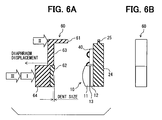
- the senor may include another spring 60 and another base 24, which are shown in Figs. 6A and 6B .
- the spring 60 has a cantilever structure, so that one end of the spring 60 is supported.
- a connection portion 61 of the spring 60 is bonded to a connection portion 25 of the base 24 by a welding method.
- a method for manufacturing a load sensor including a load detection element and a support element, wherein the support element includes a base for mounting the load detection element on one side of the base and a spring for applying a preliminary load on the load detection element, wherein the spring includes a support portion for sandwiching the load detection element between the one side of the base and the support portion, a connection portion bonding to the base, and a connecting member for coupling the support portion and the connection portion, and wherein the support element transmits a detection load to the load detection element via the base and the spring
- the method includes: sandwiching the load detection element between the base and the spring; bonding the connection portion of the spring on the base so that the connecting member of the spring is deformed beyond the elastic deformation region to reach the plastic deformation region; pressing the support portion so that a contact surface of the support portion is plastically deformed, wherein the contact surface contacts the load detection element; and returning deformation of the connecting member to be in the elastic deformation region.
- the connecting member of the spring is deformed beyond the elastic deformation region to reach the plastic deformation region, and thereby, variation of parts in the load sensor is adjusted or controlled. Further, the contact surface of the support portion is plastically deformed, so that the deformation of the connecting member is returned to be in the elastic deformation region.
- durability of the spring is improved, and durability of the load sensor is improved.
- the preliminary load is controllable by adjusting the deformation of the connecting member of the spring and by controlling the plastic deformation of the support portion.
- the load is applied to the load detection element via the support portion of the spring.
- the support portion is made of certain material, and the support portion is deformed plastically, the work hardening proceeds so that the preliminary load is stably maintained.
- the deformation of the connecting member is returned to maintain the deformation of the connecting member within the elastic deformation region when the detection load has a predetermined variation range and atmospheric temperature has a predetermined variation range.
- the load sensor when the load sensor is actually used, the deformation of the connecting member of the spring is always in the elastic deformation region. Accordingly, the preliminary load is stably and continuously applied to the load detection element.
- the load detection element has a contact portion, which contacts the contact surface of the support portion.
- the contact portion is made of alumina.
- the support portion is made of stainless steel.
- the connecting member is made of carbon steel.
- the variation of the preliminary load caused by thermal expansion is minimized.
- a center value of the variation of the preliminary load is set to be zero.
- the linear heat expansion coefficient of the alumina is 7.2 X 10 -6 /°C
- the linear heat expansion coefficient of the carbon steel such as S35C and SCM435 is 10.8-11.4 X 10 -6 /°C
- the linear heat expansion coefficient of the stainless steel such as SUS304 and SUS305 is 17.3 X 10 -6 /°C.
- Thickness of each part is set in such a manner that a sum of the linear heat expansion coefficient multiplied by a thickness in the connecting member and the linear heat expansion coefficient multiplied by a thickness in the load detection element is equal to the linear heat expansion coefficient multiplied by a thickness in the support portion. Thus, they are cancelled with each other, so that influence of heat is minimized. Specifically, the variation of the load caused by displacement of each part of the sensor is minimized.
- the spring has a rigidity along with a direction, to which the load detection element is pressed on the base, and the rigidity of the spring along with the direction is smaller than a rigidity of the spring along with another direction.
- the base has a disk shape.
- the support portion has a columnar shape.
- the connection portion has a cylindrical shape with one edge, which is bonded to a periphery of the base.
- the connecting member has a diaphragm shape, which couples with the other end of the cylindrical shape of the connection portion so that the diaphragm shape covers an opening of the cylindrical shape, and the diaphragm shape has a thin plate shape.
- the load detection element includes a pressure sensitive element and a pair of insulation elements.
- the pressure sensitive element is sandwiched between the pair of insulation elements so that both opposing sides of the pressure sensitive element are integrally covered with the pair of insulation elements.
- the pressure sensitive element has an electric property, which is changeable in accordance with a stress applied to the pressure sensitive element.
- the pressure sensitive element is formed from a matrix and a conductive particle.
- the matrix is made of glass, and the conductive particle is made of RuO 2 , and the conductive particle is dispersed in the matrix.
- the senor has high sensitivity and high accuracy to detect the load.
- a load sensor includes: a load detection element; and a support element.
- the support element includes a base and a spring.
- the load detection element is mounted on one side of the base.
- the spring includes a support portion for sandwiching the load detection element between the one side of the base and the support portion, a connection portion connecting to the base, and a connecting member for coupling the support portion and the connection portion.
- the support portion includes a contact surface, which is plastically deformed. The contact surface contacts the load detection element.
- the spring is deformed so that the spring applies a preliminary load on the load detection element.
- the deformation of the spring provides to maintain the deformation of the connecting member within the elastic deformation region when a detection load has a predetermined variation range, and the support element transmits the detection load to the load detection element via the base and the spring.
- the deformation of the connecting member is in the elastic deformation range, so that the spring has excellent durability, and the preliminary load is applied to the load detection element stably.
- the preliminary load is controllable by adjusting the deformation of the connecting member of the spring and by controlling the plastic deformation of the support portion.
- the load is applied to the load detection element via the support portion of the spring.
- the support portion is made of certain material, and the support portion is deformed plastically, the work hardening proceeds so that the preliminary load is stably maintained.
- a method for manufacturing a load sensor including a load detection element and a support element includes: mounting the load detection element on one side of a base of the support element; sandwiching the load detection element between the one side of the base and a support portion of a spring of the support element; applying a first preliminary load on the load detection element via the support portion of the spring so that a dent is formed on a contact surface of the support portion, wherein the contact surface contacts the load detection element; applying a second preliminary load on a connection portion of the spring so that the connection portion contacts the base so that a connecting member of the spring is deformed beyond the elastic deformation region to reach the plastic deformation region, wherein the connecting member couples the support portion and the connection portion; bonding the base and the connection portion; applying a third preliminary load on the support portion via the support portion so that the contact surface of the support portion is plastically deformed and the dent on the contact surface becomes large; and returning deformation of the connecting member to be in the elastic deformation region.
- the connecting member of the spring is deformed beyond the elastic deformation region to reach the plastic deformation region, and thereby, variation of parts in the load sensor is adjusted or controlled. Further, the contact surface of the support portion is plastically deformed, so that the deformation of the connecting member is returned to be in the elastic deformation region.
- durability of the spring is improved, and durability of the load sensor is improved.
- the preliminary load is controllable by adjusting the deformation of the connecting member of the spring and by controlling the plastic deformation of the support portion.
- the load is applied to the load detection element via the support portion of the spring.
- the support portion is made of certain material, and the support portion is deformed plastically, the work hardening proceeds so that the preliminary load is stably maintained.
Landscapes
- Physics & Mathematics (AREA)
- General Physics & Mathematics (AREA)
- Measurement Of Force In General (AREA)
Applications Claiming Priority (1)
| Application Number | Priority Date | Filing Date | Title |
|---|---|---|---|
| JP2008040475A JP4605232B2 (ja) | 2008-02-21 | 2008-02-21 | 荷重センサ及びその製造方法 |
Publications (3)
| Publication Number | Publication Date |
|---|---|
| EP2093550A2 true EP2093550A2 (de) | 2009-08-26 |
| EP2093550A3 EP2093550A3 (de) | 2010-07-14 |
| EP2093550B1 EP2093550B1 (de) | 2012-11-28 |
Family
ID=40638098
Family Applications (1)
| Application Number | Title | Priority Date | Filing Date |
|---|---|---|---|
| EP09002205A Expired - Fee Related EP2093550B1 (de) | 2008-02-21 | 2009-02-17 | Lastsensor mit Lasterfassungselement und Trageelement und Verfahren zu dessen Herstellung |
Country Status (3)
| Country | Link |
|---|---|
| US (1) | US8141431B2 (de) |
| EP (1) | EP2093550B1 (de) |
| JP (1) | JP4605232B2 (de) |
Cited By (2)
| Publication number | Priority date | Publication date | Assignee | Title |
|---|---|---|---|---|
| EP3388202A1 (de) * | 2015-11-20 | 2018-10-17 | Max Co., Ltd. | Werkzeug |
| US11154975B2 (en) | 2015-11-20 | 2021-10-26 | Max Co., Ltd. | Tool |
Families Citing this family (4)
| Publication number | Priority date | Publication date | Assignee | Title |
|---|---|---|---|---|
| US8327715B2 (en) * | 2009-07-02 | 2012-12-11 | Honeywell International Inc. | Force sensor apparatus |
| US20110203120A1 (en) * | 2010-02-23 | 2011-08-25 | Stephen Charles Witkus | Razor cartridge assembly |
| US8757001B2 (en) * | 2012-09-27 | 2014-06-24 | Honeywell International Inc. | Mechanically coupled force sensor on flexible platform assembly structure |
| JP6066767B2 (ja) * | 2013-02-28 | 2017-01-25 | シチズンファインデバイス株式会社 | 内燃機関用燃焼圧センサ及びその製造方法。 |
Citations (4)
| Publication number | Priority date | Publication date | Assignee | Title |
|---|---|---|---|---|
| JPH1137860A (ja) | 1997-07-15 | 1999-02-12 | Nippon Soken Inc | 荷重検出装置 |
| US20040000195A1 (en) | 2002-06-27 | 2004-01-01 | Kenichi Yanai | Pressure sensor |
| JP2005172793A (ja) | 2003-11-19 | 2005-06-30 | Toyota Central Res & Dev Lab Inc | 力学量センサ素子 |
| JP2005249598A (ja) | 2004-03-04 | 2005-09-15 | Denso Corp | 荷重検出装置 |
Family Cites Families (20)
| Publication number | Priority date | Publication date | Assignee | Title |
|---|---|---|---|---|
| JP3541570B2 (ja) * | 1996-06-12 | 2004-07-14 | 株式会社日立製作所 | エンジン用筒内圧センサ |
| US6279395B1 (en) * | 1999-02-05 | 2001-08-28 | Kistler Instrument Corporation | Annual shear element with radial preload |
| DE60115220T2 (de) * | 2000-03-23 | 2006-08-17 | Elliptec Resonant Actuator Ag | Vibrationsantrieb und herstellungsverfahren sowie verwendung desselben |
| JP4763175B2 (ja) | 2001-08-20 | 2011-08-31 | ヤマハ発動機株式会社 | 荷重検出装置 |
| JP2004278934A (ja) * | 2003-03-17 | 2004-10-07 | Ngk Spark Plug Co Ltd | 燃焼圧検知機能付きグロープラグ |
| JP4638659B2 (ja) * | 2003-05-21 | 2011-02-23 | 株式会社豊田中央研究所 | 圧力センサ |
| US6931934B2 (en) * | 2003-09-10 | 2005-08-23 | Honeywell International Inc. | Sensor top hat cover apparatus and method |
| US6969809B2 (en) * | 2003-09-22 | 2005-11-29 | Cts Corporation | Vehicle seat weight sensor |
| JP2005219689A (ja) * | 2004-02-09 | 2005-08-18 | Denso Corp | 乗員保護装置の制御システム |
| US20050249598A1 (en) * | 2004-05-05 | 2005-11-10 | Stanfield Young | Ceiling fan with multiple motors |
| JP4809594B2 (ja) * | 2004-08-02 | 2011-11-09 | 東京エレクトロン株式会社 | 検査装置 |
| US7302855B2 (en) * | 2004-10-28 | 2007-12-04 | Denso Corporation | Pressure detection device |
| DE102005010982A1 (de) * | 2005-03-03 | 2006-09-07 | Bizerba Gmbh & Co. Kg | Kraftmesszelle |
| JP4152403B2 (ja) * | 2005-06-30 | 2008-09-17 | 本田技研工業株式会社 | シートウエイトセンサ |
| JP2007107963A (ja) * | 2005-10-12 | 2007-04-26 | Toyota Central Res & Dev Lab Inc | 力学量センサ素子及びそれに用いる抵抗ペースト材料 |
| JP4940708B2 (ja) * | 2006-03-06 | 2012-05-30 | 株式会社豊田中央研究所 | 荷重センサ付きクランプボルト |
| JP2009020061A (ja) * | 2007-07-13 | 2009-01-29 | Denso Corp | 力学量センサ素子 |
| JP4687737B2 (ja) * | 2008-03-25 | 2011-05-25 | 株式会社デンソー | 荷重センサ |
| JP4687739B2 (ja) * | 2008-03-28 | 2011-05-25 | 株式会社デンソー | 荷重センサ |
| GB2462128B (en) * | 2008-07-25 | 2012-05-02 | Transense Technologies Plc | SAW sensor with adjustable preload |
-
2008
- 2008-02-21 JP JP2008040475A patent/JP4605232B2/ja not_active Expired - Fee Related
-
2009
- 2009-02-17 EP EP09002205A patent/EP2093550B1/de not_active Expired - Fee Related
- 2009-02-19 US US12/378,786 patent/US8141431B2/en not_active Expired - Fee Related
Patent Citations (6)
| Publication number | Priority date | Publication date | Assignee | Title |
|---|---|---|---|---|
| JPH1137860A (ja) | 1997-07-15 | 1999-02-12 | Nippon Soken Inc | 荷重検出装置 |
| US20040000195A1 (en) | 2002-06-27 | 2004-01-01 | Kenichi Yanai | Pressure sensor |
| JP2005172793A (ja) | 2003-11-19 | 2005-06-30 | Toyota Central Res & Dev Lab Inc | 力学量センサ素子 |
| US7059203B2 (en) | 2003-11-19 | 2006-06-13 | Kabushiki Kaisha Toyota Chuo Kenkyusho | Physical sensor |
| JP2005249598A (ja) | 2004-03-04 | 2005-09-15 | Denso Corp | 荷重検出装置 |
| US6997060B2 (en) | 2004-03-04 | 2006-02-14 | Denso Corporation | Load-detecting device |
Cited By (2)
| Publication number | Priority date | Publication date | Assignee | Title |
|---|---|---|---|---|
| EP3388202A1 (de) * | 2015-11-20 | 2018-10-17 | Max Co., Ltd. | Werkzeug |
| US11154975B2 (en) | 2015-11-20 | 2021-10-26 | Max Co., Ltd. | Tool |
Also Published As
| Publication number | Publication date |
|---|---|
| JP2009198324A (ja) | 2009-09-03 |
| EP2093550B1 (de) | 2012-11-28 |
| EP2093550A3 (de) | 2010-07-14 |
| JP4605232B2 (ja) | 2011-01-05 |
| US20090211365A1 (en) | 2009-08-27 |
| US8141431B2 (en) | 2012-03-27 |
Similar Documents
| Publication | Publication Date | Title |
|---|---|---|
| US7832284B2 (en) | Load sensor and manufacturing method for the same | |
| JP4577585B2 (ja) | 荷重センサの製造方法 | |
| EP2093550B1 (de) | Lastsensor mit Lasterfassungselement und Trageelement und Verfahren zu dessen Herstellung | |
| US8438931B2 (en) | Semiconductor strain sensor | |
| US7441467B2 (en) | Compression strain sensor | |
| US8569635B2 (en) | Tubular weight sensor with an inner projection | |
| CN101910812A (zh) | 载荷传感器 | |
| EP1043573B1 (de) | Scherkraftlastzelle | |
| US7043995B2 (en) | Pressure sensor with membrane and measuring elements arranged on the membrane | |
| JP2007506985A (ja) | ころがり軸受用のデータ検出兼処理システム及びこのようなシステムを持つころがり軸受 | |
| CN110325831A (zh) | 应变体及具备该应变体的力传感器 | |
| JP4566227B2 (ja) | 半導体歪センサーおよび半導体歪センサーの取付け方法 | |
| JP2001330522A (ja) | 荷重センサ | |
| EP3795969A1 (de) | Kraftmessgerät | |
| US20210190606A1 (en) | Strain gages and methods for manufacturing thereof | |
| EP0681261B1 (de) | Wandler für Hinweisanordnung mit Dickschichtwiderständen als Dehnungssensoren | |
| US7082844B1 (en) | Strain sensor having improved accuracy | |
| JP5034832B2 (ja) | 剪断力検出装置 | |
| US20230332964A1 (en) | Beam pressure sensor, pressure sensing device and electronic apparatus | |
| WO2021126261A1 (en) | Strain gages and methods for manufacturing thereof | |
| CN217585654U (zh) | 应变传感器 | |
| JPH06213734A (ja) | 荷重検出装置 | |
| JPH0552866A (ja) | 半導体加速度センサ支持装置 | |
| HK1036321A (en) | Tensile testing sensor for measuring mechanical jamming deformations on first installation and automatic calibrating based on said jamming |
Legal Events
| Date | Code | Title | Description |
|---|---|---|---|
| PUAI | Public reference made under article 153(3) epc to a published international application that has entered the european phase |
Free format text: ORIGINAL CODE: 0009012 |
|
| AK | Designated contracting states |
Kind code of ref document: A2 Designated state(s): AT BE BG CH CY CZ DE DK EE ES FI FR GB GR HR HU IE IS IT LI LT LU LV MC MK MT NL NO PL PT RO SE SI SK TR |
|
| AX | Request for extension of the european patent |
Extension state: AL BA RS |
|
| PUAL | Search report despatched |
Free format text: ORIGINAL CODE: 0009013 |
|
| AK | Designated contracting states |
Kind code of ref document: A3 Designated state(s): AT BE BG CH CY CZ DE DK EE ES FI FR GB GR HR HU IE IS IT LI LT LU LV MC MK MT NL NO PL PT RO SE SI SK TR |
|
| AX | Request for extension of the european patent |
Extension state: AL BA RS |
|
| 17P | Request for examination filed |
Effective date: 20101126 |
|
| AKX | Designation fees paid |
Designated state(s): DE FR |
|
| GRAP | Despatch of communication of intention to grant a patent |
Free format text: ORIGINAL CODE: EPIDOSNIGR1 |
|
| GRAS | Grant fee paid |
Free format text: ORIGINAL CODE: EPIDOSNIGR3 |
|
| GRAA | (expected) grant |
Free format text: ORIGINAL CODE: 0009210 |
|
| AK | Designated contracting states |
Kind code of ref document: B1 Designated state(s): DE FR |
|
| REG | Reference to a national code |
Ref country code: DE Ref legal event code: R096 Ref document number: 602009011468 Country of ref document: DE Effective date: 20130124 |
|
| REG | Reference to a national code |
Ref country code: DE Ref legal event code: R097 Ref document number: 602009011468 Country of ref document: DE |
|
| PLBE | No opposition filed within time limit |
Free format text: ORIGINAL CODE: 0009261 |
|
| STAA | Information on the status of an ep patent application or granted ep patent |
Free format text: STATUS: NO OPPOSITION FILED WITHIN TIME LIMIT |
|
| 26N | No opposition filed |
Effective date: 20130829 |
|
| REG | Reference to a national code |
Ref country code: DE Ref legal event code: R084 Ref document number: 602009011468 Country of ref document: DE Effective date: 20130910 |
|
| REG | Reference to a national code |
Ref country code: DE Ref legal event code: R097 Ref document number: 602009011468 Country of ref document: DE Effective date: 20130829 |
|
| REG | Reference to a national code |
Ref country code: FR Ref legal event code: PLFP Year of fee payment: 7 |
|
| PGFP | Annual fee paid to national office [announced via postgrant information from national office to epo] |
Ref country code: DE Payment date: 20150219 Year of fee payment: 7 |
|
| PGFP | Annual fee paid to national office [announced via postgrant information from national office to epo] |
Ref country code: FR Payment date: 20150219 Year of fee payment: 7 |
|
| REG | Reference to a national code |
Ref country code: DE Ref legal event code: R119 Ref document number: 602009011468 Country of ref document: DE |
|
| REG | Reference to a national code |
Ref country code: FR Ref legal event code: ST Effective date: 20161028 |
|
| PG25 | Lapsed in a contracting state [announced via postgrant information from national office to epo] |
Ref country code: FR Free format text: LAPSE BECAUSE OF NON-PAYMENT OF DUE FEES Effective date: 20160229 Ref country code: DE Free format text: LAPSE BECAUSE OF NON-PAYMENT OF DUE FEES Effective date: 20160901 |