EP2093518A1 - Collecteur solaire - Google Patents
Collecteur solaire Download PDFInfo
- Publication number
- EP2093518A1 EP2093518A1 EP09000490A EP09000490A EP2093518A1 EP 2093518 A1 EP2093518 A1 EP 2093518A1 EP 09000490 A EP09000490 A EP 09000490A EP 09000490 A EP09000490 A EP 09000490A EP 2093518 A1 EP2093518 A1 EP 2093518A1
- Authority
- EP
- European Patent Office
- Prior art keywords
- solar collector
- absorber tube
- collector according
- tube
- coating
- Prior art date
- Legal status (The legal status is an assumption and is not a legal conclusion. Google has not performed a legal analysis and makes no representation as to the accuracy of the status listed.)
- Withdrawn
Links
Images

Classifications
-
- F—MECHANICAL ENGINEERING; LIGHTING; HEATING; WEAPONS; BLASTING
- F24—HEATING; RANGES; VENTILATING
- F24S—SOLAR HEAT COLLECTORS; SOLAR HEAT SYSTEMS
- F24S10/00—Solar heat collectors using working fluids
- F24S10/40—Solar heat collectors using working fluids in absorbing elements surrounded by transparent enclosures, e.g. evacuated solar collectors
- F24S10/45—Solar heat collectors using working fluids in absorbing elements surrounded by transparent enclosures, e.g. evacuated solar collectors the enclosure being cylindrical
-
- F—MECHANICAL ENGINEERING; LIGHTING; HEATING; WEAPONS; BLASTING
- F24—HEATING; RANGES; VENTILATING
- F24S—SOLAR HEAT COLLECTORS; SOLAR HEAT SYSTEMS
- F24S23/00—Arrangements for concentrating solar-rays for solar heat collectors
- F24S23/70—Arrangements for concentrating solar-rays for solar heat collectors with reflectors
- F24S23/79—Arrangements for concentrating solar-rays for solar heat collectors with reflectors with spaced and opposed interacting reflective surfaces
-
- F—MECHANICAL ENGINEERING; LIGHTING; HEATING; WEAPONS; BLASTING
- F24—HEATING; RANGES; VENTILATING
- F24S—SOLAR HEAT COLLECTORS; SOLAR HEAT SYSTEMS
- F24S80/00—Details, accessories or component parts of solar heat collectors not provided for in groups F24S10/00-F24S70/00
- F24S80/50—Elements for transmitting incoming solar rays and preventing outgoing heat radiation; Transparent coverings
- F24S80/52—Elements for transmitting incoming solar rays and preventing outgoing heat radiation; Transparent coverings characterised by the material
-
- F—MECHANICAL ENGINEERING; LIGHTING; HEATING; WEAPONS; BLASTING
- F24—HEATING; RANGES; VENTILATING
- F24S—SOLAR HEAT COLLECTORS; SOLAR HEAT SYSTEMS
- F24S80/00—Details, accessories or component parts of solar heat collectors not provided for in groups F24S10/00-F24S70/00
- F24S80/50—Elements for transmitting incoming solar rays and preventing outgoing heat radiation; Transparent coverings
- F24S80/56—Elements for transmitting incoming solar rays and preventing outgoing heat radiation; Transparent coverings characterised by means for preventing heat loss
-
- F—MECHANICAL ENGINEERING; LIGHTING; HEATING; WEAPONS; BLASTING
- F24—HEATING; RANGES; VENTILATING
- F24S—SOLAR HEAT COLLECTORS; SOLAR HEAT SYSTEMS
- F24S23/00—Arrangements for concentrating solar-rays for solar heat collectors
- F24S23/70—Arrangements for concentrating solar-rays for solar heat collectors with reflectors
- F24S2023/86—Arrangements for concentrating solar-rays for solar heat collectors with reflectors in the form of reflective coatings
-
- Y—GENERAL TAGGING OF NEW TECHNOLOGICAL DEVELOPMENTS; GENERAL TAGGING OF CROSS-SECTIONAL TECHNOLOGIES SPANNING OVER SEVERAL SECTIONS OF THE IPC; TECHNICAL SUBJECTS COVERED BY FORMER USPC CROSS-REFERENCE ART COLLECTIONS [XRACs] AND DIGESTS
- Y02—TECHNOLOGIES OR APPLICATIONS FOR MITIGATION OR ADAPTATION AGAINST CLIMATE CHANGE
- Y02E—REDUCTION OF GREENHOUSE GAS [GHG] EMISSIONS, RELATED TO ENERGY GENERATION, TRANSMISSION OR DISTRIBUTION
- Y02E10/00—Energy generation through renewable energy sources
- Y02E10/40—Solar thermal energy, e.g. solar towers
- Y02E10/44—Heat exchange systems
Definitions
- the invention relates to a solar collector, with which the energy of the sunlight is convertible into heat energy.
- a solar collector consists in the simplest case of a tube, which is traversed by a heat transfer medium and exposed to solar radiation.
- Various devices are known from the prior art with which the efficiency of a solar collector can be improved.
- the heat transfer medium flowing through and acted upon by sunlight tube hereinafter referred to as absorber tube, often provided with a layer which improves the absorption of solar energy.
- the invention is therefore based on the technical problem of providing a solar collector, with which over the prior art, a higher efficiency in converting the energy of sunlight into heat energy can be achieved.
- a solar collector according to the invention comprises at least one absorber tube through which a heat transfer medium flows, behind which, viewed from the direction of the sun's rays, a mirror is arranged which reflects part of the sunlight passing the absorber tube in the direction of the absorber tube. Furthermore, a solar collector according to the invention comprises a substrate, which is arranged in front of the absorber tube and is transparent to sunlight, which has a coating which reflects heat radiation in the direction of the absorber tube, at least in one surface region. As a result, part of the heat energy radiated outward from the absorber tube is reflected back to the absorber tube, absorbed by the latter and discharged to the heat transfer medium, whereby the efficiency of a solar collector according to the invention is increased compared with the prior art.
- absorber tube all known from the prior art embodiments in terms of shape and absorption-increasing coating are suitable.
- the absorber tube is a straight tube.
- absorber tube in the sense of the invention also includes absorber tubes which, for example, are bent in a U-shape, have a plurality of turns or are even spirally formed.
- the transparent substrate which may be made of glass or plastic, for example, should reflect as much as possible of the heat radiated from the absorber tube back to the absorber tube, which is why a concave curvature of the transparent substrate towards the absorber tube is advantageous.
- a heat radiation-reflecting coating is not required behind the absorber tube because the mirror arranged there and reflecting the sunlight, whose mirror layer often consists of a silver-containing material, also reflects heat radiation.
- the thermal radiation-reflecting layer may be deposited on the side facing the absorber tube or on the side of the transparent substrate facing away from the absorber tube. Furthermore, it should be noted that the direct incidence of sunlight on the absorber tube is not affected too much by the transparent substrate with the heat radiation reflecting coating. In one embodiment, therefore, the thermal radiation reflective coating has a transmission with respect to the sunlight of at least 60%. A thermal radiation reflecting coating is therefore also advantageously formed with a thickness of 40 nm to 200 nm.
- the heat radiation-reflecting coating comprises at least one electrically conductive layer.
- Layers of one or more metals are suitable, for example, to reflect heat radiation.
- the heat radiation is reflected particularly well by layers that contain silver as a component or consist entirely of silver.
- Such a silver layer may have a layer thickness of 8 nm to 30 nm and preferably 10 nm to 20 nm.
- a thermal radiation reflective coating may also include at least one dielectric layer.
- a dielectric layer is formed such that it acts with respect to the sunlight anti-reflection.
- a dielectric layer consisting of an oxide or a nitride may also be formed as a protective layer.
- layers of titanium dioxide or of silicon nitride are suitable for acting with respect to sunlight and / or to act as a protective layer.
- an oxide layer is used as the anti-reflection layer and a silver-containing layer as the electrically conductive layer
- a dielectric layer is formed as a blocking layer between the silver-containing layer and the oxide layer.
- substoichiometric oxide layers such as substoichiometric nickel chromium oxide, are suitable as the blocking layer.
- CVD or PVD processes such as magnetron sputtering or vapor deposition can be used.
- the transparent substrate may be formed, for example, as a tube which encloses the absorber tube.
- the transparent substrate formed as a tube and / or the absorber tube may further have a round or oval cross-section and both tubes may also be concentric with each other or not concentric with each other.
- the tube and the absorber tube have a circular cross-section, it is advantageous if a vacuum is formed between the tube and the absorber tube.
- the electrically conductive layer was designed as a silver layer and deposited on the inside of the tube, this layer would oxidize in air and thereby lose their functionality. Vacuum conditions between the pipe and the absorber pipe can help here. In such a case, the heat losses of the absorber tube to the environment are reduced to the heat losses that result from heat radiation, because under vacuum conditions, no energy can be lost through convection.
- a gas such as a noble gas or even air
- a gas such as a noble gas or even air
- the introduction of a noble gas is recommended in particular in the case of design variants in which the tube and / or the absorber tube do not have a circular cross-section. This is because the pressure conditions under vacuum conditions between the tubes could lead to their deformation or destruction.
- the tube enclosing the absorber tube and carrying the thermal radiation reflective coating may also be formed as a double-walled tube with vacuum conditions between the double walls, the thermal radiation reflective coating being deposited in the vacuum region between the double walls.
- a simple installation of the absorber tube inside the tube can be carried out under atmospheric conditions.
- the mounted behind the absorber tube mirror for reflecting the sunlight can also be deposited as a mirror layer on the wall of the absorber tube enclosing the transparent substrate.
- the tubular transparent substrate may be a separate tube, which encloses the absorber tube and the transparent substrate, which carries the heat radiation-reflecting coating, or else the mirror layer and the heat radiation-reflecting layer may be deposited on the same substrate.
- the heat radiation reflective coating has an emissivity perpendicular to the coating surface of a maximum of 0.1.
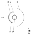
- Fig. 1 to 4 represents the illustrated arrow in each case the sun ray direction, and in the following description of the Fig. 1 to 4 the statements "in front of the absorber pipe” and “behind the absorber pipe” respectively relate to the direction of the sun's rays. All in the description of the Fig. 1 to 4 Named layers are deposited by magnetron sputtering.
- a first embodiment of a solar collector according to the invention is shown schematically in cross section.
- a concave mirror 13 is arranged, which reflects a part of the sunlight rays passing by the absorber tube 11 towards the absorber tube 11.
- a transparent glass substrate 14 which is concave towards the absorber tube.
- a heat radiation-reflecting coating 15 is deposited on the side of the glass substrate 14 facing the absorber tube 11.
- the thermal radiation reflective coating 15 comprises both a 15 nm thick silver layer, on which the heat radiated from the absorber tube 11 towards the glass substrate 14 is reflected, and a 60 nm thick titanium dioxide layer, which serves as a protective layer for the silver layer.
- a solar collector according to Fig. 1 falls a part of the sunlight through the transparent glass substrate 14 before it hits the absorber tube 11 where it is converted into heat energy.
- a part of the sunlight beams passing by the absorber tube 11 is also reflected by the mirror 13 towards the absorber tube 11 and thus contributes to an increased heat yield.
- the efficiency of the solar collector is further increased by a part of the radiated heat from the absorber tube 11 is reflected by the heat radiation reflective coating 15 on the glass substrate 14 back to the absorber tube 11.
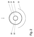
- FIG. 2 An alternative embodiment of a solar collector according to the invention is in Fig. 2 shown schematically in cross section.
- a concave mirror 23 is arranged, which reflects a part of the passing of the absorber tube 21 sunlight rays towards the absorber tube 21.
- the absorber tube 21 is completely enclosed by a transparent, tubular glass substrate 24.
- the glass substrate 24 Before the absorber tube 21, the glass substrate 24 has a heat radiation-reflecting coating 25 on a portion of its inner tube surface.
- the thermal radiation reflective coating 25 comprises, viewed from the glass substrate, first a 30 nm thick titanium dioxide layer, then a 12 nm thick silver layer and a 35 nm thick titanium dioxide layer.
- the titanium dioxide layers act here on the one hand anti-reflective with respect to the incident on the glass substrate 24 sunlight and on the other hand exert a protective function for the silver layer.
- Fig. 3 shows a further alternative embodiment of a solar collector according to the invention in a schematic cross-sectional view.
- An absorber tube 31 is enclosed in this embodiment by two transparent, tubular glass substrates 34 and 37, wherein glass substrate 34 is reflective as a carrier for thermal radiation Coating 35 and glass substrate 37 acts as a support for a sunlight reflecting mirror layer 33. All three tubes 31, 34 and 37 have a circular cross section and are aligned concentrically with each other.
- the heat radiation-reflecting coating 35 which is transparent to sunlight in sunlight, consists of a layer system which, starting from the glass substrate 34, comprises a 30 nm thick titanium dioxide layer, a 12 nm thick silver layer, a 20 nm thick titanium dioxide layer and a 20 nm thick silicon nitride layer.
- Layer as a cover and scratch protection layer comprises.
- the cavity 36 between the glass substrate 34 and absorber tube 31 is formed as a vacuum and thus, for example, from the description of Fig. 2 has known advantage in terms of almost nonexistent heat losses through heat conduction
- the cavity 38 between the glass substrates 34 and 37 is filled with the gas argon.
- the life of the mirror layer consisting of silver 33, which is applied to the inside of the glass tube 37 increased.
- the silver layer would be subject to oxidation in air conditions which would degrade its mirror properties with increasing time.
- a portion of the heat radiation emitted by the absorber tube 31 is reflected by the mirror layer 33 back to the absorber tube 31.
- Another part of the heat radiation emitted by the absorber tube is reflected by the heat radiation-reflecting coating 35 back to the absorber tube 31, whereby the efficiency of the solar collector after Fig. 3 is increased over the prior art.
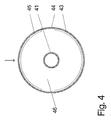
- FIG. 4 Another alternative embodiment of a solar collector according to the invention is in Fig. 4 shown schematically in cross section.
- An absorber tube 41 is completely enclosed by a transparent, tubular glass substrate 44.
- a mirror layer 43 is deposited in the region behind the absorber tube 41, which incident sunlight reflects toward the absorber tube 41.
- a heat radiation reflective coating 45 is deposited, which reflects a portion of the heat radiation emitted by the absorber tube 41 back to the absorber tube 41.
- a vacuum is formed in the cavity 46 between the glass substrate 44 and the absorber tube.
Applications Claiming Priority (1)
| Application Number | Priority Date | Filing Date | Title |
|---|---|---|---|
| DE102008010316A DE102008010316A1 (de) | 2008-02-21 | 2008-02-21 | Solarkollektor |
Publications (1)
| Publication Number | Publication Date |
|---|---|
| EP2093518A1 true EP2093518A1 (fr) | 2009-08-26 |
Family
ID=40666830
Family Applications (1)
| Application Number | Title | Priority Date | Filing Date |
|---|---|---|---|
| EP09000490A Withdrawn EP2093518A1 (fr) | 2008-02-21 | 2009-01-15 | Collecteur solaire |
Country Status (2)
| Country | Link |
|---|---|
| EP (1) | EP2093518A1 (fr) |
| DE (1) | DE102008010316A1 (fr) |
Cited By (11)
| Publication number | Priority date | Publication date | Assignee | Title |
|---|---|---|---|---|
| EP2366963A1 (fr) * | 2010-03-17 | 2011-09-21 | Solarafi S.à.r.l. | Capteur solaire à concentration |
| WO2012007166A1 (fr) * | 2010-07-14 | 2012-01-19 | Flagsol Gmbh | Dispositif d'héliothermie à haute température pour centrales |
| CN102589154A (zh) * | 2011-01-06 | 2012-07-18 | 胡达 | 集热器及集热系统 |
| CN102589169A (zh) * | 2011-01-17 | 2012-07-18 | 西门子聚集太阳能有限公司 | 受热器管及其制造方法、抛物形槽式收集器及其使用 |
| WO2012130283A3 (fr) * | 2011-03-29 | 2012-11-22 | Siemens Aktiengesellschaft | Tube récepteur de chaleur, procédé de fabrication de tube récepteur de chaleur, collecteur solaire à miroir cylindro-parabolique doté du tube récepteur, et utilisation du collecteur solaire à miroir cylindro-parabolique |
| US8378280B2 (en) | 2007-06-06 | 2013-02-19 | Areva Solar, Inc. | Integrated solar energy receiver-storage unit |
| US8739512B2 (en) | 2007-06-06 | 2014-06-03 | Areva Solar, Inc. | Combined cycle power plant |
| US8807128B2 (en) | 2007-08-27 | 2014-08-19 | Areva Solar, Inc. | Linear fresnel solar arrays |
| US9022020B2 (en) | 2007-08-27 | 2015-05-05 | Areva Solar, Inc. | Linear Fresnel solar arrays and drives therefor |
| CN105157257A (zh) * | 2015-09-28 | 2015-12-16 | 中国科学技术大学 | 一种槽式聚光型太阳能真空集热管 |
| EP3052868A1 (fr) * | 2013-09-30 | 2016-08-10 | IM, Do Sun | Collecteur d'énergie solaire et son système d'utilisation |
Families Citing this family (1)
| Publication number | Priority date | Publication date | Assignee | Title |
|---|---|---|---|---|
| CN108362010A (zh) * | 2018-05-15 | 2018-08-03 | 中国科学院电工研究所 | 一种用于高温的槽式太阳能集热管 |
Citations (6)
| Publication number | Priority date | Publication date | Assignee | Title |
|---|---|---|---|---|
| US4122831A (en) * | 1976-04-28 | 1978-10-31 | U.S. Philips Corporation | Solar collector comprising an elongate absorber in an evacuated transparent tube |
| EP0015017A1 (fr) * | 1979-02-09 | 1980-09-03 | Koninklijke Philips Electronics N.V. | Collecteur solaire avec tube transporteur de chaleur et système comportant au moins un tel collecteur |
| DE29808532U1 (de) | 1998-05-12 | 1998-10-01 | Schott Rohrglas Gmbh | Röhrenkollektor |
| EP1424315A1 (fr) * | 2002-11-29 | 2004-06-02 | Glas Trösch AG | Verre pare-soleil |
| DE102004020850A1 (de) | 2004-04-28 | 2005-11-24 | Schedletzky, Maik, Dr. | Röhrenkollektor zur Absorption von Lichtenergie |
| WO2006015815A1 (fr) * | 2004-08-05 | 2006-02-16 | Schott Ag | Absorbeur solaire |
Family Cites Families (1)
| Publication number | Priority date | Publication date | Assignee | Title |
|---|---|---|---|---|
| DE202007000823U1 (de) * | 2007-01-19 | 2007-03-29 | Veit Dennert Kg Baustoffbetriebe | Solarkollektor |
-
2008
- 2008-02-21 DE DE102008010316A patent/DE102008010316A1/de not_active Ceased
-
2009
- 2009-01-15 EP EP09000490A patent/EP2093518A1/fr not_active Withdrawn
Patent Citations (6)
| Publication number | Priority date | Publication date | Assignee | Title |
|---|---|---|---|---|
| US4122831A (en) * | 1976-04-28 | 1978-10-31 | U.S. Philips Corporation | Solar collector comprising an elongate absorber in an evacuated transparent tube |
| EP0015017A1 (fr) * | 1979-02-09 | 1980-09-03 | Koninklijke Philips Electronics N.V. | Collecteur solaire avec tube transporteur de chaleur et système comportant au moins un tel collecteur |
| DE29808532U1 (de) | 1998-05-12 | 1998-10-01 | Schott Rohrglas Gmbh | Röhrenkollektor |
| EP1424315A1 (fr) * | 2002-11-29 | 2004-06-02 | Glas Trösch AG | Verre pare-soleil |
| DE102004020850A1 (de) | 2004-04-28 | 2005-11-24 | Schedletzky, Maik, Dr. | Röhrenkollektor zur Absorption von Lichtenergie |
| WO2006015815A1 (fr) * | 2004-08-05 | 2006-02-16 | Schott Ag | Absorbeur solaire |
Cited By (13)
| Publication number | Priority date | Publication date | Assignee | Title |
|---|---|---|---|---|
| US8378280B2 (en) | 2007-06-06 | 2013-02-19 | Areva Solar, Inc. | Integrated solar energy receiver-storage unit |
| US8739512B2 (en) | 2007-06-06 | 2014-06-03 | Areva Solar, Inc. | Combined cycle power plant |
| US8807128B2 (en) | 2007-08-27 | 2014-08-19 | Areva Solar, Inc. | Linear fresnel solar arrays |
| US9022020B2 (en) | 2007-08-27 | 2015-05-05 | Areva Solar, Inc. | Linear Fresnel solar arrays and drives therefor |
| EP2366963A1 (fr) * | 2010-03-17 | 2011-09-21 | Solarafi S.à.r.l. | Capteur solaire à concentration |
| WO2012007166A1 (fr) * | 2010-07-14 | 2012-01-19 | Flagsol Gmbh | Dispositif d'héliothermie à haute température pour centrales |
| CN102589154A (zh) * | 2011-01-06 | 2012-07-18 | 胡达 | 集热器及集热系统 |
| CN102589169A (zh) * | 2011-01-17 | 2012-07-18 | 西门子聚集太阳能有限公司 | 受热器管及其制造方法、抛物形槽式收集器及其使用 |
| WO2012130283A3 (fr) * | 2011-03-29 | 2012-11-22 | Siemens Aktiengesellschaft | Tube récepteur de chaleur, procédé de fabrication de tube récepteur de chaleur, collecteur solaire à miroir cylindro-parabolique doté du tube récepteur, et utilisation du collecteur solaire à miroir cylindro-parabolique |
| US9732989B2 (en) | 2011-03-29 | 2017-08-15 | Siemens Concentrated Solar Power Ltd. | Heat receiver tube, method for manufacturing the heat receiver tube, parabolic trough collector with the receiver tube and use of the parabolic trough collector |
| EP3052868A1 (fr) * | 2013-09-30 | 2016-08-10 | IM, Do Sun | Collecteur d'énergie solaire et son système d'utilisation |
| EP3052868A4 (fr) * | 2013-09-30 | 2017-03-29 | IM, Do Sun | Collecteur d'énergie solaire et son système d'utilisation |
| CN105157257A (zh) * | 2015-09-28 | 2015-12-16 | 中国科学技术大学 | 一种槽式聚光型太阳能真空集热管 |
Also Published As
| Publication number | Publication date |
|---|---|
| DE102008010316A1 (de) | 2009-08-27 |
Similar Documents
| Publication | Publication Date | Title |
|---|---|---|
| EP2093518A1 (fr) | Collecteur solaire | |
| EP2253737B1 (fr) | Revêtement d'absorption à rayonnement sélectif et tuyau d'absorbeur avec un revêtement d'absorption à rayonnement sélectif | |
| DE102006056536B9 (de) | Strahlungsselektive Absorberbeschichtung, Absorberrohr und Verfahren zu dessen Herstellung | |
| EP2312234B1 (fr) | Revêtement d'absorption à rayonnement sélectif et tube d'absorbeur doté d'un revêtement d'absorption à rayonnement sélectif | |
| DE202009015334U1 (de) | Optisch wirksames Mehrschichtsystem für solare Absorption | |
| DE102009016708A1 (de) | Solarabsorber-Schichtsystem und Verfahren zu seiner Herstellung | |
| EP0529579A1 (fr) | Réflecteur solaire, son procédé de fabrication et son utilisation | |
| DE2612171A1 (de) | Sonnenkollektor mit evakuiertem absorber-abdeckrohr | |
| DE2838076A1 (de) | Sonnenkollektor | |
| EP0332177B1 (fr) | Revêtement protecteur à l'égard des rayons du soleil et/ou atténuateur du rayonnement thermique ayant un faible pouvoir réflecteur, une transparence élevée et une apparence neutre tant en transparence que du point de vue aspect extérieur | |
| DE69832396T2 (de) | Nichtabbildender sonnenkollektor | |
| DE4208710C2 (fr) | ||
| DE19840181B4 (de) | Parabolrinnenkollektor für ein Solarenergie-Kraftwerk | |
| DE60202142T2 (de) | Oberflächenbeschichtung für kollektorrohr eines linearen parabolischen sonnenkonzentrators | |
| DE102011083166A1 (de) | Verbundmaterial mit spektral selektivem Mehrschichtsystem und Verfahren zu dessen Herstellung | |
| EP2430375B1 (fr) | Tube de capteur sous vide et procédé de fabrication d'un tel tube de capteur sous vide | |
| DE102010034901A1 (de) | Solarthermische Anordnung | |
| DE10033240C2 (de) | Vakuumröhre für Solarenergieanlagen | |
| DE202008002287U1 (de) | Glasbauteil, umfassend wenigstens ein Glaselement aus einem herkömmlichen Glas und einer Funktionsbeschichtung | |
| DE202009011991U1 (de) | Solarthermischer Absorber | |
| DE2502594C2 (de) | Sonnenkollektor mit einem aus Metallblechen bestehenden Absorber mit Kanälen für eine die absorbierte Wärme abführende Flüssigkeit | |
| DE19680448B4 (de) | Reflektorvorrichtung für einen Sonnenkollektor | |
| AT402114B (de) | Sonnenkollektor | |
| DE2932683A1 (de) | Rohrfoermiger sonnenkollektor mit feststehendem wannenfoermigen konzentrator | |
| DE102009028393A1 (de) | Solarzelle |
Legal Events
| Date | Code | Title | Description |
|---|---|---|---|
| PUAI | Public reference made under article 153(3) epc to a published international application that has entered the european phase |
Free format text: ORIGINAL CODE: 0009012 |
|
| AK | Designated contracting states |
Kind code of ref document: A1 Designated state(s): AT BE BG CH CY CZ DE DK EE ES FI FR GB GR HR HU IE IS IT LI LT LU LV MC MK MT NL NO PL PT RO SE SI SK TR |
|
| AX | Request for extension of the european patent |
Extension state: AL BA RS |
|
| 17P | Request for examination filed |
Effective date: 20100226 |
|
| 17Q | First examination report despatched |
Effective date: 20100326 |
|
| AKX | Designation fees paid |
Designated state(s): AT BE BG CH CY CZ DE DK EE ES FI FR GB GR HR HU IE IS IT LI LT LU LV MC MK MT NL NO PL PT RO SE SI SK TR |
|
| D17P | Request for examination filed (deleted) | ||
| REG | Reference to a national code |
Ref country code: DE Ref legal event code: 8566 |
|
| STAA | Information on the status of an ep patent application or granted ep patent |
Free format text: STATUS: THE APPLICATION IS DEEMED TO BE WITHDRAWN |
|
| 18D | Application deemed to be withdrawn |
Effective date: 20100227 |