EP2093518A1 - Solar collector - Google Patents
Solar collector Download PDFInfo
- Publication number
- EP2093518A1 EP2093518A1 EP09000490A EP09000490A EP2093518A1 EP 2093518 A1 EP2093518 A1 EP 2093518A1 EP 09000490 A EP09000490 A EP 09000490A EP 09000490 A EP09000490 A EP 09000490A EP 2093518 A1 EP2093518 A1 EP 2093518A1
- Authority
- EP
- European Patent Office
- Prior art keywords
- solar collector
- absorber tube
- collector according
- tube
- coating
- Prior art date
- Legal status (The legal status is an assumption and is not a legal conclusion. Google has not performed a legal analysis and makes no representation as to the accuracy of the status listed.)
- Withdrawn
Links
Images

Classifications
-
- F—MECHANICAL ENGINEERING; LIGHTING; HEATING; WEAPONS; BLASTING
- F24—HEATING; RANGES; VENTILATING
- F24S—SOLAR HEAT COLLECTORS; SOLAR HEAT SYSTEMS
- F24S10/00—Solar heat collectors using working fluids
- F24S10/40—Solar heat collectors using working fluids in absorbing elements surrounded by transparent enclosures, e.g. evacuated solar collectors
- F24S10/45—Solar heat collectors using working fluids in absorbing elements surrounded by transparent enclosures, e.g. evacuated solar collectors the enclosure being cylindrical
-
- F—MECHANICAL ENGINEERING; LIGHTING; HEATING; WEAPONS; BLASTING
- F24—HEATING; RANGES; VENTILATING
- F24S—SOLAR HEAT COLLECTORS; SOLAR HEAT SYSTEMS
- F24S23/00—Arrangements for concentrating solar-rays for solar heat collectors
- F24S23/70—Arrangements for concentrating solar-rays for solar heat collectors with reflectors
- F24S23/79—Arrangements for concentrating solar-rays for solar heat collectors with reflectors with spaced and opposed interacting reflective surfaces
-
- F—MECHANICAL ENGINEERING; LIGHTING; HEATING; WEAPONS; BLASTING
- F24—HEATING; RANGES; VENTILATING
- F24S—SOLAR HEAT COLLECTORS; SOLAR HEAT SYSTEMS
- F24S80/00—Details, accessories or component parts of solar heat collectors not provided for in groups F24S10/00-F24S70/00
- F24S80/50—Elements for transmitting incoming solar rays and preventing outgoing heat radiation; Transparent coverings
- F24S80/52—Elements for transmitting incoming solar rays and preventing outgoing heat radiation; Transparent coverings characterised by the material
-
- F—MECHANICAL ENGINEERING; LIGHTING; HEATING; WEAPONS; BLASTING
- F24—HEATING; RANGES; VENTILATING
- F24S—SOLAR HEAT COLLECTORS; SOLAR HEAT SYSTEMS
- F24S80/00—Details, accessories or component parts of solar heat collectors not provided for in groups F24S10/00-F24S70/00
- F24S80/50—Elements for transmitting incoming solar rays and preventing outgoing heat radiation; Transparent coverings
- F24S80/56—Elements for transmitting incoming solar rays and preventing outgoing heat radiation; Transparent coverings characterised by means for preventing heat loss
-
- F—MECHANICAL ENGINEERING; LIGHTING; HEATING; WEAPONS; BLASTING
- F24—HEATING; RANGES; VENTILATING
- F24S—SOLAR HEAT COLLECTORS; SOLAR HEAT SYSTEMS
- F24S23/00—Arrangements for concentrating solar-rays for solar heat collectors
- F24S23/70—Arrangements for concentrating solar-rays for solar heat collectors with reflectors
- F24S2023/86—Arrangements for concentrating solar-rays for solar heat collectors with reflectors in the form of reflective coatings
-
- Y—GENERAL TAGGING OF NEW TECHNOLOGICAL DEVELOPMENTS; GENERAL TAGGING OF CROSS-SECTIONAL TECHNOLOGIES SPANNING OVER SEVERAL SECTIONS OF THE IPC; TECHNICAL SUBJECTS COVERED BY FORMER USPC CROSS-REFERENCE ART COLLECTIONS [XRACs] AND DIGESTS
- Y02—TECHNOLOGIES OR APPLICATIONS FOR MITIGATION OR ADAPTATION AGAINST CLIMATE CHANGE
- Y02E—REDUCTION OF GREENHOUSE GAS [GHG] EMISSIONS, RELATED TO ENERGY GENERATION, TRANSMISSION OR DISTRIBUTION
- Y02E10/00—Energy generation through renewable energy sources
- Y02E10/40—Solar thermal energy, e.g. solar towers
- Y02E10/44—Heat exchange systems
Definitions
- the invention relates to a solar collector, with which the energy of the sunlight is convertible into heat energy.
- a solar collector consists in the simplest case of a tube, which is traversed by a heat transfer medium and exposed to solar radiation.
- Various devices are known from the prior art with which the efficiency of a solar collector can be improved.
- the heat transfer medium flowing through and acted upon by sunlight tube hereinafter referred to as absorber tube, often provided with a layer which improves the absorption of solar energy.
- the invention is therefore based on the technical problem of providing a solar collector, with which over the prior art, a higher efficiency in converting the energy of sunlight into heat energy can be achieved.
- a solar collector according to the invention comprises at least one absorber tube through which a heat transfer medium flows, behind which, viewed from the direction of the sun's rays, a mirror is arranged which reflects part of the sunlight passing the absorber tube in the direction of the absorber tube. Furthermore, a solar collector according to the invention comprises a substrate, which is arranged in front of the absorber tube and is transparent to sunlight, which has a coating which reflects heat radiation in the direction of the absorber tube, at least in one surface region. As a result, part of the heat energy radiated outward from the absorber tube is reflected back to the absorber tube, absorbed by the latter and discharged to the heat transfer medium, whereby the efficiency of a solar collector according to the invention is increased compared with the prior art.
- absorber tube all known from the prior art embodiments in terms of shape and absorption-increasing coating are suitable.
- the absorber tube is a straight tube.
- absorber tube in the sense of the invention also includes absorber tubes which, for example, are bent in a U-shape, have a plurality of turns or are even spirally formed.
- the transparent substrate which may be made of glass or plastic, for example, should reflect as much as possible of the heat radiated from the absorber tube back to the absorber tube, which is why a concave curvature of the transparent substrate towards the absorber tube is advantageous.
- a heat radiation-reflecting coating is not required behind the absorber tube because the mirror arranged there and reflecting the sunlight, whose mirror layer often consists of a silver-containing material, also reflects heat radiation.
- the thermal radiation-reflecting layer may be deposited on the side facing the absorber tube or on the side of the transparent substrate facing away from the absorber tube. Furthermore, it should be noted that the direct incidence of sunlight on the absorber tube is not affected too much by the transparent substrate with the heat radiation reflecting coating. In one embodiment, therefore, the thermal radiation reflective coating has a transmission with respect to the sunlight of at least 60%. A thermal radiation reflecting coating is therefore also advantageously formed with a thickness of 40 nm to 200 nm.
- the heat radiation-reflecting coating comprises at least one electrically conductive layer.
- Layers of one or more metals are suitable, for example, to reflect heat radiation.
- the heat radiation is reflected particularly well by layers that contain silver as a component or consist entirely of silver.
- Such a silver layer may have a layer thickness of 8 nm to 30 nm and preferably 10 nm to 20 nm.
- a thermal radiation reflective coating may also include at least one dielectric layer.
- a dielectric layer is formed such that it acts with respect to the sunlight anti-reflection.
- a dielectric layer consisting of an oxide or a nitride may also be formed as a protective layer.
- layers of titanium dioxide or of silicon nitride are suitable for acting with respect to sunlight and / or to act as a protective layer.
- an oxide layer is used as the anti-reflection layer and a silver-containing layer as the electrically conductive layer
- a dielectric layer is formed as a blocking layer between the silver-containing layer and the oxide layer.
- substoichiometric oxide layers such as substoichiometric nickel chromium oxide, are suitable as the blocking layer.
- CVD or PVD processes such as magnetron sputtering or vapor deposition can be used.
- the transparent substrate may be formed, for example, as a tube which encloses the absorber tube.
- the transparent substrate formed as a tube and / or the absorber tube may further have a round or oval cross-section and both tubes may also be concentric with each other or not concentric with each other.
- the tube and the absorber tube have a circular cross-section, it is advantageous if a vacuum is formed between the tube and the absorber tube.
- the electrically conductive layer was designed as a silver layer and deposited on the inside of the tube, this layer would oxidize in air and thereby lose their functionality. Vacuum conditions between the pipe and the absorber pipe can help here. In such a case, the heat losses of the absorber tube to the environment are reduced to the heat losses that result from heat radiation, because under vacuum conditions, no energy can be lost through convection.
- a gas such as a noble gas or even air
- a gas such as a noble gas or even air
- the introduction of a noble gas is recommended in particular in the case of design variants in which the tube and / or the absorber tube do not have a circular cross-section. This is because the pressure conditions under vacuum conditions between the tubes could lead to their deformation or destruction.
- the tube enclosing the absorber tube and carrying the thermal radiation reflective coating may also be formed as a double-walled tube with vacuum conditions between the double walls, the thermal radiation reflective coating being deposited in the vacuum region between the double walls.
- a simple installation of the absorber tube inside the tube can be carried out under atmospheric conditions.
- the mounted behind the absorber tube mirror for reflecting the sunlight can also be deposited as a mirror layer on the wall of the absorber tube enclosing the transparent substrate.
- the tubular transparent substrate may be a separate tube, which encloses the absorber tube and the transparent substrate, which carries the heat radiation-reflecting coating, or else the mirror layer and the heat radiation-reflecting layer may be deposited on the same substrate.
- the heat radiation reflective coating has an emissivity perpendicular to the coating surface of a maximum of 0.1.
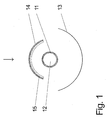
- Fig. 1 to 4 represents the illustrated arrow in each case the sun ray direction, and in the following description of the Fig. 1 to 4 the statements "in front of the absorber pipe” and “behind the absorber pipe” respectively relate to the direction of the sun's rays. All in the description of the Fig. 1 to 4 Named layers are deposited by magnetron sputtering.
- a first embodiment of a solar collector according to the invention is shown schematically in cross section.
- a concave mirror 13 is arranged, which reflects a part of the sunlight rays passing by the absorber tube 11 towards the absorber tube 11.
- a transparent glass substrate 14 which is concave towards the absorber tube.
- a heat radiation-reflecting coating 15 is deposited on the side of the glass substrate 14 facing the absorber tube 11.
- the thermal radiation reflective coating 15 comprises both a 15 nm thick silver layer, on which the heat radiated from the absorber tube 11 towards the glass substrate 14 is reflected, and a 60 nm thick titanium dioxide layer, which serves as a protective layer for the silver layer.
- a solar collector according to Fig. 1 falls a part of the sunlight through the transparent glass substrate 14 before it hits the absorber tube 11 where it is converted into heat energy.
- a part of the sunlight beams passing by the absorber tube 11 is also reflected by the mirror 13 towards the absorber tube 11 and thus contributes to an increased heat yield.
- the efficiency of the solar collector is further increased by a part of the radiated heat from the absorber tube 11 is reflected by the heat radiation reflective coating 15 on the glass substrate 14 back to the absorber tube 11.
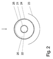
- FIG. 2 An alternative embodiment of a solar collector according to the invention is in Fig. 2 shown schematically in cross section.
- a concave mirror 23 is arranged, which reflects a part of the passing of the absorber tube 21 sunlight rays towards the absorber tube 21.
- the absorber tube 21 is completely enclosed by a transparent, tubular glass substrate 24.
- the glass substrate 24 Before the absorber tube 21, the glass substrate 24 has a heat radiation-reflecting coating 25 on a portion of its inner tube surface.
- the thermal radiation reflective coating 25 comprises, viewed from the glass substrate, first a 30 nm thick titanium dioxide layer, then a 12 nm thick silver layer and a 35 nm thick titanium dioxide layer.
- the titanium dioxide layers act here on the one hand anti-reflective with respect to the incident on the glass substrate 24 sunlight and on the other hand exert a protective function for the silver layer.
- Fig. 3 shows a further alternative embodiment of a solar collector according to the invention in a schematic cross-sectional view.
- An absorber tube 31 is enclosed in this embodiment by two transparent, tubular glass substrates 34 and 37, wherein glass substrate 34 is reflective as a carrier for thermal radiation Coating 35 and glass substrate 37 acts as a support for a sunlight reflecting mirror layer 33. All three tubes 31, 34 and 37 have a circular cross section and are aligned concentrically with each other.
- the heat radiation-reflecting coating 35 which is transparent to sunlight in sunlight, consists of a layer system which, starting from the glass substrate 34, comprises a 30 nm thick titanium dioxide layer, a 12 nm thick silver layer, a 20 nm thick titanium dioxide layer and a 20 nm thick silicon nitride layer.
- Layer as a cover and scratch protection layer comprises.
- the cavity 36 between the glass substrate 34 and absorber tube 31 is formed as a vacuum and thus, for example, from the description of Fig. 2 has known advantage in terms of almost nonexistent heat losses through heat conduction
- the cavity 38 between the glass substrates 34 and 37 is filled with the gas argon.
- the life of the mirror layer consisting of silver 33, which is applied to the inside of the glass tube 37 increased.
- the silver layer would be subject to oxidation in air conditions which would degrade its mirror properties with increasing time.
- a portion of the heat radiation emitted by the absorber tube 31 is reflected by the mirror layer 33 back to the absorber tube 31.
- Another part of the heat radiation emitted by the absorber tube is reflected by the heat radiation-reflecting coating 35 back to the absorber tube 31, whereby the efficiency of the solar collector after Fig. 3 is increased over the prior art.
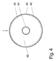
- FIG. 4 Another alternative embodiment of a solar collector according to the invention is in Fig. 4 shown schematically in cross section.
- An absorber tube 41 is completely enclosed by a transparent, tubular glass substrate 44.
- a mirror layer 43 is deposited in the region behind the absorber tube 41, which incident sunlight reflects toward the absorber tube 41.
- a heat radiation reflective coating 45 is deposited, which reflects a portion of the heat radiation emitted by the absorber tube 41 back to the absorber tube 41.
- a vacuum is formed in the cavity 46 between the glass substrate 44 and the absorber tube.
Abstract
Description
Die Erfindung betrifft einen Solarkollektor, mit dem die Energie des Sonnenlichts in Wärmeenergie umwandelbar ist.The invention relates to a solar collector, with which the energy of the sunlight is convertible into heat energy.
Ein Solarkollektor besteht im einfachsten Fall aus einem Rohr, das von einem Wärmeträgermedium durchflossen und mit Sonnenstrahlung beaufschlagt wird. Aus dem Stand der Technik sind verschiedene Vorrichtungen bekannt, mit denen der Wirkungsgrad eines Solarkollektors verbessert werden kann. So ist das vom Wärmeträgermedium durchflossene und mit Sonnenlicht beaufschlagte Rohr, nachfolgend als Absorberrohr bezeichnet, oftmals mit einer Schicht versehen, welche das Absorbieren der Sonnenlichtenergie verbessert.A solar collector consists in the simplest case of a tube, which is traversed by a heat transfer medium and exposed to solar radiation. Various devices are known from the prior art with which the efficiency of a solar collector can be improved. Thus, the heat transfer medium flowing through and acted upon by sunlight tube, hereinafter referred to as absorber tube, often provided with a layer which improves the absorption of solar energy.
Ebenfalls ist es bekannt, aus Sonnenstrahlrichtung betrachtet hinter dem Absorberrohr einen Spiegel anzuordnen, der einen Teil des am Absorberrohr vorbeigehenden Sonnenlichts zurück zum Absorberrohr reflektiert. Derartige Spiegel sind oftmals als Spiegelschicht auf einem für Sonnenlicht transparenten rohrförmigen Substrat abgeschieden, welches das Absorberrohr umschließt (
Der Erfindung liegt daher das technische Problem zugrunde, einen Solarkollektor zu schaffen, mit dem gegenüber dem Stand der Technik ein höherer Wirkungsgrad beim Umwandeln der Energie des Sonnenlichts in Wärmeenergie erzielbar ist.The invention is therefore based on the technical problem of providing a solar collector, with which over the prior art, a higher efficiency in converting the energy of sunlight into heat energy can be achieved.
Die Lösung des technischen Problems ergibt sich durch die Gegenstände mit den Merkmalen des Patentanspruchs 1. Weitere vorteilhafte Ausgestaltungen der Erfindung ergeben sich aus den abhängigen Patentansprüchen.The solution of the technical problem results from the objects with the features of claim 1. Further advantageous embodiments of the invention will become apparent from the dependent claims.
Ein erfindungsgemäßer Solarkollektor umfasst mindestens ein von einem Wärmeträgermedium durchströmtes Absorberrohr, hinter welchem aus Sonnenstrahlrichtung betrachtet ein Spiegel angeordnet ist, der einen Teil des am Absorberrohr vorbei gehenden Sonnenlichts in Richtung Absorberrohr reflektiert. Weiterhin umfasst ein erfindungsgemäßer Solarkollektor ein aus Sonnenstrahlrichtung vor dem Absorberrohr angeordnetes, für Sonnenlicht transparentes Substrat, welches zumindest in einem Oberflächenbereich eine Beschichtung aufweist, die Wärmestrahlung in Richtung Absorberrohr reflektiert. Dadurch wird ein Teil der vom Absorberrohr nach außen abgestrahlten Wärmeenergie zurück zum Absorberrohr reflektiert, von diesem absorbiert und an das Wärmeträgermedium abgegeben, wodurch der Wirkungsgrad eines erfindungsgemäßen Solarkollektors gegenüber dem Stand der Technik erhöht ist.A solar collector according to the invention comprises at least one absorber tube through which a heat transfer medium flows, behind which, viewed from the direction of the sun's rays, a mirror is arranged which reflects part of the sunlight passing the absorber tube in the direction of the absorber tube. Furthermore, a solar collector according to the invention comprises a substrate, which is arranged in front of the absorber tube and is transparent to sunlight, which has a coating which reflects heat radiation in the direction of the absorber tube, at least in one surface region. As a result, part of the heat energy radiated outward from the absorber tube is reflected back to the absorber tube, absorbed by the latter and discharged to the heat transfer medium, whereby the efficiency of a solar collector according to the invention is increased compared with the prior art.
Als Absorberrohr sind alle aus dem Stand der Technik bekannten Ausführungsformen hinsichtlich Form und absorptionssteigernder Beschichtung geeignet. Im einfachsten Fall ist das Absorberrohr ein gerades Rohr. Unter dem Begriff Absorberrohr im erfindungsgemäßen Sinn sind jedoch auch solche Absorberrohre zu verstehen, die beispielsweise U-förmig gebogen sind, mehrere Windungen aufweisen oder gar spiralförmig ausgebildet sind.As absorber tube all known from the prior art embodiments in terms of shape and absorption-increasing coating are suitable. In the simplest case, the absorber tube is a straight tube. However, the term absorber tube in the sense of the invention also includes absorber tubes which, for example, are bent in a U-shape, have a plurality of turns or are even spirally formed.
Das transparente Substrat, welches beispielsweise aus Glas oder Kunststoff bestehen kann, sollte möglichst viel der vom Absorberrohr abgestrahlten Wärme zurück zum Absorberrohr reflektieren, weshalb eine zum Absorberrohr hin konkave Wölbung des transparenten Substrates vorteilhaft ist. Hinter dem Absorberrohr ist eine solche die Wärmestrahlung reflektierende Beschichtung nicht erforderlich, weil der dort angeordnete und das Sonnenlicht reflektierende Spiegel, dessen Spiegelschicht oftmals aus einem silberhaltigen Material besteht, auch Wärmestrahlung reflektiert.The transparent substrate, which may be made of glass or plastic, for example, should reflect as much as possible of the heat radiated from the absorber tube back to the absorber tube, which is why a concave curvature of the transparent substrate towards the absorber tube is advantageous. Such a heat radiation-reflecting coating is not required behind the absorber tube because the mirror arranged there and reflecting the sunlight, whose mirror layer often consists of a silver-containing material, also reflects heat radiation.
Die Wärmestrahlung reflektierende Schicht kann auf der dem Absorberrohr zugewandten Seite oder auf der dem Absorberrohr abgewandten Seite des transparenten Substrates abgeschieden sein. Des Weiteren ist zu beachten, dass der direkte Einfall des Sonnenlichtes auf das Absorberrohr nicht zu stark durch das transparente Substrat mit der Wärmestrahlung reflektierenden Beschichtung beeinträchtigt wird. Bei einer Ausführungsform weist daher die Wärmestrahlung reflektierende Beschichtung eine Transmission bezüglich des Sonnenlichts vom mindestens 60 % auf. Eine Wärmestrahlung reflektierende Beschichtung ist daher auch vorteilhafterweise mit einer Dicke von 40 nm bis 200 nm ausgebildet.The thermal radiation-reflecting layer may be deposited on the side facing the absorber tube or on the side of the transparent substrate facing away from the absorber tube. Furthermore, it should be noted that the direct incidence of sunlight on the absorber tube is not affected too much by the transparent substrate with the heat radiation reflecting coating. In one embodiment, therefore, the thermal radiation reflective coating has a transmission with respect to the sunlight of at least 60%. A thermal radiation reflecting coating is therefore also advantageously formed with a thickness of 40 nm to 200 nm.
Bei einer weiteren Ausführungsform umfasst die Wärmestrahlung reflektierende Beschichtung mindestens eine elektrisch leitfähige Schicht. Schichten aus einem oder mehreren Metallen sind beispielsweise geeignet, Wärmestrahlung zu reflektieren.
Besonders gut wird die Wärmestrahlung von Schichten reflektiert, die Silber als Bestandteil aufweisen oder auch ganz aus Silber bestehen. Eine solche Silberschicht kann eine Schichtdicke von 8 nm bis 30 nm und vorzugsweise von 10 nm bis 20 nm aufweisen.In a further embodiment, the heat radiation-reflecting coating comprises at least one electrically conductive layer. Layers of one or more metals are suitable, for example, to reflect heat radiation.
The heat radiation is reflected particularly well by layers that contain silver as a component or consist entirely of silver. Such a silver layer may have a layer thickness of 8 nm to 30 nm and preferably 10 nm to 20 nm.
Eine Wärmestrahlung reflektierende Beschichtung kann jedoch auch mindestens eine dielektrische Schicht umfassen. Wie bereits oben erwähnt soll ein möglichst großer Anteil der auf das transparente Substrat auftreffenden Sonnenstrahlung durch das transparente Substrat hindurch auf das Absorberrohr treffen. Bei einer Ausführungsform ist daher eine dielektrische Schicht derart ausgebildet, dass diese bezüglich des Sonnenlichts entspiegelnd wirkt. Eine dielektrische Schicht, bestehend aus einem Oxid oder einem Nitrid, kann jedoch auch als Schutzschicht ausgebildet sein. So sind beispielsweise Schichten aus Titandioxid oder aus Siliziumnitrid geeignet, bezüglich des Sonnenlichts entspiegelnd zu wirken und/oder auch als Schutzschicht zu fungieren.However, a thermal radiation reflective coating may also include at least one dielectric layer. As already mentioned above, the largest possible proportion of the solar radiation impinging on the transparent substrate should strike the absorber tube through the transparent substrate. In one embodiment, therefore, a dielectric layer is formed such that it acts with respect to the sunlight anti-reflection. However, a dielectric layer consisting of an oxide or a nitride may also be formed as a protective layer. For example, layers of titanium dioxide or of silicon nitride are suitable for acting with respect to sunlight and / or to act as a protective layer.
Wird beispielsweise eine Oxidschicht als Entspiegelungsschicht und eine silberhaltige Schicht als elektrisch leitfähige Schicht verwendet, kann es vorteilhaft sein, wenn zwischen der silberhaltigen Schicht und der Oxidschicht eine dielektrische Schicht als Blockerschicht ausgebildet wird. Dadurch kann verhindert werden, dass das Silber oxidiert und sich somit Eigenschaften der silberhaltigen Schicht hinsichtlich der Transparenz verschlechtern. Als Blockerschicht sind beispielsweise unterstöchiometrische Oxidschichten, wie unterstöchiometrisches Nickelchromoxid, geeignet.If, for example, an oxide layer is used as the anti-reflection layer and a silver-containing layer as the electrically conductive layer, it may be advantageous if a dielectric layer is formed as a blocking layer between the silver-containing layer and the oxide layer. Thereby, it can be prevented that the silver is oxidized and thus properties of the silver-containing layer deteriorate in transparency. For example, substoichiometric oxide layers, such as substoichiometric nickel chromium oxide, are suitable as the blocking layer.
Für das Abscheiden der einzelnen Schichten einer Wärmestrahlung reflektierenden Beschichtung sind CVD- oder PVD-Verfahren wie Magnetron-Sputtern oder Bedampfen verwendbar.For the deposition of the individual layers of a thermal radiation reflective coating, CVD or PVD processes such as magnetron sputtering or vapor deposition can be used.
Das transparente Substrat kann beispielsweise als Rohr ausgebildet sein, welches das Absorberrohr umschließt. Das als Rohr ausgebildete transparente Substrat und/oder das Absorberrohr können weiterhin einen runden oder ovalen Querschnitt aufweisen und beide Rohre können auch konzentrisch zueinander oder nicht konzentrisch zueinander ausgerichtet sein.The transparent substrate may be formed, for example, as a tube which encloses the absorber tube. The transparent substrate formed as a tube and / or the absorber tube may further have a round or oval cross-section and both tubes may also be concentric with each other or not concentric with each other.
Wenn das Rohr und das Absorberrohr einen kreisrunden Querschnitt aufweisen, ist es vorteilhaft, wenn zwischen dem Rohr und dem Absorberrohr ein Vakuum ausgebildet ist. Bei einer Ausführungsform, bei der die elektrisch leitfähige Schicht als Silberschicht ausgeführt und an der Innenseite des Rohres abgeschieden wäre, würde diese Schicht an Luft oxidieren und dadurch ihre Funktionsfähigkeit verlieren. Vakuumbedingungen zwischen Rohr und Absorberrohr schaffen hier Abhilfe. Die Wärmeverluste des Absorberrohres an die Umgebung reduzieren sich in solch einem Fall auf die Wärmeverluste, die durch Wärmestrahlung entstehen, denn bei Vakuumbedingungen kann keine Energie durch Konvektion verloren gehen.If the tube and the absorber tube have a circular cross-section, it is advantageous if a vacuum is formed between the tube and the absorber tube. In an embodiment in which the electrically conductive layer was designed as a silver layer and deposited on the inside of the tube, this layer would oxidize in air and thereby lose their functionality. Vacuum conditions between the pipe and the absorber pipe can help here. In such a case, the heat losses of the absorber tube to the environment are reduced to the heat losses that result from heat radiation, because under vacuum conditions, no energy can be lost through convection.
Zwischen dem Rohr und dem Absorberrohr kann jedoch alternativ auch ein Gas, wie beispielsweise ein Edelgas oder aber auch Luft eingelassen sein, wenn die Wärmestrahlung reflektierende Beschichtung beispielsweise eine Schutzschicht umfasst. Das Einbringen eines Edelgases empfiehlt sich insbesondere bei Ausgestaltungsvarianten, bei denen das Rohr und/oder das Absorberrohr keinen kreisrunden Querschnitt aufweisen. Hier könnten nämlich die Druckverhältnisse bei Vakuumbedingungen zwischen den Rohren zu deren Verformung bzw. Zerstörung führen.Alternatively, however, a gas, such as a noble gas or even air, may be admitted between the tube and the absorber tube, for example if the thermal radiation-reflecting coating comprises a protective layer. The introduction of a noble gas is recommended in particular in the case of design variants in which the tube and / or the absorber tube do not have a circular cross-section. This is because the pressure conditions under vacuum conditions between the tubes could lead to their deformation or destruction.
Das Rohr, welches das Absorberrohr umschließt und die Wärmestrahlung reflektierende Beschichtung trägt, kann auch als doppelwandiges Rohr mit Vakuumbedingungen zwischen den Doppelwänden ausgebildet sein, wobei die Wärmestrahlung reflektierende Beschichtung im Vakuumbereich zwischen den Doppelwänden abgeschieden ist. In diesem Fall kann eine einfache Montage des Absorberrohres im Rohrinneren bei Atmosphärenbedingungen erfolgen.The tube enclosing the absorber tube and carrying the thermal radiation reflective coating may also be formed as a double-walled tube with vacuum conditions between the double walls, the thermal radiation reflective coating being deposited in the vacuum region between the double walls. In this case, a simple installation of the absorber tube inside the tube can be carried out under atmospheric conditions.
Der hinter dem Absorberrohr angebrachte Spiegel zum Reflektieren des Sonnenlichts kann ebenfalls als Spiegelschicht auf der Wandung eines das Absorberrohr umschließenden transparenten Substrats abgeschieden sein. Dabei kann das rohrförmige transparente Substrat ein separates Rohr sein, das das Absorberrohr und das transparente Substrat, das die Wärmestrahlung reflektierende Beschichtung trägt, umschließt, oder aber die Spiegelschicht und die Wärmestrahlung reflektierende Schicht können auf demselben Substrat abgeschieden sein.The mounted behind the absorber tube mirror for reflecting the sunlight can also be deposited as a mirror layer on the wall of the absorber tube enclosing the transparent substrate. In this case, the tubular transparent substrate may be a separate tube, which encloses the absorber tube and the transparent substrate, which carries the heat radiation-reflecting coating, or else the mirror layer and the heat radiation-reflecting layer may be deposited on the same substrate.
Zur weiteren Verbesserung des Wirkungsgrades eines erfindungsgemäßen Solarkollektors trägt auch bei, wenn die Wärmestrahlung reflektierende Beschichtung ein Emissionsvermögen senkrecht zur Beschichtungsoberfläche von maximal 0,1 aufweist.To further improve the efficiency of a solar collector according to the invention also contributes, if the heat radiation reflective coating has an emissivity perpendicular to the coating surface of a maximum of 0.1.
Die Erfindung wird nachfolgend anhand bevorzugter Ausführungsbeispiele näher erläutert. Die Fig. zeigen:
- Fig. 1
- eine schematische Darstellung einer ersten Ausführungsform eines erfindungsgemäßen Solarkollektors;
- Fig. 2
- eine schematische Darstellung einer zweiten Ausführungsform eines erfindungsgemäßen Solarkollektors;
- Fig. 3
- eine schematische Darstellung einer dritten Ausführungsform eines erfindungsgemäßen Solarkollektors;
- Fig. 4
- eine schematische Darstellung einer vierten Ausführungsform eines erfindungsgemäßen Solarkollektors.
- Fig. 1
- a schematic representation of a first embodiment of a solar collector according to the invention;
- Fig. 2
- a schematic representation of a second embodiment of a solar collector according to the invention;
- Fig. 3
- a schematic representation of a third embodiment of a solar collector according to the invention;
- Fig. 4
- a schematic representation of a fourth embodiment of a solar collector according to the invention.
In den
In
Eine alternative Ausführungsform eines erfindungsgemäßen Solarkollektors ist in
Im Bereich 26 zwischen Glassubstrat 24 und Absorberrohr 21 ist ein Vakuum ausgebildet. Aufgrund der Vakuumbedingungen können die Wärmeverluste des Absorberrohrs 21, die von Wärmeleitung herrühren, vernachlässigt werden. Die Wärmeverluste des Absorberrohrs 21 werden daher fast ausschließlich durch Wärmestrahlung verursacht, wobei die vom Absorberrohr 21 in Richtung Beschichtung 25 abgestrahlte Wärme von dieser Beschichtung reflektiert wird, wodurch sich wiederum die Wärmeverluste des Absorberrohres 21 weiter reduzieren lassen.In the
Die in Sonnenstrahlrichtung für Sonnenlicht transparente Wärmestrahlung reflektierende Beschichtung 35 besteht aus einem Schichtsystem, welches beginnend vom Glassubstrat 34 eine 30 nm dicke Titandioxid-Schicht, eine 12 nm dicke Silber-Schicht, eine 20 nm dicke Titandioxid-Schicht und eine 20 nm dicke Siliziumnitrid-Schicht als Deck- und Kratzschutz-Schicht umfasst.The heat radiation-reflecting
Während der Hohlraum 36 zwischen Glassubstrat 34 und Absorberrohr 31 als Vakuum ausgebildet ist und somit beispielsweise den aus der Beschreibung zur
Bei einem Solarkollektor gemäß
Ein Teil der vom Absorberrohr 31 abgegebenen Wärmestrahlung wird von der Spiegelschicht 33 zurück zum Absorberrohr 31 reflektiert. Ein weiterer Teil der vom Absorberrohr abgegebenen Wärmestrahlung wird von der Wärmestrahlung reflektierenden Beschichtung 35 zurück zum Absorberrohr 31 reflektiert, wodurch der Wirkungsgrad des Sonnenkollektors nach
Eine weitere alternative Ausführungsform eines erfindungsgemäßen Solarkollektors ist in
Claims (16)
Applications Claiming Priority (1)
| Application Number | Priority Date | Filing Date | Title |
|---|---|---|---|
| DE102008010316A DE102008010316A1 (en) | 2008-02-21 | 2008-02-21 | solar collector |
Publications (1)
| Publication Number | Publication Date |
|---|---|
| EP2093518A1 true EP2093518A1 (en) | 2009-08-26 |
Family
ID=40666830
Family Applications (1)
| Application Number | Title | Priority Date | Filing Date |
|---|---|---|---|
| EP09000490A Withdrawn EP2093518A1 (en) | 2008-02-21 | 2009-01-15 | Solar collector |
Country Status (2)
| Country | Link |
|---|---|
| EP (1) | EP2093518A1 (en) |
| DE (1) | DE102008010316A1 (en) |
Cited By (11)
| Publication number | Priority date | Publication date | Assignee | Title |
|---|---|---|---|---|
| EP2366963A1 (en) * | 2010-03-17 | 2011-09-21 | Solarafi S.à.r.l. | Concentrating solar collector |
| WO2012007166A1 (en) * | 2010-07-14 | 2012-01-19 | Flagsol Gmbh | High-temperature solar heating apparatus for power stations |
| CN102589154A (en) * | 2011-01-06 | 2012-07-18 | 胡达 | Heat collector and heat collecting system |
| CN102589169A (en) * | 2011-01-17 | 2012-07-18 | 西门子聚集太阳能有限公司 | Heat receiver tube, method for manufacturing the hear receiver tube, parabolic trough collector with the receiver tube and use of the parabolic trough collector |
| WO2012130283A3 (en) * | 2011-03-29 | 2012-11-22 | Siemens Aktiengesellschaft | Heat receiver tube, method for manufacturing the heat receiver tube, parabolic trough collector with the receiver tube and use of the parabolic trough collector |
| US8378280B2 (en) | 2007-06-06 | 2013-02-19 | Areva Solar, Inc. | Integrated solar energy receiver-storage unit |
| US8739512B2 (en) | 2007-06-06 | 2014-06-03 | Areva Solar, Inc. | Combined cycle power plant |
| US8807128B2 (en) | 2007-08-27 | 2014-08-19 | Areva Solar, Inc. | Linear fresnel solar arrays |
| US9022020B2 (en) | 2007-08-27 | 2015-05-05 | Areva Solar, Inc. | Linear Fresnel solar arrays and drives therefor |
| CN105157257A (en) * | 2015-09-28 | 2015-12-16 | 中国科学技术大学 | Slot type light gathering type solar vacuum heat collecting pipe |
| EP3052868A1 (en) * | 2013-09-30 | 2016-08-10 | IM, Do Sun | Solar energy collector and system for using same |
Families Citing this family (1)
| Publication number | Priority date | Publication date | Assignee | Title |
|---|---|---|---|---|
| CN108362010A (en) * | 2018-05-15 | 2018-08-03 | 中国科学院电工研究所 | A kind of groove type solar thermal-collecting tube for high temperature |
Citations (6)
| Publication number | Priority date | Publication date | Assignee | Title |
|---|---|---|---|---|
| US4122831A (en) * | 1976-04-28 | 1978-10-31 | U.S. Philips Corporation | Solar collector comprising an elongate absorber in an evacuated transparent tube |
| EP0015017A1 (en) * | 1979-02-09 | 1980-09-03 | Koninklijke Philips Electronics N.V. | Heat transport tube solar collector and system comprising at least such a collector |
| DE29808532U1 (en) | 1998-05-12 | 1998-10-01 | Schott Rohrglas Gmbh | Tube collector |
| EP1424315A1 (en) * | 2002-11-29 | 2004-06-02 | Glas Trösch AG | Solar control glass |
| DE102004020850A1 (en) | 2004-04-28 | 2005-11-24 | Schedletzky, Maik, Dr. | Pipe collector e.g. for absorbing light energy, has transparent pipe with internal with both ends being rigid end and connected gas-tight with one another and internal pipe serves for light absorption |
| WO2006015815A1 (en) * | 2004-08-05 | 2006-02-16 | Schott Ag | Solar absorber |
Family Cites Families (1)
| Publication number | Priority date | Publication date | Assignee | Title |
|---|---|---|---|---|
| DE202007000823U1 (en) * | 2007-01-19 | 2007-03-29 | Veit Dennert Kg Baustoffbetriebe | Solar collector has energy absorber to absorb radiation energy placed on heat-insulating plate with base of lightweight concrete |
-
2008
- 2008-02-21 DE DE102008010316A patent/DE102008010316A1/en not_active Ceased
-
2009
- 2009-01-15 EP EP09000490A patent/EP2093518A1/en not_active Withdrawn
Patent Citations (6)
| Publication number | Priority date | Publication date | Assignee | Title |
|---|---|---|---|---|
| US4122831A (en) * | 1976-04-28 | 1978-10-31 | U.S. Philips Corporation | Solar collector comprising an elongate absorber in an evacuated transparent tube |
| EP0015017A1 (en) * | 1979-02-09 | 1980-09-03 | Koninklijke Philips Electronics N.V. | Heat transport tube solar collector and system comprising at least such a collector |
| DE29808532U1 (en) | 1998-05-12 | 1998-10-01 | Schott Rohrglas Gmbh | Tube collector |
| EP1424315A1 (en) * | 2002-11-29 | 2004-06-02 | Glas Trösch AG | Solar control glass |
| DE102004020850A1 (en) | 2004-04-28 | 2005-11-24 | Schedletzky, Maik, Dr. | Pipe collector e.g. for absorbing light energy, has transparent pipe with internal with both ends being rigid end and connected gas-tight with one another and internal pipe serves for light absorption |
| WO2006015815A1 (en) * | 2004-08-05 | 2006-02-16 | Schott Ag | Solar absorber |
Cited By (13)
| Publication number | Priority date | Publication date | Assignee | Title |
|---|---|---|---|---|
| US8378280B2 (en) | 2007-06-06 | 2013-02-19 | Areva Solar, Inc. | Integrated solar energy receiver-storage unit |
| US8739512B2 (en) | 2007-06-06 | 2014-06-03 | Areva Solar, Inc. | Combined cycle power plant |
| US8807128B2 (en) | 2007-08-27 | 2014-08-19 | Areva Solar, Inc. | Linear fresnel solar arrays |
| US9022020B2 (en) | 2007-08-27 | 2015-05-05 | Areva Solar, Inc. | Linear Fresnel solar arrays and drives therefor |
| EP2366963A1 (en) * | 2010-03-17 | 2011-09-21 | Solarafi S.à.r.l. | Concentrating solar collector |
| WO2012007166A1 (en) * | 2010-07-14 | 2012-01-19 | Flagsol Gmbh | High-temperature solar heating apparatus for power stations |
| CN102589154A (en) * | 2011-01-06 | 2012-07-18 | 胡达 | Heat collector and heat collecting system |
| CN102589169A (en) * | 2011-01-17 | 2012-07-18 | 西门子聚集太阳能有限公司 | Heat receiver tube, method for manufacturing the hear receiver tube, parabolic trough collector with the receiver tube and use of the parabolic trough collector |
| WO2012130283A3 (en) * | 2011-03-29 | 2012-11-22 | Siemens Aktiengesellschaft | Heat receiver tube, method for manufacturing the heat receiver tube, parabolic trough collector with the receiver tube and use of the parabolic trough collector |
| US9732989B2 (en) | 2011-03-29 | 2017-08-15 | Siemens Concentrated Solar Power Ltd. | Heat receiver tube, method for manufacturing the heat receiver tube, parabolic trough collector with the receiver tube and use of the parabolic trough collector |
| EP3052868A1 (en) * | 2013-09-30 | 2016-08-10 | IM, Do Sun | Solar energy collector and system for using same |
| EP3052868A4 (en) * | 2013-09-30 | 2017-03-29 | IM, Do Sun | Solar energy collector and system for using same |
| CN105157257A (en) * | 2015-09-28 | 2015-12-16 | 中国科学技术大学 | Slot type light gathering type solar vacuum heat collecting pipe |
Also Published As
| Publication number | Publication date |
|---|---|
| DE102008010316A1 (en) | 2009-08-27 |
Similar Documents
| Publication | Publication Date | Title |
|---|---|---|
| EP2093518A1 (en) | Solar collector | |
| EP2253737B1 (en) | Radiation-selective absorber coating and absorber tube with radiation-selective absorber coating | |
| DE102006056536B9 (en) | Radiation-selective absorber coating, absorber tube and method for its production | |
| EP2312234B1 (en) | Radiation-selective absorber coating and absorber tube with radiation-selective absorber coating | |
| DE202009015334U1 (en) | Optically effective multilayer system for solar absorption | |
| DE102009016708A1 (en) | Solar absorber layer system comprises two subsystems comprising transparent, highly-refractive dielectric layer containing silicon nitride and partially absorbing layer containing metal or alloy or its oxide, nitride or oxynitride | |
| EP0529579A1 (en) | Solar reflector, process for manufacturing same and use of same | |
| DE102013112532A1 (en) | Radiation absorber for absorbing electromagnetic radiation, solar absorber arrangement, and method for producing a radiation absorber | |
| DE2838076A1 (en) | SOLAR PANEL | |
| EP0332177B1 (en) | Low reflexion highly transparent neutral sun protection coating, for through as well as exterior viewing, and/or a heat rejection coating, both for a transparent substrate | |
| DE69832396T2 (en) | Non-imaging sunflower | |
| EP2138667B1 (en) | Threefold insulating glazing | |
| DE4208710C2 (en) | ||
| DE19840181B4 (en) | Parabolic trough collector for a solar power plant | |
| DE60202142T2 (en) | SURFACE COATING OF COLLECTOR TUBE OF LINEAR PARABOLIC SUN CONCENTRATOR | |
| DE102011083166A1 (en) | Composite material for solar heat collector, has absorber comprising lower sublayer, which incorporates aluminum nitride compound, and upper sublayer, which incorporates silicon aluminum nitride compound | |
| EP2430375B1 (en) | Vacuum collector tube and method for producing said type of vacuum collector tube | |
| DE102010034901A1 (en) | Solar thermal assembly has substrate, where nano-material has structures of similar sub-wavelength range, and is arranged immediately on light absorbing layer | |
| DE10033240C2 (en) | Vacuum tube for solar energy systems | |
| DE202008002287U1 (en) | Glass component comprising at least one glass element made of a conventional glass and a functional coating | |
| DE2502594C2 (en) | Solar collector with an absorber made of sheet metal with channels for a liquid to dissipate the absorbed heat | |
| DE19680448B4 (en) | Reflector device for a solar collector | |
| AT402114B (en) | SOLAR PANEL | |
| DE2932683A1 (en) | Tubular solar heat collector - has trough shaped concentrator enclosing transparent outer tube in semicircle | |
| DE102009028393A1 (en) | solar cell |
Legal Events
| Date | Code | Title | Description |
|---|---|---|---|
| PUAI | Public reference made under article 153(3) epc to a published international application that has entered the european phase |
Free format text: ORIGINAL CODE: 0009012 |
|
| AK | Designated contracting states |
Kind code of ref document: A1 Designated state(s): AT BE BG CH CY CZ DE DK EE ES FI FR GB GR HR HU IE IS IT LI LT LU LV MC MK MT NL NO PL PT RO SE SI SK TR |
|
| AX | Request for extension of the european patent |
Extension state: AL BA RS |
|
| 17P | Request for examination filed |
Effective date: 20100226 |
|
| 17Q | First examination report despatched |
Effective date: 20100326 |
|
| AKX | Designation fees paid |
Designated state(s): AT BE BG CH CY CZ DE DK EE ES FI FR GB GR HR HU IE IS IT LI LT LU LV MC MK MT NL NO PL PT RO SE SI SK TR |
|
| D17P | Request for examination filed (deleted) | ||
| REG | Reference to a national code |
Ref country code: DE Ref legal event code: 8566 |
|
| STAA | Information on the status of an ep patent application or granted ep patent |
Free format text: STATUS: THE APPLICATION IS DEEMED TO BE WITHDRAWN |
|
| 18D | Application deemed to be withdrawn |
Effective date: 20100227 |