EP2092990A2 - Autoklavierbares eimerloses Reinigungssystem - Google Patents
Autoklavierbares eimerloses Reinigungssystem Download PDFInfo
- Publication number
- EP2092990A2 EP2092990A2 EP08162720A EP08162720A EP2092990A2 EP 2092990 A2 EP2092990 A2 EP 2092990A2 EP 08162720 A EP08162720 A EP 08162720A EP 08162720 A EP08162720 A EP 08162720A EP 2092990 A2 EP2092990 A2 EP 2092990A2
- Authority
- EP
- European Patent Office
- Prior art keywords
- vessel
- regulator assembly
- outlet
- inlet
- valve
- Prior art date
- Legal status (The legal status is an assumption and is not a legal conclusion. Google has not performed a legal analysis and makes no representation as to the accuracy of the status listed.)
- Granted
Links
Images

Classifications
-
- B—PERFORMING OPERATIONS; TRANSPORTING
- B08—CLEANING
- B08B—CLEANING IN GENERAL; PREVENTION OF FOULING IN GENERAL
- B08B9/00—Cleaning hollow articles by methods or apparatus specially adapted thereto
- B08B9/08—Cleaning containers, e.g. tanks
- B08B9/093—Cleaning containers, e.g. tanks by the force of jets or sprays
-
- B—PERFORMING OPERATIONS; TRANSPORTING
- B08—CLEANING
- B08B—CLEANING IN GENERAL; PREVENTION OF FOULING IN GENERAL
- B08B3/00—Cleaning by methods involving the use or presence of liquid or steam
- B08B3/02—Cleaning by the force of jets or sprays
- B08B3/026—Cleaning by making use of hand-held spray guns; Fluid preparations therefor
-
- A—HUMAN NECESSITIES
- A61—MEDICAL OR VETERINARY SCIENCE; HYGIENE
- A61L—METHODS OR APPARATUS FOR STERILISING MATERIALS OR OBJECTS IN GENERAL; DISINFECTION, STERILISATION OR DEODORISATION OF AIR; CHEMICAL ASPECTS OF BANDAGES, DRESSINGS, ABSORBENT PADS OR SURGICAL ARTICLES; MATERIALS FOR BANDAGES, DRESSINGS, ABSORBENT PADS OR SURGICAL ARTICLES
- A61L2/00—Disinfection or sterilisation of materials or objects, in general; Accessories therefor
- A61L2/02—Disinfection or sterilisation of materials or objects, in general; Accessories therefor using physical processes
- A61L2/04—Heat
- A61L2/06—Hot gas
- A61L2/07—Steam
-
- A—HUMAN NECESSITIES
- A61—MEDICAL OR VETERINARY SCIENCE; HYGIENE
- A61L—METHODS OR APPARATUS FOR STERILISING MATERIALS OR OBJECTS IN GENERAL; DISINFECTION, STERILISATION OR DEODORISATION OF AIR; CHEMICAL ASPECTS OF BANDAGES, DRESSINGS, ABSORBENT PADS OR SURGICAL ARTICLES; MATERIALS FOR BANDAGES, DRESSINGS, ABSORBENT PADS OR SURGICAL ARTICLES
- A61L2/00—Disinfection or sterilisation of materials or objects, in general; Accessories therefor
- A61L2/16—Disinfection or sterilisation of materials or objects, in general; Accessories therefor using chemical substances
- A61L2/18—Liquid substances
-
- B—PERFORMING OPERATIONS; TRANSPORTING
- B08—CLEANING
- B08B—CLEANING IN GENERAL; PREVENTION OF FOULING IN GENERAL
- B08B1/00—Cleaning by methods involving the use of tools
- B08B1/10—Cleaning by methods involving the use of tools characterised by the type of cleaning tool
- B08B1/14—Wipes; Absorbent members, e.g. swabs or sponges
-
- B—PERFORMING OPERATIONS; TRANSPORTING
- B08—CLEANING
- B08B—CLEANING IN GENERAL; PREVENTION OF FOULING IN GENERAL
- B08B1/00—Cleaning by methods involving the use of tools
- B08B1/40—Cleaning tools with integrated means for dispensing fluids, e.g. water, steam or detergents
-
- B—PERFORMING OPERATIONS; TRANSPORTING
- B08—CLEANING
- B08B—CLEANING IN GENERAL; PREVENTION OF FOULING IN GENERAL
- B08B3/00—Cleaning by methods involving the use or presence of liquid or steam
-
- B—PERFORMING OPERATIONS; TRANSPORTING
- B08—CLEANING
- B08B—CLEANING IN GENERAL; PREVENTION OF FOULING IN GENERAL
- B08B3/00—Cleaning by methods involving the use or presence of liquid or steam
- B08B3/04—Cleaning involving contact with liquid
- B08B3/08—Cleaning involving contact with liquid the liquid having chemical or dissolving effect
-
- B—PERFORMING OPERATIONS; TRANSPORTING
- B08—CLEANING
- B08B—CLEANING IN GENERAL; PREVENTION OF FOULING IN GENERAL
- B08B2203/00—Details of cleaning machines or methods involving the use or presence of liquid or steam
- B08B2203/02—Details of machines or methods for cleaning by the force of jets or sprays
- B08B2203/0217—Use of a detergent in high pressure cleaners; arrangements for supplying the same
-
- Y—GENERAL TAGGING OF NEW TECHNOLOGICAL DEVELOPMENTS; GENERAL TAGGING OF CROSS-SECTIONAL TECHNOLOGIES SPANNING OVER SEVERAL SECTIONS OF THE IPC; TECHNICAL SUBJECTS COVERED BY FORMER USPC CROSS-REFERENCE ART COLLECTIONS [XRACs] AND DIGESTS
- Y10—TECHNICAL SUBJECTS COVERED BY FORMER USPC
- Y10T—TECHNICAL SUBJECTS COVERED BY FORMER US CLASSIFICATION
- Y10T137/00—Fluid handling
- Y10T137/8593—Systems
- Y10T137/86485—Line condition change responsive release of valve
Definitions
- the present invention generally relates to a system for performing cleaning operations in cleanroom environments. More particularly, the present invention relates to a washing system that is bucketless and completely autoclavable and has improved safety features.
- Cleanrooms can function effectively only when every effort is taken to maintain the level of control necessary to preclude contamination in their controlled environments. Contamination most often is caused by workers in the cleanroom and/or by items brought into the cleanroom. The problems associated with keeping these rooms clean have not been easily solved.
- One such variable that determines the effectiveness of a cleaning system is the ability to properly contact contaminants in a manner sufficient to neutralize or remove them. More specifically, a chemical agent capable of destroying the cells of contaminants needs to saturate and penetrate the cell walls over a specified contact time. Chemical agents are applied using various techniques, including using a sprayer, a mop, and/or a fogger. Although sprayers, mops with buckets and foggers have all been utilized in varying capacities and with varying success in cleanroom applications, the more of these separate components that are introduced into the controlled environment of a cleanroom, the greater the likelihood of introducing contaminants into the controlled environment.
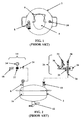
- FIGS. 1 and 2 illustrate a prior art system, illustrated in FIGS. 1 and 2 , is offered by Veltek Associates, Inc. under the name Core2Clean®.
- the unit includes a re-sealable pressure vessel 2 for storing cleaning solutions, such as disinfectant, therein so as to protect the cleaning solution from contaminants when the unit is being used in a cleaning operation.
- the vessel 2 can be un-sealed by removing a vessel lid 4, at which point a cleaning solution may be placed in or removed from the vessel 2.
- the vessel 2 is autoclavable inside and out in the un-sealed configuration. After cleaning solution is placed in the vessel 2, it can be sealed from external contaminants by installing the vessel lid 4.
- Cleaning solution can be dispensed from the sealed vessel 2 via the sprayer, sponge mop or fogger on an as-needed basis, thereby eliminating contamination due to the need to change dirty cleaning solutions during cleanroom washing, which also reduces the total volume of cleaning solution required to perform a cleaning operation.
- the system is operated by compressed gas, such as compressed air.
- compressed air in a pressure vessel 2 creates many potential dangers arising from a potential sudden release of the pressure. Accordingly, safe operation of such a system requires implementation of various pressure regulating devices.
- the prior art system includes a pressure vessel 2 having a vessel lid 4, a handle 6, a first connection point 8, and a second connection point 10.
- the vessel lid 4 can be removed to access the inside of the vessel 2 to add or remove contents, such as cleaning solutions.
- the vessel lid 4 maintains an airtight seal in the vessel 2 when installed.
- the handle 6 is used to facilitate removal and installation of the vessel lid 4.
- the prior art system also includes a drain valve 12, an outlet regulator assembly 14, and an inlet regulator assembly 26.
- the drain valve 12 is located substantially at the bottom of the vessel 2 and is used to drain cleaning and rinsing solutions out of the vessel 2 when the vessel 2 is being cleaned.
- the outlet regulator assembly 14 is installed at the first connection point 8 and is used to dispense cleaning solution from the vessel using a cleaning applicator, such as a sprayer, sponge mop or fogger.
- the inlet regulator assembly 26 is installed at the second connection point 10 and is used to charge the vessel 2 with air pressure.
- the outlet regulator assembly 14 and the inlet regulator assembly 26 are removable from the vessel 2 so the vessel 2 may be properly autoclaved.
- the first connection point 8 includes a dip tube assembly 16 that is in fluid communication with the bottom of the vessel 2 so that cleaning solution can be extracted therefrom. Because only the first connection point 8 includes a dip tube assembly 16 for extracting fluids from the bottom of the vessel 2, the outlet regulator assembly 14 and the inlet regulator assembly 26 cannot be interchangeably installed on the first connection point 8 and the second connection point 10. Accordingly, the outlet regulator assembly 14 can only be installed at the first connection point 8. Further, both the first connection point 8 and the second connection point 10 include internal check-type valves that are in the closed position to prevent fluid communication between the inside of the vessel 2 and the outside of the vessel 2 when the outlet regulator assembly 14 and the inlet regulator assembly 26 are not respectively installed therein.
- fluid communication includes a path by which liquids or gases may move between two or more structures.
- gas communication includes a path by which gases, such as air or steam, may move between two or more structures.
- air and gas are used interchangeably, unless otherwise apparent from the context.
- the outlet regulator assembly 14 of the prior art system includes an outlet connector 18, an inlet connector 20, an outlet manual control valve 22, and an outlet pressure gauge 24.
- cleaning applicators such as a sprayer, sponge mop and fogger
- the outlet regulator assembly 14 is then installed on the vessel 2 at the first connection point 8 via the inlet connector 20 of the outlet regulator assembly 14.
- a user may manually adjust the pressure with which the cleaning solution is dispensed from the vessel 2 by opening or closing the outlet manual control valve 22 as required until the desired pressure is observed on the outlet pressure gauge 24. Charging the vessel 2 is described in more detail below with reference to the inlet regulator assembly 26.
- the inlet regulator assembly 26 of the prior art system includes an outlet connector 28, an inlet connector 30, an inlet manual control valve 32, a relief valve 34, an inlet pressure gauge 36, and a manual purge valve 38.
- the inlet regulator assembly 26 is installed on the vessel 2 at the second connection point 8 via the outlet connector 28 of the inlet regulator assembly 26.
- a charging device (not shown), such as a pressurized tank or line, is then installed at the inlet connector 30 of the inlet regulator assembly 26.
- the user must then open the inlet manual control valve 32 to allow air pressure in the charging device to be transferred into the vessel 2.
- the user must manually adjust the air pressure in the vessel 2 by opening or closing the inlet manual control valve 32 as required until the desired pressure is observed on the inlet pressure gauge 36.
- the relief valve 34 will release some of the air pressure to prevent the air pressure within the vessel 2 from exceeding the predetermined value. Excess pressure can be released from the vessel 2 in this manner, however, only when the inlet regulator assembly 26 is installed on the vessel 2. There are no means by which to relieve excess pressure from the vessel 2 when the inlet regulator assembly 26 is not installed on the vessel 2.
- the inlet regulator assembly 26 of the prior art system is also used to purge the vessel 2 of air to remove any pressure within the vessel 2.
- the vessel 2 may need to be purged, for example, before checking or servicing any part of the system, before loosening or removing the vessel lid 4, or after the user has concluded use of the system.
- the inlet regulator assembly 26 must be installed on the vessel 2 at the second connection point 10 via the outlet connector 28 of the inlet regulator assembly 26.
- the inlet manual control valve 32 To purge the prior art system while the charging device installed at the inlet connector 30 of the inlet regulator assembly 26, the inlet manual control valve 32 must be in the closed position so that air from the charging device is not continuously supplied to the vessel 2, thereby preventing proper purging.
- the inlet manual control valve 32 includes an orifice that is in fluid communication with the outside of the vessel 2 when the inlet manual control valve 32 is closed. Accordingly, air may escape form the vessel 2 via the orifice when the inlet manual control valve 32 is closed, thereby purging the vessel 2.
- the vessel 2 is therefore purged by closing the inlet manual control valve 32 if the charging device is installed in the inlet regulator assembly 26.
- the manual purge valve 38 may also be opened in this configuration to allow air within the vessel to escape therethrough, the manual purge valve 38 thereby operating simultaneously with the orifice of the inlet manual control valve 32 to purge the vessel.
- the prior art system is more likely to be purged with the charging device removed from the inlet connector 30 of the inlet regulator assembly 26.
- the inlet manual control valve 32 may be in the open or closed position.
- the vessel 2 may be purged by placing the inlet manual control valve 32 in the closed position, thereby allowing air within the vessel 2 to escape through the orifice in the inlet manual control valve 32.
- the manual purge valve 38 may also be opened in this configuration to allow air within the vessel to escape therethrough, the manual purge valve 38 thereby operating simultaneously with the orifice of the inlet manual control valve 32 to purge the vessel.
- the vessel may also be purged by placing the inlet manual control valve 32 in the open position.
- the manual purge valve 38 is opened to allow air to escape from the vessel 2 when the inlet manual control valve 32 is in the open position, thereby purging the vessel 2.
- a manual purge valve 38 and inlet pressure gauge 36 must be disposed on the inlet regulator assembly 26 to purge the system. Accordingly, the inlet regulator assembly 26 must be installed on the vessel 2 of the prior art system to purge that system. This is not only an unnecessarily complicated configuration, it also poses certain safety risks.
- the subject valve(s) remain open until the user observes a pressure of zero (0) psi on the inlet pressure gauge 36 and can no longer hear air escaping the vessel 2.
- the inlet regulator assembly 26 is removed from the vessel 2 to allow the vessel 2 to be sterilized by a process such as autoclaving.
- Autoclaving includes utilizing high temperature steam in a sterilization process.
- the vessel lid 4 To autoclave the vessel, the vessel lid 4 must be removed and the drain valve 12 is opened to allow steam to pass through the vessel 2.
- the outlet regulator assembly 14 and the inlet regulator assembly 26 are removed from the vessel 2 during autoclaving because they are not autoclavable.
- the outlet regulator assembly 14 and the inlet regulator assembly 26 are not autoclavable because they are not configured to allow steam to pass therethrough and because their respective components 18-24 and 28-38 are not designed to withstand the high temperatures associated with autoclaving.
- the outlet connector 18, inlet connector 20, outlet manual control valve 22, and outlet pressure gauge 24 of the outlet regulator assembly 14 and the outlet connector 28, inlet connector 30, inlet manual control valve 32, relief valve 34, inlet pressure gauge 36, and manual purge valve 38 of the inlet regulator assembly 26 are all not autoclavable.
- an autoclavable bucketless cleaning system that includes an autoclavable vessel with an inside for storing fluid under pressure and with a first connection point and a second connection point disposed at an outside of the vessel, an autoclavable outlet regulator assembly for dispensing fluid from the vessel and removably connected to the vessel at the first connection point so as to be in fluid communication with the inside of the vessel, and an autoclavable inlet regulator assembly for pressurizing the vessel and removably connected to the vessel at the second connection point to be in fluid communication with the inside of the vessel.
- It is another non-limiting object of the present invention to provide a method of performing a cleaning operation with an autoclavable bucketless cleaning system that includes placing a cleaning solution in an inside of an autoclavable vessel where the vessel includes a first connection point and a second connection point disposed at an outside of the vessel, removably connecting an autoclavable outlet regulator assembly on the vessel at the first connection point so the outlet regulator assembly is in fluid communication with the inside of the vessel, removably connecting an autoclavable inlet regulator assembly on the vessel at the second connection point so the inlet regulator assembly is in fluid communication with the inside of the vessel, pressurizing the inside of the vessel via the inlet regulator assembly, dispensing cleaning solution from the inside of the vessel via the outlet regulator assembly to clean a designated area, removing any pressurized gas that remains inside the vessel after the designated area is cleaned, removing any cleaning solution that remains inside the vessel after the designated area is cleaned, and autoclaving each of the vessel, the outlet regulator assembly, and the inlet regulator assembly.
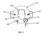
- FIG. 3 shows a top view illustrating a non-limiting embodiment of the autoclavable bucketless cleanroom washing system 100 of the present invention.
- the system 100 includes a re-sealable pressure vessel 102 having a vessel lid 104, a handle 106, a relief valve 108, a manual purge valve 110, a vessel pressure gauge 112, a first connection point 114, and a second connection point 116.
- the vessel lid 104 can be removed to access the inside of the vessel 102 to add or remove contents, such as cleaning solutions.
- the vessel lid 104 maintains an airtight seal in the vessel 102 when installed.
- the handle 106 is used to facilitate removal and installation of the vessel lid 104.
- the relief valve 108 automatically opens to relieve pressure from the vessel 102 when the pressure therein exceeds a predetermined value, for example 90 psi.
- the manual purge valve 110 is used to purge the vessel 102 of pressurized gas to remove any pressure inside the vessel 102.
- the vessel may need to be purged, for example, before checking or servicing any part of the system, before loosening or removing the vessel lid 104, or after the user has concluded use of the system.
- the vessel pressure gauge 112 allows a user to observe the pressure within the vessel 102 at all times.
- the vessel lid 104 includes a handle 106 disposed thereon for removing and installing the vessel lid 104 on the vessel 102.
- the vessel lid 104 is sealably installed at the top of the vessel 102 with edges at the perimeter of the vessel lid 104 engaging corresponding edges in an opening at the top of the vessel 102 so as to create an airtight enclosure within the vessel 102 when installed.
- the airtight seal created by installing the vessel lid 104 in the vessel 102 allows fluids to be stored inside the vessel 102 and placed under pressure.
- the vessel lid 104 may be removed so that fluids can be placed in the vessel 102 through the opening at the top of the vessel 102.
- the vessel 102 is ASME rated to at least 90 psi when sealed.
- the relief valve 108 remains closed until the pressure inside the vessel 102 exceeds a predetermined value, at which point the valve automatically opens to allow pressurized gas inside the vessel 102 to escape until the pressure inside the vessel 102 is at or below the predetermined value.
- the relief valve 108 is connectably disposed in the top of the vessel 102 and is in direct gas communication with the inside thereof.
- the relief valve 108 is normally in the closed position so that there is not gas communication between the inside of the vessel 102 and the outside of the vessel 102 via the relief valve 108.
- the relief valve 108 will open to allow gas communication between the inside of the vessel 102 and the outside of the vessel 102.
- the relief valve 108 may be preset to open at any pressure value above the pressure value that the vessel 102 is rated to safely contain, such as 90 psi.
- the relief valve 108 may also include an exhaust tube connected thereto for directing any gas released from the relief valve 108 away from a user of the system 100.
- the manual purge valve 110 is manually opened and closed. As illustrated in the exemplary embodiment of FIG. 4 , the manual purge valve 110 is disposed at the top of the vessel 102 with a vessel pressure gauge 112 connectably disposed between the manual purge valve 110 and the vessel 102.
- the manual purge valve 110 and vessel pressure gauge 112 are in gas communication with the inside of the vessel 102 and with each other.
- the manual purge valve may be connectably disposed in the top of the vessel 102 at one location so as to be in direct gas communication with the inside of the vessel 102
- the vessel pressure gauge may be connectably disposed directly in the top of the vessel 102 in another location so as to be in direct gas communication with the inside of the vessel 102.
- the vessel pressure gauge 112 measures and displays the pressure within the vessel 102.
- the manual purge valve 110 is normally in the closed position so that there is not gas communication between the inside of the vessel 102 and the outside of the vessel 102 via the manual purge valve 110. Because it is disposed between the manual purge valve 110 and the vessel 102, the vessel pressure gauge 112 is in direct gas communication with the inside of the vessel 102 even when the manual purge valve 110 is in the closed position. Thus, the vessel pressure gauge 112 continuously measures and displays the pressure within the vessel 102 regardless of whether the manual purge valve 110 is in the open or closed position and whether the outlet regulator assembly 120 and/or the inlet regulator assembly 136 are installed on the vessel 102.
- the manual purge valve 110 can be opened to reduce or remove pressure in the vessel 102, a process generally referred to as "purging" the vessel 102.
- the manual purge valve 110 may also include an exhaust tube connected thereto for directing any gas being released from the manual valve 110 away from a user of the system 100.
- the system 100 also includes a drain valve 118, an outlet regulator assembly 120, and an inlet regulator assembly 136.
- the drain valve 118 is located substantially at the bottom of the vessel 102 and is used to drain the vessel 102 when the vessel 102 is cleaned.
- the outlet regulator assembly 120 is installed at the first connection point 114 and is used to dispense cleaning solution from the vessel using a cleaning applicator, such as a sprayer 152, sponge mop 154 or fogger (not shown).
- the inlet regulator assembly 136 is installed at the second connection point 116 and is used to charge the vessel 102 with gas to a predetermined pressure value.
- the first connection point 114 includes a dip tube assembly 122 that is in fluid communication with the bottom of the vessel 102 so that cleaning solution can be extracted therefrom. Because only the first connection point 114 includes a dip tube assembly 122 for extracting fluids from the bottom of the vessel 102, the outlet regulator assembly 120 and the inlet regulator assembly 136 may not be interchangeably installed on the first connection point 114 and the second connection point 116. Accordingly, the outlet regulator assembly 120 may only be installed at the first connection point 114. Further, both the first connection point 114 and the second connection point 116 include internal check-type valves that are in the closed position to prevent fluid communication between the inside of the vessel 102 and the outside of the vessel 102 when the outlet regulator assembly 120 and the inlet regulator assembly 136 are not respectively installed therein.
- the check-valve in the first connection point 114 is opened so as to allow fluid communication between the vessel 102 and the outlet regulator assembly 120.
- the outlet connector 140 of the inlet regulator assembly 136 is installed at the second connection point 116, the check-valve in the second connection point 116 is opened so as to allow fluid communication between the vessel 102 and the inlet regulator assembly 136.
- the first connection point 114 may be keyed to only receive the inlet connector 126 of the outlet regulator assembly 120 to prevent mistakenly installing the outlet regulator assembly 120 at the second connection point 116 or installing the inlet regulator assembly 136 at the first connection point 114.
- the first connection point 114 and the second connection point 116 may be of different sizes to prevent mistakenly installing the outlet regulator assembly 120 at the second connection point 116 or installing the inlet regulator assembly 136 at the first connection point 114.
- the outlet regulator assembly 120 of the system 100 includes an outlet connector 124, an inlet connector 126, an outlet metering valve 128, an outlet pressure gauge 130, an outlet autoclave stem 132, and a lanyard 134.
- the outlet connector 124 is disposed at one end of the outlet regulator assembly 120 and the inlet connector 126 is disposed at the other end of the outlet regulator assembly 120.
- the outlet metering valve 128 and the outlet pressure gauge 130 are positioned between the outlet connector 124 and the inlet connector 126.
- the outlet metering valve 128 is positioned adjacent to the inlet connector 126 and the outlet pressure gauge 130 is positioned between the outlet connector 124 and the outlet metering valve 128.
- outlet connector 124, inlet connector 126, outlet metering valve 128, and outlet pressure gauge 130 are connectably joined so that each member of the outlet regulator assembly 120 is in fluid communication with each other member.
- the outlet pressure gauge 130 measures and displays the pressure between the outlet metering valve 128 and the outlet connector 124.
- the outlet metering valve 128 is manually opened and closed using a flow control element, e.g., a valve handle, such that each incremental adjustment of the flow control element produces a substantially proportional change of the mass flow rate through the outlet metering valve 128.
- the outlet metering valve 128 of the present system 100 differs from the outlet manual control valve 22 of the prior art system because it allows more accurate control of flow rates.
- the outlet metering valve 128 of the outlet regulator assembly 120 is opened to allow fluid communication between the outlet connector 124 and the inlet connector 126 and closed to prevent fluid communication between the outlet connector 124 and the inlet connector 126, i.e., to stop cleaning solution from being dispensed from the vessel 102 via the outlet regulator assembly 120.
- the outlet metering valve 128 may be partially opened such that the amount of fluid communication between the outlet connector 124 and the inlet connector 126 corresponds to the amount the outlet metering valve 128 is opened, with a larger opening corresponding to a larger amount of fluid communication.
- the outlet connector 124 of the outlet regulator assembly 120 is a female quick disconnect that includes an internal check-type valve configured to be in the closed position when not connected to a corresponding male quick disconnect or autoclave stem.
- the inlet connector 126 of the outlet regulator assembly 120 is a male quick disconnect that is configured to be open at all times. Accordingly, when a corresponding male quick disconnect or autoclave stem is not installed at the outlet connector 126, there is no fluid communication through the outlet regulator assembly 120 due to the closed check-type valve in the outlet connector 124, i.e., fluid can enter the outlet regulator assembly 120 via the inlet connector 126 but it cannot exit the outlet regulator assembly 120 via the outlet connector 124, regardless of whether the outlet metering valve 128 is opened.
- the outlet autoclave stem 132 mates with the outlet connector 124 of the outlet regulator assembly 120 so as to open the check-type valve in the outlet connector 124. This allows steam to pass through the outlet regulator assembly 120 during autoclaving, i.e., into the inlet connector 126 and out of the outlet connector 124.
- the outlet autoclave stem 132 is attached to the outlet regulator assembly 120 with the lanyard 134 so that the outlet autoclave stem 132 is not misplaced from the outlet regulator assembly 120 when not in use.
- the inlet regulator assembly 136 of the system 100 includes an inlet connector 138, an outlet connector 140, a regulator valve 142, an inlet autoclave stem 144, and a lanyard 146.
- the inlet connector 138 is disposed at one end of the inlet regulator assembly 136 and the outlet connector 140 is disposed at the other end of the inlet regulator assembly 136.
- the regulator valve 142 is positioned between the inlet connector 138 and the outlet connector 140.
- the inlet connector 138, outlet connector 140, and regulator valve 142 are connectably joined so that each member of the inlet regulator assembly 136 is in fluid communication with each other member.
- the regulator valve 142 remains open until the pressure inside the vessel 102 reaches a predetermined value, at which point the valve automatically closes to prevent more gas from entering the vessel 102, thereby preventing the pressure of the gas in the vessel 102 from rising to a dangerous value, i.e., above the pressure value that the vessel 102 is rated to contain.
- the regulator valve 142 of the inlet regulator assembly 136 is open to allow fluid communication between the inlet connector 138 and the outlet connector 140 until the pressure inside the vessel 102 reaches a predetermined value, at which point the regulator valve 142 will close to prevent fluid communication between the inlet connector 138 and the outlet connector 140.
- the regulator valve 142 is preset to close at a pressure value at or below the pressure value that the vessel 102 is rated to safely contain.
- the regulator valve 142 is used to fill the vessel 102 with pressurized gas, such as pressurized air. This process is generally referred to as "charging" the vessel 102.
- the inlet connector 138 of the inlet regulator assembly 136 is a female quick disconnect that includes an internal check-type valve configured to be in the closed position when not connected to a corresponding male quick disconnect or autoclave stem.
- the outlet connector 140 of the inlet regulator assembly 136 is a male quick disconnect that is configured to be open at all times.
- the regulator valve 142 may also prevent fluid from exiting the inlet regulator assembly 136 via the inlet connector 138 by being configured to function as a directional-type valve in addition to functioning as a regulator valve, thereby allowing fluid to flow through the inlet regulator assembly 142 only in a direction from the inlet connector 138 to the outlet connector 140.
- the inlet autoclave stem 144 mates with the inlet connector 138 of the inlet regulator assembly 136 so as to open the check-type valve in the inlet connector 138.
- the inlet autoclave stem 144 is connected at the inlet connector 13 8 to allow steam to pass through the inlet regulator assembly 136 during autoclaving, i.e., into the inlet connector 138 and out of the outlet connector 140.
- the inlet autoclave stem 144 may be attached to the inlet regulator assembly 136 with the lanyard 146 so that the inlet autoclave stem 144 is not misplaced from the inlet regulator assembly 136 when not in use.
- the above-described components of the system 100 may be utilized together to perform a cleaning operation of a cleanroom.
- An exemplary embodiment of a method in which the system 100 may be utilized in a cleaning operation is described hereinafter with reference to FIGS. 3 and 4 .
- the method includes filling the vessel 102 with a cleaning solution and sealing the vessel 102; connecting a cleaning applicator to the outlet regulator assembly 120 and installing the outlet regulator 120 on the vessel 102; installing the inlet regulator 136 on the vessel 102 and connecting a charging device to the inlet regulator 136; placing a charge on the vessel 102; dispensing the cleaning solution using the cleaning applicator; purging the vessel 102 after dispensing the cleaning solution is completed; draining and rinsing the system; and autoclaving the entire system 100 after the vessel 102 has been purged.
- These functions and the order in which they are performed are exemplary and non-limiting, but are chosen as a preferred method for safe and efficient operation of the system 100.
- the vessel lid 104 is removed using the handle 106. Before removing the vessel lid 104, ensure the vessel 102 has been purged as discussed below using the manual purge valve 110. A predetermined amount of cleaning fluid is then placed inside the vessel 102 via an opening in the top thereof. After cleaning solution is placed in the vessel 102, the vessel lid 104 is sealably installed in the vessel 102 so as to create an airtight chamber within the vessel 102 that includes the cleaning solution.
- a cleaning applicator is connected to the outlet regulator assembly 120 at the outlet connector 124.
- the cleaning applicator may be connected to the outlet regulator assembly 120 using an extension piece 148, such as a high pressure coil hose assembly.
- the outlet autoclave stem 132 is not installed in the outlet connector 124 when the cleaning applicator is connected to the outlet regulator assembly 120 because a connection cannot be made with the outlet connector 124 when the outlet autoclave stem 132 is installed.
- the outlet regulator assembly 120 is then installed on the vessel 102 at the first connection point 114 via the inlet connector 126 of the outlet regulator assembly 120.
- a charge may be placed on the vessel 102.
- a charge is preferably not placed on the vessel 102 until after the outlet regulator assembly 120 is installed on the vessel 102 because making the above connections can be more difficult when the system is pressurized.
- the inlet regulator assembly 136 is installed on the vessel 102 at the second connection point 116 via the outlet connector 140 of the inlet regulator assembly 136.
- a charging device (not shown), such as a pressurized tank, is then connected to the inlet connector 138 of the inlet regulator assembly 136.
- the charging device may be connected to the inlet regulator assembly 136 using a charging hose 150, such as a high pressure coil hose assembly.
- the charging hose 150 is connected to the inlet regulator assembly 136 only after the inlet regulator assembly 136 is installed in the vessel 102 because the connection between the inlet regulator assembly 136 and the vessel 102 can more difficult to make when there is pressure within the inlet regulator assembly 136.
- the inlet autoclave stem 144 is not installed in the inlet connector 138 when the charging hose 150 is connected to the inlet regulator assembly 136 because a connection cannot be made with the inlet connector 138 when the inlet autoclave stem 144 is installed.
- the vessel 102 When the charging hose 150 is installed in the inlet regulator assembly 136, the vessel 102 will automatically receive a predetermined amount of pressurized gas from the charging hose 150 until the pressure in the vessel 102 reaches a predetermined value, the predetermined value of pressure corresponding to the pressure at which the regulator valve 142 is set to close. Thus, a user just connects the charging hose 150 to the inlet regulator assembly 136 and the regulator valve 142 closes when the pressure inside the vessel 102 reaches the desired predetermined pressure value.
- the regulator valve 142 is set to close at 90 psi.
- the relief valve 108 disposed in the vessel 102 will open before the pressure reaches an unsafe value, thereby providing an extra level of safety in the system.
- a user is protected from charging the vessel 102 to an unsafe pressure if the user bypasses the inlet regulator assembly 136.
- the relief valve 108 provides a direct and immediate safety check on the pressure inside the vessel 102.
- the cleaning solution can be dispensed from the vessel using the cleaning applicator that is connected to the outlet regulator assembly 120.
- the outlet metering valve 128 is opened until the desired dispensing pressure is obtained.
- Flow rate and particle size of the cleaning solution dispensed from the system 100 are adjusted by opening or closing the outlet metering valve 128 as required until the desired pressure is observed on the outlet pressure gauge 130.
- the outlet metering valve 128 is adjustable between 0 (zero) and 60 psi.
- the flow rate at which the cleaning solution is dispensed from the vessel 102 can be determined using a chart listing various flow rates that correspond to valve handle positions of the outlet metering valve 128.
- the chart is based on the valve handle position and the pressure drop across the outlet metering valve 128.
- the position of the valve handle corresponds to the cross-sectional area of flow through the outlet metering valve 128.
- the pressure drop across the valve is measured by subtracting the pressure observed on the outlet pressure gauge 130 from the pressure observed on the vessel pressure gauge 112.
- the outlet metering valve 128 allows a user of the system 100 to accurately measure the volume of cleaning solution dispensed over a specific duration of a cleaning operation.
- the user may determine the volume of cleaning solution dispensed during a cleaning operation. This allows the user to accurately and conveniently determine how much fluid to place in the vessel 102 based on how long a cleaning operation is estimated to take.
- the flow rate at which the cleaning solution is dispensed from the vessel 102 can also be determined using a chart listing the various flow rates produced based on the pressure with which fluid is dispensed and the size of the orifice of the cleaning applicator attached to the outlet regulator assembly 120.
- the pressure with which fluid is dispensed is observed on the outlet pressure gauge 130, and the orifice size may be predetermined or variable depending on the type of cleaning applicator used. Accordingly, by changing orifice sizes on the cleaning applicator and adjusting the pressure with which fluid is dispensed via the outlet metering valve 128, the user may determine the volume of cleaning solution dispensed during a cleaning operation. This allows the user to more accurately and conveniently determine how much fluid to place in the vessel 102 based on how long a cleaning operation is estimated to take.
- the particle size at which the cleaning solution is dispensed from the vessel 102 can be determined using a chart listing the various particle sizes produced based on the pressure with which fluid is dispensed and the size of the orifice of the cleaning applicator, for example a sprayer 152 or a fogger.
- the dispensing pressure is observed on the outlet pressure gauge 130. Accordingly, by varying orifice sizes on the sprayer 152 or fogger and adjusting pressure via the outlet metering valve 128, various particle sizes can be produced using the sprayer 152 or fogger.
- cleaning applicators such as a sprayer 152, sponge mop 154 and/or fogger
- the amount of cleaning solution dispensed can also be controlled using a standard trigger spray wand 156.
- the spray wand may be connected to the outlet regulator assembly via an extension hose 148.
- the sprayer 152, sponge mop 154 or fogger may be interchangeably connected at the end of the extension hose 148 or the spray wand 156 via quick disconnect connections.
- the amount of cleaning solution dispensed is controlled by adjusting the outlet metering valve 128 as discussed above with respect to flow rates.
- the spray wand 156 adds an extra element of control by allowing the user to dispense cleaning solution by squeezing a trigger on the spray wand 156 and to stop the dispensing of cleaning solution by releasing the trigger of the spray wand 156. This added element of control over the amount of cleaning solution dispensed further increases the efficiency of the system 100.
- the outlet metering valve 128 8 may be adjusted so that cleaning solution is dispensed at a desired pressure of 30 psi, as observed on the outlet pressure gauge 130.
- the outlet metering valve 128 may be adjusted so that cleaning solution is dispensed at a desired pressure of 25 psi, as observed on the outlet pressure gauge 130.
- the cleaning solution may be dispensed with a particle size between 5 and 50 microns.
- pressure is manually relieved, or purged, from the system 100.
- Pressure is purged from the vessel 102 via the manual purge valve 110 disposed on the vessel 102.
- the manual purge valve 110 is opened and remains open until a pressure of 0 (zero) psi is observed on the vessel pressure gauge 112 and gas can no longer be heard escaping the vessel 102 through the manual purge valve 110.
- the vessel cannot be purged from the outlet regulator assembly 120 because there is a dip tube assembly 122 attached to the first connection point 114 that is in fluid communication with the bottom of the vessel 102 such that purging the vessel 102 at this location would result in expelling cleaning solution that may remain in the vessel 102.
- the vessel 102 can be purged without the inlet regulator assembly 136 being installed. This not only simplifies the purging process, but it makes the system 100 safer.
- the vessel 102 can be purged at any time because the manual purge valve 110 and vessel pressure gauge 112 are disposed directly on the vessel 102 rather than on the inlet regulator assembly 136. This is of particular importance since the vessel 102 should be purged whenever the vessel lid 104 is to be removed. There may also be other circumstances in which the pressure within the vessel needs to be purged.
- the vessel 102 may be rinsed.
- the vessel 102 is rinsed by removing the vessel lid 104 and placing the appropriate rinsing solutions in the vessel 102.
- the drain valve 118 is opened to allow the rinsing solution to exit the vessel 102.
- the system 100 may also be charged and the rinsing solution dispensed through the sprayer, sponge mop and/or fogger as described above to rinse those components as well.
- all of the components of the system may be autoclaved, including the vessel 102 and its integrated components, the entire outlet regulator assembly 120, the entire inlet regulator assembly 136, the extension pieces 148 and 150, the sprayer 152, the sponge mop 154, the fogger, and the spray wand 156.
- the integrated components of the vessel 102 include the vessel lid 104, the handle 106, the relief valve 108, the manual purge valve 110, the vessel pressure gauge 112, the first connection point 114, the second connection point 116, and the drain valve 118.
- the "entire" autoclavable outlet regulator assembly 120 includes the outlet connector 124, the inlet connector 126, the outlet metering valve 128, the outlet pressure gauge 130, the outlet autoclave stem 132, and the lanyard 134.
- the "entire" autoclavable inlet regulator assembly 136 includes the inlet connector 138, the outlet connector 140, the regulator valve 142, the inlet autoclave stem 144, and the lanyard 146.
- the outlet regulator assembly 120 and the inlet regulator assembly 136 may be installed on the vessel 102 when the system 100 is autoclaved.
- the vessel lid 104 Prior to autoclaving the vessel 102 and vessel's integrated components 104-118 with the entire outlet regulator assembly 120 and the entire inlet regulator assembly 136 installed on the vessel 102, the vessel lid 104 is removed from the vessel 102 and the drain valve 118 8 is opened so that steam may pass through the vessel 102 during autoclaving.
- the outlet autoclave stem 132 is installed at the outlet connector 124 of the outlet regulator assembly 120 to open the internal check-valve of the outlet connector 124 so that steam may pass through the outlet regulator assembly 120 during autoclaving.
- the outlet metering valve 128 is also opened.
- the inlet autoclave stem 144 is installed at the inlet connector 138 of the inlet regulator assembly 136 to open the internal check-valve of the inlet connector 138 so that steam may pass through the inlet regulator assembly 136 during autoclaving.
- the inlet regulator valve 142 is automatically opened when the vessel 102 is purged and will remain open during autoclaving.
- the vessel pressure gauge 112 may be sprayed to saturation with a sterilizing compound, for example, Sterile 70% USP Isopropyl Alcohol, prior to introducing it into the autoclave so as to further ensure sterilization thereof.
- the outlet regulator assembly 120 and the inlet regulator assembly 136 may be removed from the vessel 102 and autoclaved separate from the vessel 102.
- autoclave stems (not shown) are installed in the first connection point 114 and the second connection point 116 of the vessel 102 to open the internal check-valves therein so that steam may pass through the first connection point 114 and the second connection point 116 during autoclaving.
- Autoclave stems 132 and 144 are also installed in the outlet regulator assembly 120 and the inlet regulator assembly 136.
- the internal check-valves of the first connection point 114 and the second connection point 116 are opened respectively by the inlet connector 126 of the outlet regulator assembly 120 and the outlet connector 140 of the inlet regulator assembly 136.
- the entire system 100 may be autoclaved, including the vessel 102, the vessel's integrated components 104-118, the entire outlet regulator assembly 120, the entire inlet regulator assembly 136, the extension pieces 148 and 150, the sprayer 152, the sponge mop 154, the fogger, and the spray wand 156.
- Autoclaving includes utilizing steam in a sterilization process.
- the entire system 100 may be placed in an autoclaving device, such as a machine capable of achieving elevated temperatures and pressures, to sterilize all of the components 102-156 of the system 100.
- the system may be autoclaved, for example, at 121°C for 35 minutes.
- the system 100 of the present invention is reliable and provides substantial control over contaminants by allowing all of the components to be autoclaved.
- each of the relief 108, the manual purge valve 110, the vessel pressure gauge 112, the outlet regulator assembly 120, and the inlet regulator assembly 136 have separate and distinct benefits that contribute to the reliability and control of the present system 100. Accordingly, each of these components can be used alone or in any combination thereof to achieve the same or similar benefits.
Landscapes
- Health & Medical Sciences (AREA)
- Epidemiology (AREA)
- Life Sciences & Earth Sciences (AREA)
- Animal Behavior & Ethology (AREA)
- General Health & Medical Sciences (AREA)
- Public Health (AREA)
- Veterinary Medicine (AREA)
- Chemical Kinetics & Catalysis (AREA)
- Chemical & Material Sciences (AREA)
- General Chemical & Material Sciences (AREA)
- Engineering & Computer Science (AREA)
- Mechanical Engineering (AREA)
- Cleaning In General (AREA)
- Cleaning By Liquid Or Steam (AREA)
- Filling Or Discharging Of Gas Storage Vessels (AREA)
- Apparatus For Disinfection Or Sterilisation (AREA)
- Quick-Acting Or Multi-Walled Pipe Joints (AREA)
Priority Applications (1)
| Application Number | Priority Date | Filing Date | Title |
|---|---|---|---|
| EP20130180046 EP2664389B1 (de) | 2008-02-19 | 2008-08-21 | Autoklavierbares eimerloses Reinigungssystem und Verfahren damit |
Applications Claiming Priority (1)
| Application Number | Priority Date | Filing Date | Title |
|---|---|---|---|
| US12/033,719 US20090208367A1 (en) | 2008-02-19 | 2008-02-19 | Autoclavable bucketless cleaning system |
Related Child Applications (2)
| Application Number | Title | Priority Date | Filing Date |
|---|---|---|---|
| EP20130180046 Division EP2664389B1 (de) | 2008-02-19 | 2008-08-21 | Autoklavierbares eimerloses Reinigungssystem und Verfahren damit |
| EP13180046.8 Division-Into | 2013-08-12 |
Publications (3)
| Publication Number | Publication Date |
|---|---|
| EP2092990A2 true EP2092990A2 (de) | 2009-08-26 |
| EP2092990A3 EP2092990A3 (de) | 2012-05-02 |
| EP2092990B1 EP2092990B1 (de) | 2013-09-18 |
Family
ID=40637021
Family Applications (2)
| Application Number | Title | Priority Date | Filing Date |
|---|---|---|---|
| EP20130180046 Active EP2664389B1 (de) | 2008-02-19 | 2008-08-21 | Autoklavierbares eimerloses Reinigungssystem und Verfahren damit |
| EP20080162720 Active EP2092990B1 (de) | 2008-02-19 | 2008-08-21 | Reinigungsverfahren mit einem autoklavierbaren eimerlosen Reinigungssystem |
Family Applications Before (1)
| Application Number | Title | Priority Date | Filing Date |
|---|---|---|---|
| EP20130180046 Active EP2664389B1 (de) | 2008-02-19 | 2008-08-21 | Autoklavierbares eimerloses Reinigungssystem und Verfahren damit |
Country Status (6)
| Country | Link |
|---|---|
| US (8) | US20090208367A1 (de) |
| EP (2) | EP2664389B1 (de) |
| CN (2) | CN104624587B (de) |
| ES (2) | ES2435441T3 (de) |
| SG (1) | SG155108A1 (de) |
| WO (1) | WO2009108475A2 (de) |
Cited By (1)
| Publication number | Priority date | Publication date | Assignee | Title |
|---|---|---|---|---|
| US12083562B2 (en) | 2008-02-19 | 2024-09-10 | Veltek Associates, Inc. | Pressurized cleaning system |
Families Citing this family (28)
| Publication number | Priority date | Publication date | Assignee | Title |
|---|---|---|---|---|
| EP2153157A4 (de) | 2007-05-11 | 2014-02-26 | Sdcmaterials Inc | Wasserkühlsystem und wärmeübertragungssystem |
| US8480011B2 (en) | 2007-09-04 | 2013-07-09 | Dehn's Innovations, Llc | Nozzle system and method |
| US8507401B1 (en) | 2007-10-15 | 2013-08-13 | SDCmaterials, Inc. | Method and system for forming plug and play metal catalysts |
| US8557727B2 (en) | 2009-12-15 | 2013-10-15 | SDCmaterials, Inc. | Method of forming a catalyst with inhibited mobility of nano-active material |
| US9126191B2 (en) | 2009-12-15 | 2015-09-08 | SDCmaterials, Inc. | Advanced catalysts for automotive applications |
| US8803025B2 (en) | 2009-12-15 | 2014-08-12 | SDCmaterials, Inc. | Non-plugging D.C. plasma gun |
| US8652992B2 (en) | 2009-12-15 | 2014-02-18 | SDCmaterials, Inc. | Pinning and affixing nano-active material |
| US9149797B2 (en) | 2009-12-15 | 2015-10-06 | SDCmaterials, Inc. | Catalyst production method and system |
| US9090475B1 (en) | 2009-12-15 | 2015-07-28 | SDCmaterials, Inc. | In situ oxide removal, dispersal and drying for silicon SiO2 |
| USD659925S1 (en) * | 2010-03-25 | 2012-05-15 | Mr. Bar-B-Q-, Inc. | Fountain grill cleaner |
| US8669202B2 (en) | 2011-02-23 | 2014-03-11 | SDCmaterials, Inc. | Wet chemical and plasma methods of forming stable PtPd catalysts |
| MX2014001718A (es) | 2011-08-19 | 2014-03-26 | Sdcmaterials Inc | Sustratos recubiertos para uso en catalisis y convertidores cataliticos y metodos para recubrir sustratos con composiciones de recubrimiento delgado. |
| US10182696B2 (en) * | 2012-09-27 | 2019-01-22 | Dehn's Innovations, Llc | Steam nozzle system and method |
| US9296060B2 (en) * | 2012-11-01 | 2016-03-29 | Michael Hacikyan | Field-customizable inflatable purge dam apparatus |
| US9156025B2 (en) | 2012-11-21 | 2015-10-13 | SDCmaterials, Inc. | Three-way catalytic converter using nanoparticles |
| US9511352B2 (en) | 2012-11-21 | 2016-12-06 | SDCmaterials, Inc. | Three-way catalytic converter using nanoparticles |
| US10562078B2 (en) | 2013-07-01 | 2020-02-18 | Ecp Incorporated | Vacuum spray apparatus and uses thereof |
| US9586179B2 (en) | 2013-07-25 | 2017-03-07 | SDCmaterials, Inc. | Washcoats and coated substrates for catalytic converters and methods of making and using same |
| CN106061600A (zh) | 2013-10-22 | 2016-10-26 | Sdc材料公司 | 用于重型柴油机的催化剂设计 |
| CA2926135A1 (en) | 2013-10-22 | 2015-04-30 | SDCmaterials, Inc. | Compositions of lean nox trap |
| CN106470752A (zh) | 2014-03-21 | 2017-03-01 | Sdc材料公司 | 用于被动nox吸附(pna)系统的组合物 |
| EP3398695A4 (de) * | 2015-12-28 | 2019-10-16 | Positec Power Tools (Suzhou) Co., Ltd | Hochdruckreiniger und verfahren zur identifizierung eines sprühbalkens davon |
| CN106914439B (zh) * | 2015-12-28 | 2021-01-05 | 苏州宝时得电动工具有限公司 | 压力清洗机 |
| JP7116735B2 (ja) * | 2017-02-24 | 2022-08-10 | メルク パテント ゲゼルシャフト ミット ベシュレンクテル ハフツング | 水浄化および配分システムおよび方法 |
| US11931760B2 (en) | 2018-08-14 | 2024-03-19 | Ecp Incorporated | Spray head structure |
| CN112916544B (zh) * | 2019-12-06 | 2022-07-05 | 中国石油天然气股份有限公司 | 凝液缸解堵装置及解堵方法 |
| US10842896B1 (en) | 2020-03-27 | 2020-11-24 | Tech Goods USA Inc. | Device for disinfecting a portable object |
| EP4161705A4 (de) * | 2020-06-09 | 2024-06-26 | Quin Global US, Inc. | Desinfektions- und desinfektionskanistersystem und dosiervorrichtung für system |
Family Cites Families (65)
| Publication number | Priority date | Publication date | Assignee | Title |
|---|---|---|---|---|
| US3076576A (en) * | 1959-07-17 | 1963-02-05 | Cornelius Co | Closure operator |
| US3286884A (en) * | 1965-02-08 | 1966-11-22 | Creative Vending Corp | Portable beverage dispenser |
| US3830632A (en) * | 1969-07-23 | 1974-08-20 | C Guzay | Carbon dioxide absorber apparatus |
| US3759164A (en) | 1971-10-13 | 1973-09-18 | S Robinson | Indoor-outdoor cooker |
| SE403965B (sv) | 1976-01-26 | 1978-09-18 | Electrolux Ab | Sett och anordning vid en steriliseringsautoklav |
| US4114853A (en) | 1976-10-08 | 1978-09-19 | Swagelok Company | Quick connect coupling |
| US4253684A (en) * | 1979-05-14 | 1981-03-03 | Monsanto Company | Quick connect coupler with air shield |
| US4463746A (en) | 1982-08-18 | 1984-08-07 | Unr Industries, Inc. | Portable barbecue grill |
| US4637464A (en) * | 1984-03-22 | 1987-01-20 | Amoco Corporation | In situ retorting of oil shale with pulsed water purge |
| US4898212A (en) | 1984-10-01 | 1990-02-06 | Eaton Corporation | Fatigue resistant hose |
| US4637454A (en) | 1985-04-01 | 1987-01-20 | Mydax, Inc. | Wide range temperature control system for fluids |
| US4889812A (en) * | 1986-05-12 | 1989-12-26 | C. D. Medical, Inc. | Bioreactor apparatus |
| JPS6341853A (ja) | 1986-08-07 | 1988-02-23 | Fuji Photo Film Co Ltd | ハロゲン化銀カラ−写真感光材料 |
| US5277876A (en) | 1987-08-28 | 1994-01-11 | Wagner Gmbh Fabrik Fur Medizinische | Valve apparatus and method for sterilizer container |
| DE3734830A1 (de) * | 1987-10-14 | 1989-04-27 | Gilowy Hans Maschf | Verfahren zur sterilisation von temperaturbelastbaren behaeltern unter reinraumbedingungen |
| US4834293A (en) | 1988-03-23 | 1989-05-30 | Lichfield William H | Spray wand |
| US5045055A (en) * | 1988-10-21 | 1991-09-03 | Den-Tal-Ez, Inc. | Flow control valve assembly for syringes |
| US5016817A (en) * | 1989-11-08 | 1991-05-21 | University Of Georgia Research Foundation, Inc. | Pesticide spraying device and method |
| US5064814A (en) | 1990-04-05 | 1991-11-12 | Rhone-Poulenc Rorer Pharmaceuticals Inc. | Anti-thrombotic peptide and pseudopeptide derivatives |
| JPH0649057A (ja) | 1991-12-04 | 1994-02-22 | Nippon Oil & Fats Co Ltd | トリオキサン誘導体、その製造方法および化学発光方法 |
| US5424046A (en) * | 1992-02-28 | 1995-06-13 | Smith; Benjamin G. | Method and apparatus for steam sterilization |
| US5507065A (en) | 1993-12-10 | 1996-04-16 | Mcbride; John | Cleanroom washing system |
| US5424048A (en) | 1994-03-15 | 1995-06-13 | Riley Medical Inc. | Modular sterilization tray system for medical instruments |
| US5772075A (en) * | 1996-02-14 | 1998-06-30 | Ash, Jr.; William O. | Portable slush beverage dispensing system |
| US5678531A (en) | 1996-03-20 | 1997-10-21 | Byers; Thomas L. | Griddle attachment for outdoor grill |
| US5676531A (en) * | 1996-03-21 | 1997-10-14 | Pulsafeeder, Inc. | Autoclavable pump head assembly |
| USD393332S (en) | 1996-08-13 | 1998-04-07 | Richard Nygren | Spray gun washer |
| DE19711435C1 (de) * | 1997-03-19 | 1998-11-12 | Edgar Maria Schiekofer | Hochleistungs-Dampfreiniger |
| USD403134S (en) | 1997-07-23 | 1998-12-22 | Juan Ramon Garcia Martinez | Apparatus for pressurized cleaning of refrigeration circuits in automobile vehicle engines |
| DE19731965A1 (de) * | 1997-07-24 | 1999-01-28 | Etm Endotech Gmbh Medizintechn | Luft/Wasser- und Absaugventile an Endoskopen |
| US5906151A (en) * | 1997-11-10 | 1999-05-25 | Firestone Walker, Llc | Apparatus and method for brewing an alcoholic beverage and beverage brewed by same |
| US6216921B1 (en) * | 1998-06-24 | 2001-04-17 | Paul Rayford Spruill | Funnel cake batter and other batter dispenser |
| US6455017B1 (en) * | 1999-02-04 | 2002-09-24 | John R. Kasting, Jr. | Method and mobile apparatus for washdown and sanitizing |
| US6305393B1 (en) * | 1999-11-04 | 2001-10-23 | Pang Chiech Lin | Flushing system with pressurized air |
| US6645429B1 (en) | 2000-01-11 | 2003-11-11 | The Quaker Oats Company | Sterilization system and method for food packaging |
| US6379615B1 (en) | 2000-02-24 | 2002-04-30 | St. Jude Medical, Inc. | Methods of sterilizing articles |
| HK1052289A1 (zh) | 2000-03-22 | 2003-09-11 | Advanced Stent Technologies Llc | 导线导引器外壳 |
| US7798373B1 (en) | 2001-03-26 | 2010-09-21 | Food Equipment Technologies Company, Inc. | Airpot beverage dispenser and method |
| DK1273311T3 (da) | 2001-07-03 | 2005-12-27 | W & H Sterilization Srl | Autoklave |
| JP3618703B2 (ja) | 2001-08-31 | 2005-02-09 | 源晴 高野 | 加圧加熱方法および加圧加熱装置 |
| USD465691S1 (en) | 2001-11-28 | 2002-11-19 | Tsann Kuen Usa Inc. | Griller |
| JP2004147697A (ja) | 2002-10-28 | 2004-05-27 | Matsushita Electric Works Ltd | 洗面台 |
| JP4177639B2 (ja) * | 2002-10-31 | 2008-11-05 | 三浦工業株式会社 | 超音波洗浄滅菌装置及び洗浄滅菌方法 |
| JP4002506B2 (ja) * | 2002-12-13 | 2007-11-07 | サントリー株式会社 | クリーンルームの洗浄滅菌システム及び洗浄滅菌方法 |
| FR2856912B1 (fr) * | 2003-07-04 | 2008-05-23 | Tokendo | Dispositif d'exploitation amovible pour sonde endoscopique souple a vocation medicale |
| US7237695B2 (en) | 2004-06-14 | 2007-07-03 | Colin Dee | Mechanical grouting and re-pointing device |
| ITMI20041535A1 (it) * | 2004-07-28 | 2004-10-28 | W & H Sterilization Srl | Autoclave con ambiente a bassa carica batterica e relativo coperchio di serbatoio. |
| US20060283508A1 (en) * | 2005-06-17 | 2006-12-21 | 1102167 Alberta Ltd. | Storage tank filling device |
| CN2817993Y (zh) * | 2005-07-18 | 2006-09-20 | 洪文贤 | 泡沫清洗机 |
| US7556210B2 (en) * | 2006-05-11 | 2009-07-07 | S. C. Johnson & Son, Inc. | Self-contained multi-sprayer |
| TWI367058B (en) | 2006-06-12 | 2012-06-21 | Au Optronics Corp | Circuit board |
| CN200967463Y (zh) * | 2006-07-18 | 2007-10-31 | 李占杰 | 家庭便携式气水两用洗车器 |
| CN201006514Y (zh) * | 2007-02-12 | 2008-01-16 | 刘力学 | 多功能储能式喷雾器、清洗器 |
| US20090208367A1 (en) | 2008-02-19 | 2009-08-20 | Rosario Sam Calio | Autoclavable bucketless cleaning system |
| US8702689B2 (en) | 2009-09-01 | 2014-04-22 | Boston Scientific Scimed, Inc. | Systems and methods for twisting an expansion element of a cryoablation system |
| CN201606514U (zh) | 2010-01-08 | 2010-10-13 | 安徽金诚汽车科技有限公司 | 排污阀 |
| USD655873S1 (en) | 2010-09-13 | 2012-03-13 | Alfred Kaercher Gmbh & Co. Kg | Vacuum cleaner |
| USD665955S1 (en) | 2011-07-11 | 2012-08-21 | Dewall Harold O | Drywall tool cleaning and recycling apparatus |
| USD677526S1 (en) | 2011-09-23 | 2013-03-12 | Akerue Industries, Llc | Portable gas grill |
| USD763525S1 (en) | 2013-01-07 | 2016-08-09 | Techtronic Floor Care Technology Limited | Floor cleaner |
| USD732764S1 (en) | 2014-03-10 | 2015-06-23 | Theodosier Pty Ltd | Pressure washer |
| USD783525S1 (en) | 2015-01-05 | 2017-04-11 | Sumeet Kumar Gupta | Combination battery, charger and cables for electronic equipment |
| USD835369S1 (en) | 2015-04-30 | 2018-12-04 | 3M Innovative Properties Company | Pneumatic dust extraction unit |
| USD813474S1 (en) | 2015-10-26 | 2018-03-20 | Katch Kan Holdings Ltd. | Washing apparatus |
| USD907950S1 (en) | 2018-12-20 | 2021-01-19 | Soun Il Hong | Barbeque oven |
-
2008
- 2008-02-19 US US12/033,719 patent/US20090208367A1/en not_active Abandoned
- 2008-08-21 EP EP20130180046 patent/EP2664389B1/de active Active
- 2008-08-21 EP EP20080162720 patent/EP2092990B1/de active Active
- 2008-08-21 ES ES08162720T patent/ES2435441T3/es active Active
- 2008-08-21 ES ES13180046.8T patent/ES2538703T3/es active Active
- 2008-08-26 SG SG200806298-6A patent/SG155108A1/en unknown
- 2008-09-26 CN CN201410589960.6A patent/CN104624587B/zh active Active
- 2008-09-26 CN CN200810161063.XA patent/CN101513629B/zh active Active
-
2009
- 2009-02-05 WO PCT/US2009/033167 patent/WO2009108475A2/en not_active Ceased
-
2010
- 2010-12-28 US US12/980,122 patent/US8702869B2/en active Active
-
2014
- 2014-02-07 US US14/175,483 patent/US9339567B2/en active Active
-
2016
- 2016-04-15 US US15/099,894 patent/US10478866B2/en active Active
- 2016-11-09 US US29/583,855 patent/USD854762S1/en active Active
-
2019
- 2019-10-28 US US16/665,991 patent/US11285518B2/en active Active
-
2022
- 2022-02-24 US US17/680,000 patent/US12083562B2/en active Active
-
2024
- 2024-09-10 US US18/830,061 patent/US20240424536A1/en active Pending
Cited By (1)
| Publication number | Priority date | Publication date | Assignee | Title |
|---|---|---|---|---|
| US12083562B2 (en) | 2008-02-19 | 2024-09-10 | Veltek Associates, Inc. | Pressurized cleaning system |
Also Published As
| Publication number | Publication date |
|---|---|
| US20140219864A1 (en) | 2014-08-07 |
| US20240424536A1 (en) | 2024-12-26 |
| CN104624587B (zh) | 2017-01-18 |
| US12083562B2 (en) | 2024-09-10 |
| US20160271654A1 (en) | 2016-09-22 |
| US20220176417A1 (en) | 2022-06-09 |
| USD854762S1 (en) | 2019-07-23 |
| US11285518B2 (en) | 2022-03-29 |
| US20200055096A1 (en) | 2020-02-20 |
| US20090208367A1 (en) | 2009-08-20 |
| EP2664389A1 (de) | 2013-11-20 |
| WO2009108475A3 (en) | 2009-10-22 |
| CN101513629B (zh) | 2014-12-03 |
| EP2092990A3 (de) | 2012-05-02 |
| ES2435441T3 (es) | 2013-12-19 |
| WO2009108475A2 (en) | 2009-09-03 |
| US20110147407A1 (en) | 2011-06-23 |
| EP2092990B1 (de) | 2013-09-18 |
| US9339567B2 (en) | 2016-05-17 |
| US10478866B2 (en) | 2019-11-19 |
| CN104624587A (zh) | 2015-05-20 |
| WO2009108475A4 (en) | 2009-12-10 |
| US8702869B2 (en) | 2014-04-22 |
| EP2664389B1 (de) | 2015-04-22 |
| SG155108A1 (en) | 2009-09-30 |
| HK1190359A1 (en) | 2014-07-04 |
| ES2538703T3 (es) | 2015-06-23 |
| CN101513629A (zh) | 2009-08-26 |
Similar Documents
| Publication | Publication Date | Title |
|---|---|---|
| US12083562B2 (en) | Pressurized cleaning system | |
| KR102413251B1 (ko) | 무균 작업 시스템 및 무균 작업 시스템을 위한 물품-반입 방법 | |
| US20150209809A1 (en) | Mixing and dispensing apparatus | |
| ES2967898T3 (es) | Cesta de limpieza para limpiar aparatos de respiración | |
| EP1935515A2 (de) | Anlagendekontaminierungssystem | |
| US11819586B2 (en) | Fogging system and methods for enclosed chambers | |
| US7467890B2 (en) | Portable chemical transfer/neutralizing containment system | |
| HK1190359B (en) | Autoclavable bucketless cleaning system and method therewith | |
| HK1131093B (en) | Method of performing a cleaning operation with an autoclavable bucketless cleaning system | |
| HK1131093A (en) | Method of performing a cleaning operation with an autoclavable bucketless cleaning system | |
| US20070102044A1 (en) | Disinfectant transfer system | |
| JP6950927B2 (ja) | 滅菌コンテナおよび滅菌装置 | |
| GB2251382A (en) | Sterilising surgical instruments | |
| WO2013153356A1 (en) | Liquid dispensing system | |
| JPH07323036A (ja) | 消毒器 | |
| JPH04341138A (ja) | 殺虫方法及び殺虫装置 |
Legal Events
| Date | Code | Title | Description |
|---|---|---|---|
| PUAI | Public reference made under article 153(3) epc to a published international application that has entered the european phase |
Free format text: ORIGINAL CODE: 0009012 |
|
| AK | Designated contracting states |
Kind code of ref document: A2 Designated state(s): AT BE BG CH CY CZ DE DK EE ES FI FR GB GR HR HU IE IS IT LI LT LU LV MC MT NL NO PL PT RO SE SI SK TR |
|
| AX | Request for extension of the european patent |
Extension state: AL BA MK RS |
|
| REG | Reference to a national code |
Ref country code: HK Ref legal event code: DE Ref document number: 1131093 Country of ref document: HK |
|
| PUAL | Search report despatched |
Free format text: ORIGINAL CODE: 0009013 |
|
| AK | Designated contracting states |
Kind code of ref document: A3 Designated state(s): AT BE BG CH CY CZ DE DK EE ES FI FR GB GR HR HU IE IS IT LI LT LU LV MC MT NL NO PL PT RO SE SI SK TR |
|
| AX | Request for extension of the european patent |
Extension state: AL BA MK RS |
|
| RIC1 | Information provided on ipc code assigned before grant |
Ipc: B08B 3/02 20060101ALI20120323BHEP Ipc: B08B 3/00 20060101AFI20120323BHEP Ipc: B01J 3/04 20060101ALI20120323BHEP |
|
| 17P | Request for examination filed |
Effective date: 20121025 |
|
| AKX | Designation fees paid |
Designated state(s): AT BE BG CH CY CZ DE DK EE ES FI FR GB GR HR HU IE IS IT LI LT LU LV MC MT NL NO PL PT RO SE SI SK TR |
|
| GRAP | Despatch of communication of intention to grant a patent |
Free format text: ORIGINAL CODE: EPIDOSNIGR1 |
|
| INTG | Intention to grant announced |
Effective date: 20130405 |
|
| GRAS | Grant fee paid |
Free format text: ORIGINAL CODE: EPIDOSNIGR3 |
|
| GRAP | Despatch of communication of intention to grant a patent |
Free format text: ORIGINAL CODE: EPIDOSNIGR1 |
|
| GRAA | (expected) grant |
Free format text: ORIGINAL CODE: 0009210 |
|
| INTG | Intention to grant announced |
Effective date: 20130809 |
|
| AK | Designated contracting states |
Kind code of ref document: B1 Designated state(s): AT BE BG CH CY CZ DE DK EE ES FI FR GB GR HR HU IE IS IT LI LT LU LV MC MT NL NO PL PT RO SE SI SK TR |
|
| REG | Reference to a national code |
Ref country code: GB Ref legal event code: FG4D |
|
| REG | Reference to a national code |
Ref country code: CH Ref legal event code: EP |
|
| REG | Reference to a national code |
Ref country code: IE Ref legal event code: FG4D |
|
| REG | Reference to a national code |
Ref country code: AT Ref legal event code: REF Ref document number: 632447 Country of ref document: AT Kind code of ref document: T Effective date: 20131015 |
|
| REG | Reference to a national code |
Ref country code: DE Ref legal event code: R096 Ref document number: 602008027602 Country of ref document: DE Effective date: 20131114 |
|
| REG | Reference to a national code |
Ref country code: CH Ref legal event code: NV Representative=s name: P&TS SA, CH |
|
| REG | Reference to a national code |
Ref country code: ES Ref legal event code: FG2A Ref document number: 2435441 Country of ref document: ES Kind code of ref document: T3 Effective date: 20131219 |
|
| REG | Reference to a national code |
Ref country code: SE Ref legal event code: TRGR |
|
| PG25 | Lapsed in a contracting state [announced via postgrant information from national office to epo] |
Ref country code: NO Free format text: LAPSE BECAUSE OF FAILURE TO SUBMIT A TRANSLATION OF THE DESCRIPTION OR TO PAY THE FEE WITHIN THE PRESCRIBED TIME-LIMIT Effective date: 20131218 Ref country code: CY Free format text: LAPSE BECAUSE OF FAILURE TO SUBMIT A TRANSLATION OF THE DESCRIPTION OR TO PAY THE FEE WITHIN THE PRESCRIBED TIME-LIMIT Effective date: 20130807 Ref country code: HR Free format text: LAPSE BECAUSE OF FAILURE TO SUBMIT A TRANSLATION OF THE DESCRIPTION OR TO PAY THE FEE WITHIN THE PRESCRIBED TIME-LIMIT Effective date: 20130918 Ref country code: LT Free format text: LAPSE BECAUSE OF FAILURE TO SUBMIT A TRANSLATION OF THE DESCRIPTION OR TO PAY THE FEE WITHIN THE PRESCRIBED TIME-LIMIT Effective date: 20130918 |
|
| REG | Reference to a national code |
Ref country code: NL Ref legal event code: VDEP Effective date: 20130918 |
|
| REG | Reference to a national code |
Ref country code: AT Ref legal event code: MK05 Ref document number: 632447 Country of ref document: AT Kind code of ref document: T Effective date: 20130918 |
|
| REG | Reference to a national code |
Ref country code: LT Ref legal event code: MG4D |
|
| PG25 | Lapsed in a contracting state [announced via postgrant information from national office to epo] |
Ref country code: GR Free format text: LAPSE BECAUSE OF FAILURE TO SUBMIT A TRANSLATION OF THE DESCRIPTION OR TO PAY THE FEE WITHIN THE PRESCRIBED TIME-LIMIT Effective date: 20131219 Ref country code: LV Free format text: LAPSE BECAUSE OF FAILURE TO SUBMIT A TRANSLATION OF THE DESCRIPTION OR TO PAY THE FEE WITHIN THE PRESCRIBED TIME-LIMIT Effective date: 20130918 Ref country code: SI Free format text: LAPSE BECAUSE OF FAILURE TO SUBMIT A TRANSLATION OF THE DESCRIPTION OR TO PAY THE FEE WITHIN THE PRESCRIBED TIME-LIMIT Effective date: 20130918 Ref country code: FI Free format text: LAPSE BECAUSE OF FAILURE TO SUBMIT A TRANSLATION OF THE DESCRIPTION OR TO PAY THE FEE WITHIN THE PRESCRIBED TIME-LIMIT Effective date: 20130918 |
|
| REG | Reference to a national code |
Ref country code: HK Ref legal event code: GR Ref document number: 1131093 Country of ref document: HK |
|
| PG25 | Lapsed in a contracting state [announced via postgrant information from national office to epo] |
Ref country code: CY Free format text: LAPSE BECAUSE OF FAILURE TO SUBMIT A TRANSLATION OF THE DESCRIPTION OR TO PAY THE FEE WITHIN THE PRESCRIBED TIME-LIMIT Effective date: 20130918 |
|
| PG25 | Lapsed in a contracting state [announced via postgrant information from national office to epo] |
Ref country code: NL Free format text: LAPSE BECAUSE OF FAILURE TO SUBMIT A TRANSLATION OF THE DESCRIPTION OR TO PAY THE FEE WITHIN THE PRESCRIBED TIME-LIMIT Effective date: 20130918 Ref country code: SK Free format text: LAPSE BECAUSE OF FAILURE TO SUBMIT A TRANSLATION OF THE DESCRIPTION OR TO PAY THE FEE WITHIN THE PRESCRIBED TIME-LIMIT Effective date: 20130918 Ref country code: RO Free format text: LAPSE BECAUSE OF FAILURE TO SUBMIT A TRANSLATION OF THE DESCRIPTION OR TO PAY THE FEE WITHIN THE PRESCRIBED TIME-LIMIT Effective date: 20130918 Ref country code: CZ Free format text: LAPSE BECAUSE OF FAILURE TO SUBMIT A TRANSLATION OF THE DESCRIPTION OR TO PAY THE FEE WITHIN THE PRESCRIBED TIME-LIMIT Effective date: 20130918 Ref country code: EE Free format text: LAPSE BECAUSE OF FAILURE TO SUBMIT A TRANSLATION OF THE DESCRIPTION OR TO PAY THE FEE WITHIN THE PRESCRIBED TIME-LIMIT Effective date: 20130918 Ref country code: IS Free format text: LAPSE BECAUSE OF FAILURE TO SUBMIT A TRANSLATION OF THE DESCRIPTION OR TO PAY THE FEE WITHIN THE PRESCRIBED TIME-LIMIT Effective date: 20140118 |
|
| PG25 | Lapsed in a contracting state [announced via postgrant information from national office to epo] |
Ref country code: PL Free format text: LAPSE BECAUSE OF FAILURE TO SUBMIT A TRANSLATION OF THE DESCRIPTION OR TO PAY THE FEE WITHIN THE PRESCRIBED TIME-LIMIT Effective date: 20130918 Ref country code: AT Free format text: LAPSE BECAUSE OF FAILURE TO SUBMIT A TRANSLATION OF THE DESCRIPTION OR TO PAY THE FEE WITHIN THE PRESCRIBED TIME-LIMIT Effective date: 20130918 |
|
| REG | Reference to a national code |
Ref country code: DE Ref legal event code: R097 Ref document number: 602008027602 Country of ref document: DE |
|
| PG25 | Lapsed in a contracting state [announced via postgrant information from national office to epo] |
Ref country code: PT Free format text: LAPSE BECAUSE OF FAILURE TO SUBMIT A TRANSLATION OF THE DESCRIPTION OR TO PAY THE FEE WITHIN THE PRESCRIBED TIME-LIMIT Effective date: 20140120 |
|
| PLBE | No opposition filed within time limit |
Free format text: ORIGINAL CODE: 0009261 |
|
| STAA | Information on the status of an ep patent application or granted ep patent |
Free format text: STATUS: NO OPPOSITION FILED WITHIN TIME LIMIT |
|
| 26N | No opposition filed |
Effective date: 20140619 |
|
| PG25 | Lapsed in a contracting state [announced via postgrant information from national office to epo] |
Ref country code: DK Free format text: LAPSE BECAUSE OF FAILURE TO SUBMIT A TRANSLATION OF THE DESCRIPTION OR TO PAY THE FEE WITHIN THE PRESCRIBED TIME-LIMIT Effective date: 20130918 |
|
| REG | Reference to a national code |
Ref country code: DE Ref legal event code: R097 Ref document number: 602008027602 Country of ref document: DE Effective date: 20140619 |
|
| PG25 | Lapsed in a contracting state [announced via postgrant information from national office to epo] |
Ref country code: MC Free format text: LAPSE BECAUSE OF FAILURE TO SUBMIT A TRANSLATION OF THE DESCRIPTION OR TO PAY THE FEE WITHIN THE PRESCRIBED TIME-LIMIT Effective date: 20130918 Ref country code: LU Free format text: LAPSE BECAUSE OF FAILURE TO SUBMIT A TRANSLATION OF THE DESCRIPTION OR TO PAY THE FEE WITHIN THE PRESCRIBED TIME-LIMIT Effective date: 20140821 |
|
| PG25 | Lapsed in a contracting state [announced via postgrant information from national office to epo] |
Ref country code: BG Free format text: LAPSE BECAUSE OF FAILURE TO SUBMIT A TRANSLATION OF THE DESCRIPTION OR TO PAY THE FEE WITHIN THE PRESCRIBED TIME-LIMIT Effective date: 20130918 |
|
| PG25 | Lapsed in a contracting state [announced via postgrant information from national office to epo] |
Ref country code: MT Free format text: LAPSE BECAUSE OF FAILURE TO SUBMIT A TRANSLATION OF THE DESCRIPTION OR TO PAY THE FEE WITHIN THE PRESCRIBED TIME-LIMIT Effective date: 20130918 |
|
| REG | Reference to a national code |
Ref country code: FR Ref legal event code: PLFP Year of fee payment: 9 |
|
| PG25 | Lapsed in a contracting state [announced via postgrant information from national office to epo] |
Ref country code: TR Free format text: LAPSE BECAUSE OF FAILURE TO SUBMIT A TRANSLATION OF THE DESCRIPTION OR TO PAY THE FEE WITHIN THE PRESCRIBED TIME-LIMIT Effective date: 20130918 Ref country code: HU Free format text: LAPSE BECAUSE OF FAILURE TO SUBMIT A TRANSLATION OF THE DESCRIPTION OR TO PAY THE FEE WITHIN THE PRESCRIBED TIME-LIMIT; INVALID AB INITIO Effective date: 20080821 |
|
| REG | Reference to a national code |
Ref country code: FR Ref legal event code: PLFP Year of fee payment: 10 |
|
| REG | Reference to a national code |
Ref country code: FR Ref legal event code: PLFP Year of fee payment: 11 |
|
| PGFP | Annual fee paid to national office [announced via postgrant information from national office to epo] |
Ref country code: IE Payment date: 20240611 Year of fee payment: 17 |
|
| PGFP | Annual fee paid to national office [announced via postgrant information from national office to epo] |
Ref country code: GB Payment date: 20240627 Year of fee payment: 17 |
|
| PGFP | Annual fee paid to national office [announced via postgrant information from national office to epo] |
Ref country code: FR Payment date: 20240611 Year of fee payment: 17 |
|
| PGFP | Annual fee paid to national office [announced via postgrant information from national office to epo] |
Ref country code: DE Payment date: 20240625 Year of fee payment: 17 |
|
| PGFP | Annual fee paid to national office [announced via postgrant information from national office to epo] |
Ref country code: BE Payment date: 20240703 Year of fee payment: 17 |
|
| PGFP | Annual fee paid to national office [announced via postgrant information from national office to epo] |
Ref country code: CH Payment date: 20240901 Year of fee payment: 17 |
|
| PGFP | Annual fee paid to national office [announced via postgrant information from national office to epo] |
Ref country code: SE Payment date: 20240702 Year of fee payment: 17 |
|
| PGFP | Annual fee paid to national office [announced via postgrant information from national office to epo] |
Ref country code: ES Payment date: 20250903 Year of fee payment: 18 |
|
| PGFP | Annual fee paid to national office [announced via postgrant information from national office to epo] |
Ref country code: IT Payment date: 20250722 Year of fee payment: 18 |
|
| REG | Reference to a national code |
Ref country code: CH Ref legal event code: H13 Free format text: ST27 STATUS EVENT CODE: U-0-0-H10-H13 (AS PROVIDED BY THE NATIONAL OFFICE) Effective date: 20260324 |