EP2091072A1 - Conductive film forming method, thin film transistor, panel with thin film transistor and thin film transistor manufacturing method - Google Patents
Conductive film forming method, thin film transistor, panel with thin film transistor and thin film transistor manufacturing method Download PDFInfo
- Publication number
- EP2091072A1 EP2091072A1 EP07829652A EP07829652A EP2091072A1 EP 2091072 A1 EP2091072 A1 EP 2091072A1 EP 07829652 A EP07829652 A EP 07829652A EP 07829652 A EP07829652 A EP 07829652A EP 2091072 A1 EP2091072 A1 EP 2091072A1
- Authority
- EP
- European Patent Office
- Prior art keywords
- film
- electroconductive
- copper
- electroconductive film
- vacuum atmosphere
- Prior art date
- Legal status (The legal status is an assumption and is not a legal conclusion. Google has not performed a legal analysis and makes no representation as to the accuracy of the status listed.)
- Withdrawn
Links
- 239000010408 film Substances 0.000 title claims abstract description 217
- 239000010409 thin film Substances 0.000 title claims description 46
- 238000000034 method Methods 0.000 title claims description 31
- 238000004519 manufacturing process Methods 0.000 title description 4
- 239000012789 electroconductive film Substances 0.000 claims abstract description 265
- 239000010949 copper Substances 0.000 claims abstract description 170
- RYGMFSIKBFXOCR-UHFFFAOYSA-N Copper Chemical compound [Cu] RYGMFSIKBFXOCR-UHFFFAOYSA-N 0.000 claims abstract description 152
- 229910052802 copper Inorganic materials 0.000 claims abstract description 141
- 239000002184 metal Substances 0.000 claims abstract description 97
- 229910052751 metal Inorganic materials 0.000 claims abstract description 97
- 229910052710 silicon Inorganic materials 0.000 claims abstract description 85
- 239000000758 substrate Substances 0.000 claims abstract description 77
- 239000010703 silicon Substances 0.000 claims abstract description 70
- XUIMIQQOPSSXEZ-UHFFFAOYSA-N Silicon Chemical compound [Si] XUIMIQQOPSSXEZ-UHFFFAOYSA-N 0.000 claims abstract description 69
- 238000004544 sputter deposition Methods 0.000 claims abstract description 48
- 238000005121 nitriding Methods 0.000 claims abstract description 36
- IJGRMHOSHXDMSA-UHFFFAOYSA-N Atomic nitrogen Chemical compound N#N IJGRMHOSHXDMSA-UHFFFAOYSA-N 0.000 claims description 92
- 229910001873 dinitrogen Inorganic materials 0.000 claims description 59
- 239000007789 gas Substances 0.000 claims description 49
- 239000011521 glass Substances 0.000 claims description 41
- 229910052719 titanium Inorganic materials 0.000 claims description 31
- 229910052757 nitrogen Inorganic materials 0.000 claims description 29
- 229910052726 zirconium Inorganic materials 0.000 claims description 28
- 229910052782 aluminium Inorganic materials 0.000 claims description 16
- 125000004429 atom Chemical group 0.000 claims description 16
- 229910052750 molybdenum Inorganic materials 0.000 claims description 16
- 229910052718 tin Inorganic materials 0.000 claims description 16
- 229910052804 chromium Inorganic materials 0.000 claims description 15
- 125000004433 nitrogen atom Chemical group N* 0.000 claims description 15
- 229910052684 Cerium Inorganic materials 0.000 claims description 14
- 229910052779 Neodymium Inorganic materials 0.000 claims description 14
- 229910052777 Praseodymium Inorganic materials 0.000 claims description 14
- 229910052796 boron Inorganic materials 0.000 claims description 14
- 229910052799 carbon Inorganic materials 0.000 claims description 14
- 229910052735 hafnium Inorganic materials 0.000 claims description 14
- 229910052742 iron Inorganic materials 0.000 claims description 14
- 229910052746 lanthanum Inorganic materials 0.000 claims description 14
- 229910052748 manganese Inorganic materials 0.000 claims description 14
- 229910052758 niobium Inorganic materials 0.000 claims description 14
- 229910052762 osmium Inorganic materials 0.000 claims description 14
- 229910052707 ruthenium Inorganic materials 0.000 claims description 14
- 229910052709 silver Inorganic materials 0.000 claims description 14
- 229910052715 tantalum Inorganic materials 0.000 claims description 14
- 229910052721 tungsten Inorganic materials 0.000 claims description 14
- 229910052720 vanadium Inorganic materials 0.000 claims description 14
- 229910052725 zinc Inorganic materials 0.000 claims description 14
- 239000000126 substance Substances 0.000 claims description 13
- 239000004065 semiconductor Substances 0.000 abstract description 31
- 230000004888 barrier function Effects 0.000 abstract description 10
- 239000010410 layer Substances 0.000 description 118
- 238000012360 testing method Methods 0.000 description 39
- 238000000137 annealing Methods 0.000 description 27
- 230000015572 biosynthetic process Effects 0.000 description 23
- 238000009792 diffusion process Methods 0.000 description 19
- 239000011229 interlayer Substances 0.000 description 18
- 229910045601 alloy Inorganic materials 0.000 description 16
- 239000000956 alloy Substances 0.000 description 16
- 238000003860 storage Methods 0.000 description 11
- 150000002739 metals Chemical class 0.000 description 10
- 239000011701 zinc Substances 0.000 description 10
- 238000005259 measurement Methods 0.000 description 9
- 239000004973 liquid crystal related substance Substances 0.000 description 8
- VYPSYNLAJGMNEJ-UHFFFAOYSA-N Silicium dioxide Chemical compound O=[Si]=O VYPSYNLAJGMNEJ-UHFFFAOYSA-N 0.000 description 7
- 238000011156 evaluation Methods 0.000 description 7
- UOACKFBJUYNSLK-XRKIENNPSA-N Estradiol Cypionate Chemical compound O([C@H]1CC[C@H]2[C@H]3[C@@H](C4=CC=C(O)C=C4CC3)CC[C@@]21C)C(=O)CCC1CCCC1 UOACKFBJUYNSLK-XRKIENNPSA-N 0.000 description 6
- 229910017945 Cu—Ti Inorganic materials 0.000 description 5
- 229910052581 Si3N4 Inorganic materials 0.000 description 5
- 238000010276 construction Methods 0.000 description 5
- 230000003247 decreasing effect Effects 0.000 description 5
- 238000010438 heat treatment Methods 0.000 description 5
- 239000000463 material Substances 0.000 description 5
- 239000002245 particle Substances 0.000 description 5
- HQVNEWCFYHHQES-UHFFFAOYSA-N silicon nitride Chemical compound N12[Si]34N5[Si]62N3[Si]51N64 HQVNEWCFYHHQES-UHFFFAOYSA-N 0.000 description 5
- 238000005229 chemical vapour deposition Methods 0.000 description 4
- 238000000059 patterning Methods 0.000 description 4
- 230000000717 retained effect Effects 0.000 description 4
- 229910017985 Cu—Zr Inorganic materials 0.000 description 3
- 229910021417 amorphous silicon Inorganic materials 0.000 description 3
- 238000005530 etching Methods 0.000 description 3
- OAKJQQAXSVQMHS-UHFFFAOYSA-N Hydrazine Chemical compound NN OAKJQQAXSVQMHS-UHFFFAOYSA-N 0.000 description 2
- ATJFFYVFTNAWJD-UHFFFAOYSA-N Tin Chemical compound [Sn] ATJFFYVFTNAWJD-UHFFFAOYSA-N 0.000 description 2
- XLOMVQKBTHCTTD-UHFFFAOYSA-N Zinc monoxide Chemical compound [Zn]=O XLOMVQKBTHCTTD-UHFFFAOYSA-N 0.000 description 2
- 239000002390 adhesive tape Substances 0.000 description 2
- -1 alkyl compound Chemical class 0.000 description 2
- 229910052681 coesite Inorganic materials 0.000 description 2
- 229910052906 cristobalite Inorganic materials 0.000 description 2
- 239000012535 impurity Substances 0.000 description 2
- 238000010030 laminating Methods 0.000 description 2
- 150000004767 nitrides Chemical class 0.000 description 2
- 230000003405 preventing effect Effects 0.000 description 2
- 239000000377 silicon dioxide Substances 0.000 description 2
- 229910052814 silicon oxide Inorganic materials 0.000 description 2
- 239000006104 solid solution Substances 0.000 description 2
- 229910052682 stishovite Inorganic materials 0.000 description 2
- 229910052905 tridymite Inorganic materials 0.000 description 2
- 229910000881 Cu alloy Inorganic materials 0.000 description 1
- 150000001412 amines Chemical class 0.000 description 1
- 238000013459 approach Methods 0.000 description 1
- QVGXLLKOCUKJST-UHFFFAOYSA-N atomic oxygen Chemical compound [O] QVGXLLKOCUKJST-UHFFFAOYSA-N 0.000 description 1
- 230000005540 biological transmission Effects 0.000 description 1
- 230000015556 catabolic process Effects 0.000 description 1
- 238000006243 chemical reaction Methods 0.000 description 1
- 239000007795 chemical reaction product Substances 0.000 description 1
- 238000006731 degradation reaction Methods 0.000 description 1
- 239000002019 doping agent Substances 0.000 description 1
- 230000000694 effects Effects 0.000 description 1
- 238000005516 engineering process Methods 0.000 description 1
- AMGQUBHHOARCQH-UHFFFAOYSA-N indium;oxotin Chemical compound [In].[Sn]=O AMGQUBHHOARCQH-UHFFFAOYSA-N 0.000 description 1
- 238000003475 lamination Methods 0.000 description 1
- 229910044991 metal oxide Inorganic materials 0.000 description 1
- 150000004706 metal oxides Chemical class 0.000 description 1
- 230000003647 oxidation Effects 0.000 description 1
- 238000007254 oxidation reaction Methods 0.000 description 1
- 229910052760 oxygen Inorganic materials 0.000 description 1
- 239000001301 oxygen Substances 0.000 description 1
- 239000008188 pellet Substances 0.000 description 1
- 238000007747 plating Methods 0.000 description 1
- 229910021420 polycrystalline silicon Inorganic materials 0.000 description 1
- 229920005591 polysilicon Polymers 0.000 description 1
- 229920001296 polysiloxane Polymers 0.000 description 1
- 230000002265 prevention Effects 0.000 description 1
- 239000010453 quartz Substances 0.000 description 1
- 238000007740 vapor deposition Methods 0.000 description 1
- 239000011787 zinc oxide Substances 0.000 description 1
Images


Classifications
-
- H—ELECTRICITY
- H01—ELECTRIC ELEMENTS
- H01L—SEMICONDUCTOR DEVICES NOT COVERED BY CLASS H10
- H01L29/00—Semiconductor devices adapted for rectifying, amplifying, oscillating or switching, or capacitors or resistors with at least one potential-jump barrier or surface barrier, e.g. PN junction depletion layer or carrier concentration layer; Details of semiconductor bodies or of electrodes thereof ; Multistep manufacturing processes therefor
- H01L29/40—Electrodes ; Multistep manufacturing processes therefor
- H01L29/43—Electrodes ; Multistep manufacturing processes therefor characterised by the materials of which they are formed
- H01L29/49—Metal-insulator-semiconductor electrodes, e.g. gates of MOSFET
- H01L29/4908—Metal-insulator-semiconductor electrodes, e.g. gates of MOSFET for thin film semiconductor, e.g. gate of TFT
-
- C—CHEMISTRY; METALLURGY
- C23—COATING METALLIC MATERIAL; COATING MATERIAL WITH METALLIC MATERIAL; CHEMICAL SURFACE TREATMENT; DIFFUSION TREATMENT OF METALLIC MATERIAL; COATING BY VACUUM EVAPORATION, BY SPUTTERING, BY ION IMPLANTATION OR BY CHEMICAL VAPOUR DEPOSITION, IN GENERAL; INHIBITING CORROSION OF METALLIC MATERIAL OR INCRUSTATION IN GENERAL
- C23C—COATING METALLIC MATERIAL; COATING MATERIAL WITH METALLIC MATERIAL; SURFACE TREATMENT OF METALLIC MATERIAL BY DIFFUSION INTO THE SURFACE, BY CHEMICAL CONVERSION OR SUBSTITUTION; COATING BY VACUUM EVAPORATION, BY SPUTTERING, BY ION IMPLANTATION OR BY CHEMICAL VAPOUR DEPOSITION, IN GENERAL
- C23C14/00—Coating by vacuum evaporation, by sputtering or by ion implantation of the coating forming material
- C23C14/0021—Reactive sputtering or evaporation
- C23C14/0036—Reactive sputtering
-
- C—CHEMISTRY; METALLURGY
- C23—COATING METALLIC MATERIAL; COATING MATERIAL WITH METALLIC MATERIAL; CHEMICAL SURFACE TREATMENT; DIFFUSION TREATMENT OF METALLIC MATERIAL; COATING BY VACUUM EVAPORATION, BY SPUTTERING, BY ION IMPLANTATION OR BY CHEMICAL VAPOUR DEPOSITION, IN GENERAL; INHIBITING CORROSION OF METALLIC MATERIAL OR INCRUSTATION IN GENERAL
- C23C—COATING METALLIC MATERIAL; COATING MATERIAL WITH METALLIC MATERIAL; SURFACE TREATMENT OF METALLIC MATERIAL BY DIFFUSION INTO THE SURFACE, BY CHEMICAL CONVERSION OR SUBSTITUTION; COATING BY VACUUM EVAPORATION, BY SPUTTERING, BY ION IMPLANTATION OR BY CHEMICAL VAPOUR DEPOSITION, IN GENERAL
- C23C14/00—Coating by vacuum evaporation, by sputtering or by ion implantation of the coating forming material
- C23C14/06—Coating by vacuum evaporation, by sputtering or by ion implantation of the coating forming material characterised by the coating material
- C23C14/14—Metallic material, boron or silicon
- C23C14/18—Metallic material, boron or silicon on other inorganic substrates
- C23C14/185—Metallic material, boron or silicon on other inorganic substrates by cathodic sputtering
-
- G—PHYSICS
- G02—OPTICS
- G02F—OPTICAL DEVICES OR ARRANGEMENTS FOR THE CONTROL OF LIGHT BY MODIFICATION OF THE OPTICAL PROPERTIES OF THE MEDIA OF THE ELEMENTS INVOLVED THEREIN; NON-LINEAR OPTICS; FREQUENCY-CHANGING OF LIGHT; OPTICAL LOGIC ELEMENTS; OPTICAL ANALOGUE/DIGITAL CONVERTERS
- G02F1/00—Devices or arrangements for the control of the intensity, colour, phase, polarisation or direction of light arriving from an independent light source, e.g. switching, gating or modulating; Non-linear optics
- G02F1/01—Devices or arrangements for the control of the intensity, colour, phase, polarisation or direction of light arriving from an independent light source, e.g. switching, gating or modulating; Non-linear optics for the control of the intensity, phase, polarisation or colour
- G02F1/13—Devices or arrangements for the control of the intensity, colour, phase, polarisation or direction of light arriving from an independent light source, e.g. switching, gating or modulating; Non-linear optics for the control of the intensity, phase, polarisation or colour based on liquid crystals, e.g. single liquid crystal display cells
- G02F1/133—Constructional arrangements; Operation of liquid crystal cells; Circuit arrangements
- G02F1/136—Liquid crystal cells structurally associated with a semi-conducting layer or substrate, e.g. cells forming part of an integrated circuit
- G02F1/1362—Active matrix addressed cells
- G02F1/136286—Wiring, e.g. gate line, drain line
- G02F1/136295—Materials; Compositions; Manufacture processes
-
- H—ELECTRICITY
- H01—ELECTRIC ELEMENTS
- H01L—SEMICONDUCTOR DEVICES NOT COVERED BY CLASS H10
- H01L21/00—Processes or apparatus adapted for the manufacture or treatment of semiconductor or solid state devices or of parts thereof
- H01L21/02—Manufacture or treatment of semiconductor devices or of parts thereof
- H01L21/04—Manufacture or treatment of semiconductor devices or of parts thereof the devices having at least one potential-jump barrier or surface barrier, e.g. PN junction, depletion layer or carrier concentration layer
- H01L21/18—Manufacture or treatment of semiconductor devices or of parts thereof the devices having at least one potential-jump barrier or surface barrier, e.g. PN junction, depletion layer or carrier concentration layer the devices having semiconductor bodies comprising elements of Group IV of the Periodic System or AIIIBV compounds with or without impurities, e.g. doping materials
- H01L21/28—Manufacture of electrodes on semiconductor bodies using processes or apparatus not provided for in groups H01L21/20 - H01L21/268
- H01L21/283—Deposition of conductive or insulating materials for electrodes conducting electric current
- H01L21/285—Deposition of conductive or insulating materials for electrodes conducting electric current from a gas or vapour, e.g. condensation
- H01L21/28506—Deposition of conductive or insulating materials for electrodes conducting electric current from a gas or vapour, e.g. condensation of conductive layers
- H01L21/28512—Deposition of conductive or insulating materials for electrodes conducting electric current from a gas or vapour, e.g. condensation of conductive layers on semiconductor bodies comprising elements of Group IV of the Periodic System
- H01L21/2855—Deposition of conductive or insulating materials for electrodes conducting electric current from a gas or vapour, e.g. condensation of conductive layers on semiconductor bodies comprising elements of Group IV of the Periodic System by physical means, e.g. sputtering, evaporation
-
- H—ELECTRICITY
- H01—ELECTRIC ELEMENTS
- H01L—SEMICONDUCTOR DEVICES NOT COVERED BY CLASS H10
- H01L21/00—Processes or apparatus adapted for the manufacture or treatment of semiconductor or solid state devices or of parts thereof
- H01L21/02—Manufacture or treatment of semiconductor devices or of parts thereof
- H01L21/04—Manufacture or treatment of semiconductor devices or of parts thereof the devices having at least one potential-jump barrier or surface barrier, e.g. PN junction, depletion layer or carrier concentration layer
- H01L21/18—Manufacture or treatment of semiconductor devices or of parts thereof the devices having at least one potential-jump barrier or surface barrier, e.g. PN junction, depletion layer or carrier concentration layer the devices having semiconductor bodies comprising elements of Group IV of the Periodic System or AIIIBV compounds with or without impurities, e.g. doping materials
- H01L21/30—Treatment of semiconductor bodies using processes or apparatus not provided for in groups H01L21/20 - H01L21/26
- H01L21/31—Treatment of semiconductor bodies using processes or apparatus not provided for in groups H01L21/20 - H01L21/26 to form insulating layers thereon, e.g. for masking or by using photolithographic techniques; After treatment of these layers; Selection of materials for these layers
- H01L21/3205—Deposition of non-insulating-, e.g. conductive- or resistive-, layers on insulating layers; After-treatment of these layers
- H01L21/32051—Deposition of metallic or metal-silicide layers
-
- H—ELECTRICITY
- H01—ELECTRIC ELEMENTS
- H01L—SEMICONDUCTOR DEVICES NOT COVERED BY CLASS H10
- H01L21/00—Processes or apparatus adapted for the manufacture or treatment of semiconductor or solid state devices or of parts thereof
- H01L21/70—Manufacture or treatment of devices consisting of a plurality of solid state components formed in or on a common substrate or of parts thereof; Manufacture of integrated circuit devices or of parts thereof
- H01L21/71—Manufacture of specific parts of devices defined in group H01L21/70
- H01L21/768—Applying interconnections to be used for carrying current between separate components within a device comprising conductors and dielectrics
- H01L21/76838—Applying interconnections to be used for carrying current between separate components within a device comprising conductors and dielectrics characterised by the formation and the after-treatment of the conductors
- H01L21/76841—Barrier, adhesion or liner layers
- H01L21/76843—Barrier, adhesion or liner layers formed in openings in a dielectric
-
- H—ELECTRICITY
- H01—ELECTRIC ELEMENTS
- H01L—SEMICONDUCTOR DEVICES NOT COVERED BY CLASS H10
- H01L23/00—Details of semiconductor or other solid state devices
- H01L23/52—Arrangements for conducting electric current within the device in operation from one component to another, i.e. interconnections, e.g. wires, lead frames
- H01L23/522—Arrangements for conducting electric current within the device in operation from one component to another, i.e. interconnections, e.g. wires, lead frames including external interconnections consisting of a multilayer structure of conductive and insulating layers inseparably formed on the semiconductor body
- H01L23/532—Arrangements for conducting electric current within the device in operation from one component to another, i.e. interconnections, e.g. wires, lead frames including external interconnections consisting of a multilayer structure of conductive and insulating layers inseparably formed on the semiconductor body characterised by the materials
- H01L23/53204—Conductive materials
- H01L23/53209—Conductive materials based on metals, e.g. alloys, metal silicides
- H01L23/53228—Conductive materials based on metals, e.g. alloys, metal silicides the principal metal being copper
- H01L23/53238—Additional layers associated with copper layers, e.g. adhesion, barrier, cladding layers
-
- H—ELECTRICITY
- H01—ELECTRIC ELEMENTS
- H01L—SEMICONDUCTOR DEVICES NOT COVERED BY CLASS H10
- H01L27/00—Devices consisting of a plurality of semiconductor or other solid-state components formed in or on a common substrate
- H01L27/02—Devices consisting of a plurality of semiconductor or other solid-state components formed in or on a common substrate including semiconductor components specially adapted for rectifying, oscillating, amplifying or switching and having at least one potential-jump barrier or surface barrier; including integrated passive circuit elements with at least one potential-jump barrier or surface barrier
- H01L27/12—Devices consisting of a plurality of semiconductor or other solid-state components formed in or on a common substrate including semiconductor components specially adapted for rectifying, oscillating, amplifying or switching and having at least one potential-jump barrier or surface barrier; including integrated passive circuit elements with at least one potential-jump barrier or surface barrier the substrate being other than a semiconductor body, e.g. an insulating body
- H01L27/1214—Devices consisting of a plurality of semiconductor or other solid-state components formed in or on a common substrate including semiconductor components specially adapted for rectifying, oscillating, amplifying or switching and having at least one potential-jump barrier or surface barrier; including integrated passive circuit elements with at least one potential-jump barrier or surface barrier the substrate being other than a semiconductor body, e.g. an insulating body comprising a plurality of TFTs formed on a non-semiconducting substrate, e.g. driving circuits for AMLCDs
- H01L27/124—Devices consisting of a plurality of semiconductor or other solid-state components formed in or on a common substrate including semiconductor components specially adapted for rectifying, oscillating, amplifying or switching and having at least one potential-jump barrier or surface barrier; including integrated passive circuit elements with at least one potential-jump barrier or surface barrier the substrate being other than a semiconductor body, e.g. an insulating body comprising a plurality of TFTs formed on a non-semiconducting substrate, e.g. driving circuits for AMLCDs with a particular composition, shape or layout of the wiring layers specially adapted to the circuit arrangement, e.g. scanning lines in LCD pixel circuits
-
- H—ELECTRICITY
- H01—ELECTRIC ELEMENTS
- H01L—SEMICONDUCTOR DEVICES NOT COVERED BY CLASS H10
- H01L29/00—Semiconductor devices adapted for rectifying, amplifying, oscillating or switching, or capacitors or resistors with at least one potential-jump barrier or surface barrier, e.g. PN junction depletion layer or carrier concentration layer; Details of semiconductor bodies or of electrodes thereof ; Multistep manufacturing processes therefor
- H01L29/40—Electrodes ; Multistep manufacturing processes therefor
- H01L29/43—Electrodes ; Multistep manufacturing processes therefor characterised by the materials of which they are formed
- H01L29/45—Ohmic electrodes
- H01L29/456—Ohmic electrodes on silicon
- H01L29/458—Ohmic electrodes on silicon for thin film silicon, e.g. source or drain electrode
-
- G—PHYSICS
- G02—OPTICS
- G02F—OPTICAL DEVICES OR ARRANGEMENTS FOR THE CONTROL OF LIGHT BY MODIFICATION OF THE OPTICAL PROPERTIES OF THE MEDIA OF THE ELEMENTS INVOLVED THEREIN; NON-LINEAR OPTICS; FREQUENCY-CHANGING OF LIGHT; OPTICAL LOGIC ELEMENTS; OPTICAL ANALOGUE/DIGITAL CONVERTERS
- G02F1/00—Devices or arrangements for the control of the intensity, colour, phase, polarisation or direction of light arriving from an independent light source, e.g. switching, gating or modulating; Non-linear optics
- G02F1/01—Devices or arrangements for the control of the intensity, colour, phase, polarisation or direction of light arriving from an independent light source, e.g. switching, gating or modulating; Non-linear optics for the control of the intensity, phase, polarisation or colour
- G02F1/13—Devices or arrangements for the control of the intensity, colour, phase, polarisation or direction of light arriving from an independent light source, e.g. switching, gating or modulating; Non-linear optics for the control of the intensity, phase, polarisation or colour based on liquid crystals, e.g. single liquid crystal display cells
- G02F1/133—Constructional arrangements; Operation of liquid crystal cells; Circuit arrangements
- G02F1/136—Liquid crystal cells structurally associated with a semi-conducting layer or substrate, e.g. cells forming part of an integrated circuit
- G02F1/1362—Active matrix addressed cells
- G02F1/1368—Active matrix addressed cells in which the switching element is a three-electrode device
-
- H—ELECTRICITY
- H01—ELECTRIC ELEMENTS
- H01L—SEMICONDUCTOR DEVICES NOT COVERED BY CLASS H10
- H01L2924/00—Indexing scheme for arrangements or methods for connecting or disconnecting semiconductor or solid-state bodies as covered by H01L24/00
- H01L2924/0001—Technical content checked by a classifier
- H01L2924/0002—Not covered by any one of groups H01L24/00, H01L24/00 and H01L2224/00
-
- H—ELECTRICITY
- H01—ELECTRIC ELEMENTS
- H01L—SEMICONDUCTOR DEVICES NOT COVERED BY CLASS H10
- H01L2924/00—Indexing scheme for arrangements or methods for connecting or disconnecting semiconductor or solid-state bodies as covered by H01L24/00
- H01L2924/10—Details of semiconductor or other solid state devices to be connected
- H01L2924/11—Device type
- H01L2924/12—Passive devices, e.g. 2 terminal devices
- H01L2924/1204—Optical Diode
- H01L2924/12044—OLED
Definitions
- the present invention generally relates to metallic wiring films for electronic parts and a sputtering method as a method for forming such films.
- low-resistance materials such as, Al and Cu, Mo, or Cr
- TFT Thin film transistor
- Cu is a material having a lower resistance than that of Al. Although degradation in the contact resistance between Al and the ITO transparent electrode poses a problem, Cu exhibits an excellent contact resistance because of its resistance to oxidation.
- Cu has poor adhesion to underlying materials (such as, glass and Si), and Cu diffuses into a Si layer when it is used as source and drain electrodes.
- a barrier layer is required at an interface between the Cu wiring and other layer so as to enhance the adhesion and prevent the diffusion.
- a barrier layer is required to prevent the diffusion of TiN, TaN or the like from the same diffusion problem as described above.
- the present invention is to solve the problems of the prior art as described above, and is aimed at providing a method for producing a Cu-based wiring film and a film of a Cu-based barrier layer, which are excellent in terms of reduced resistance, a contact resistance between an ITO transparent electrode, adhesion to glass and Si, prevention of diffusion into an Si layer when the Cu-based wiring film is used as source and drain electrodes, a hillock resistance, and film characteristics required for these devices.
- the present invention is directed to an electroconductive film-forming method for forming an electroconductive film composed mainly of copper and contains an addition metal on a surface of an object to be film-formed in a vacuum atmosphere by a sputtering method, the forming-method comprising sputtering a target composed mainly of copper in the vacuum atmosphere, while feeding a nitriding gas having a nitrogen atom in a chemical structure thereof into the vacuum atmosphere, ejecting copper atoms and atoms of any one kind of an addition metal selected from the group consisting of Ti, Zr, Hf, V, Nb, Ta, Cr, Mo, W, Mn, Fe, Ru, Os, Co, Ni, Bi, Ag, Zn, Sn, B, C, Al, Si, La, Ce, Pr and Nd from the target, and forming the electroconductive film.
- the present invention is directed to the electroconductive film-forming method, wherein the object to be film-formed is used, in which any one or more of a silicon layer, a glass substrate and a transparent electroconductive film are exposed from a surface of the object.
- the present invention is directed to the electroconductive film-forming method, wherein Ti is selected as the addition metal, a nitrogen gas is used as the nitriding gas, the nitrogen gas is introduced in such a manner that a partial pressure of the nitrogen gas to the total pressure of the vacuum atmosphere may be 0.1% or more and 50% or less, and Ti is contained in the electroconductive film by 0.1 atomic% or more.
- the present invention is directed to a thin film transistor comprising a gate electrode, a drain area composed mainly of silicon and a source area composed mainly of silicon, wherein the drain area and the source area are electrically conducted when a voltage is applied to the gate electrode and wherein a first electroconductive film mainly composed of copper is formed on either one or both of a surface of the drain area and that of the source area, the first electroconductive film is formed by arranging in a vacuum atmosphere an object to be film-formed in which either one or both of the drain area and the source area are exposed, sputtering a target composed mainly of copper in the vacuum atmosphere, while feeding a nitriding gas having a nitrogen atom in a chemical structure into the vacuum atmosphere, and ejecting copper atoms and atoms of any one kind of an addition metal selected from the group consisting of Ti, Zr, Hf, V, Nb, Ta, Cr, Mo, W, Mn, Fe, Ru, Os, Co, Ni, Bi, Ag, Zn, Sn, B
- the present invention is directed to the thin film transistor, wherein the first electroconductive film contains Ti as the addition metal by 0.1 atomic% or more and the first electroconductive film is formed by feeding the nitriding gas composed of a nitrogen gas in such a manner that a partial pressure of the nitriding gas to the total pressure of the vacuum atmosphere may be 0.1% or more to 50% or less.
- the present invention is directed to a thin film transistor-provided panel comprising a substrate, and a thin film transistor and a transparent electroconductive film disposed on a surface of the substrate, respectively, wherein the thin film transistor comprises a gate electrode, a drain area composed mainly of silicon and a source area composed mainly of silicon.
- the gate electrode When a voltage is applied to the gate electrode, the drain area and the source area are electrically conducted and the transparent electroconductive film is connected to the source area.
- a first electroconductive film composed mainly of copper is formed on either one or both of a surface of the drain area and that of the source area; and the first electroconductive film is formed by arranging in a vacuum atmosphere an object to be film-formed in which either one or both of the drain area and the source area are exposed, sputtering a target composed mainly of copper in the vacuum atmosphere while feeding a nitriding gas having a nitrogen atom in a chemical structure into the vacuum atmosphere, and ejecting copper atoms and atoms of any one kind of an addition metal selected from the group consisting of Ti, Zr, Hf, V, Nb, Ta, Cr, Mo, W, Mn, Fe, Ru, Os, Co, Ni, Bi, Ag, Zn, Sn, B, C, Al, Si, La, Ce, Pr and Nd from the target.
- the present invention is directed to the thin film transistor-provided panel, wherein the first electroconductive film is tightly adhered to both of the drain area and the transparent electroconductive film.
- the present invention is directed to the thin film transistor-provided panel, wherein Ti is selected as the addition metal, a nitrogen gas is used as the nitriding gas, the nitrogen gas is introduced in such a manner that a partial pressure of the nitrogen gas to the total pressure of the vacuum atmosphere may be 0.1% or more and 50% or less, and Ti is contained in the first electroconductive film by 0.1 atomic% or more.
- the present invention is directed to the thin film transistor-provided panel, wherein a second electroconductive film electrically connected to the first electroconductive film is disposed on a surface of the first electroconductive film; and the transparent electroconductive film is arranged on a surface of the second electroconductive film.
- the second electroconductive film is formed by arranging, in a vacuum atmosphere, the substrate in which the thin film transistor and the first electroconductive film have been formed, sputtering a target composed mainly of copper in the vacuum atmosphere while feeding a nitriding gas having a nitrogen atom in a chemical structure into the vacuum atmosphere, and ejecting copper atoms and atoms of any one kind of an addition metal selected from the group consisting of Ti, Zr, Hf, V, Nb, Ta, Cr, Mo, W, Mn, Fe, Ru, Os, Co, Ni, Bi, Ag, Zn, Sn, B, C, Al, Si, La, Ce, Pr and Nd from the target.
- an addition metal selected from the group consisting of Ti, Zr, Hf, V, Nb, Ta, Cr, Mo, W, Mn, Fe, Ru, Os, Co, Ni, Bi, Ag, Zn, Sn, B, C, Al, Si, La, Ce, Pr and Nd from the target.
- the present invention is directed to the thin film transistor-attached panel, wherein a copper film composed mainly of copper is arranged on a surface of the first electroconductive film, the object to be film-formed in which the copper film is exposed is used, and the second electroconductive film is formed on a surface of the copper film.
- the present invention is directed to the thin film transistor-provided panel, wherein Ti is selected as the addition metal, a nitrogen gas is used as the nitriding gas, the nitrogen gas is introduced in such a manner that a partial pressure of the nitrogen gas to the total pressure of the vacuum atmosphere may be 0.1% or more and 50% or less, and Ti is contained in the second electroconductive film by 0.1 atomic% or more.
- the present invention is directed to a method for producing a thin film transistor comprising an electroconductive film which is in contact with one or more of a silicon layer composed mainly of silicon, a glass substrate and a transparent electroconductive film, wherein the electroconductive film is composed mainly of copper
- the producing method comprising sputtering a target composed mainly of copper in a vacuum atmosphere, while feeding a nitriding gas having a nitrogen atom in a chemical structure into the vacuum atmosphere, in such a state where an object to be film-formed in which any one or more of the silicon layer, the glass substrate and the transparent electroconductive film are exposed is arranged in the vacuum atmosphere, ejecting copper atoms and atoms of any one kind of an addition metal selected from the group consisting of Ti, Zr, Hf, V, Nb, Ta, Cr, Mo, W, Mn, Fe, Ru, Os, Co, Ni, Bi, Ag, Zn, Sn, B, C, Al, Si, La, Ce, Pr and Nd from the target, and
- the present invention is directed to the thin film transistor-producing method, wherein the nitriding gas is introduced in such a manner that a partial pressure of the nitriding gas to the total pressure of the vacuum atmosphere may be 0.1% or more and 50% or less, and the sputtering is performed.
- the present invention is directed to a method for producing a thin film transistor comprising a silicon layer composed mainly of silicon, a first electroconductive film in contact with the silicon layer, a copper film composed mainly of copper and formed on a surface of the first electroconductive film, and a second electroconductive film formed on a surface of the copper film, wherein a transparent electroconductive film is in contact with the second electroconductive film and the first and second electroconductive films are composed mainly of copper, the thin film transistor-producing method comprising sputtering a target composed mainly of copper in a vacuum atmosphere, while feeding a nitriding gas having a nitrogen atom in a chemical structure into the vacuum atmosphere, ejecting copper atoms and atoms of any one kind of an addition metal selected from the group consisting of Ti, Zr, Hf, V, Nb, Ta, Cr, Mo, W, Mn, Fe, Ru, Os, Co, Ni, Bi, Ag, Zn, Sn, B, C, Al, Si, La, Ce, Pr and Nd
- the present invention is directed to the thin film transistor-producing method, wherein the nitriding gas is introduced in such a manner that a partial pressure of the nitriding gas to the total pressure of the vacuum atmosphere may be 0.1% or more and 50% or less, and the sputtering is performed.
- first and second electroconductive films may be integrated so long as they are electrically connected to each other; alternatively, another electroconductive film (such as a pure copper film) may be disposed closely between the first and second electroconductive films.
- the present invention is constructed as described above, and the target (a target portion) is constituted by a main target composed mainly of copper and an auxiliary target composed mainly of the addition metal; alternatively, the target (a target portion) is constituted by an alloy target composed mainly of copper and containing the addition metal. In either case, when the target portion is sputtered, copper atoms and atoms of the addition metal are ejected.
- the main component in the present invention means that the atoms as the main component are contained in 50 at% (atomic %) or more. That is, as to the target composed mainly of copper, it contains not less than 50 at% of the copper atoms.
- the pure copper in the present invention contains not less than 99.9 at% of copper.
- the first and second electroconductive films are composed mainly of copper, they contain the addition metal, and the content of copper is lesser therein (less than 99.9 at%) than the pure copper.
- any one or both of the content of the nitrogen atoms and the content of the addition metal are smaller in the copper film than in the first and second electroconductive films, and the resistivity of the copper film is smaller than that of any one of the first and second electroconductive films.
- the film is formed by sputtering a target having a smaller content of the addition metal (for example, a target of pure copper) in the vacuum atmosphere.
- a target having a smaller content of the addition metal for example, a target of pure copper
- the content of the addition metal in the pure copper target is less than 0.01 at%.
- the copper film is formed by sputtering the copper target in the vacuum atmosphere having a lower partial pressure of the nitriding gas than in the case of the vacuum atmosphere (first vacuum atmosphere) in which the first and second electroconductive films are formed.
- the electroconductive film having a low resistance and high adhesion to the object to be film-formed can be obtained. Further, when the electroconductive film is formed so as to be tightly adhered to the silicon layer, copper does not diffuse into that silicon layer. When the electroconductive film is formed so as to be tightly adhered to the transparent electroconductive film, the contact resistance to the transparent electroconductive film is also low. Therefore, the electroconductive film is suitable particularly as a film to be tightly adhered to the silicon layer or the transparent electroconductive film, and is more particularly suitable as a source electrode and a drain electrode of a TFT and a barrier film for these electrodes.
- a reference numeral 1 indicates one example of a film forming apparatus to be used in the present invention.
- the film forming apparatus 1 has a first film forming chamber 2 with a vacuum chamber.
- a vacuum evacuation system 9, a sputtering gas feeding system 6 and a nitrogen gas feeding system 8 are connected to the first film forming chamber 2.
- the inside of the first film forming chamber 2 is first evacuated to a vacuum by the vacuum evacuating system 9, a sputtering gas and a nitriding gas (a nitrogen gas and N 2 in this case) are fed into the first film forming chamber 2 from the sputtering gas feeding system 6 and the nitrogen gas feeding system 8, respectively, while the vacuum evacuation is being continued, and thereby a first vacuum atmosphere containing the nitrogen gas is formed at a predetermined pressure.
- a sputtering gas and a nitriding gas a nitrogen gas and N 2 in this case
- a reference numeral 21 indicates an object to be film-formed in which a silicon layer 23 (an amorphous silicon layer here) is formed on a surface of a substrate 22.
- the object 21 to be film-formed is carried into the first film forming chamber 2, while the first vacuum atmosphere is being kept by continuing the introduction of the sputtering gas and the nitrogen gas, and by continuing the vacuum evacuation.
- a substrate holder 7 and a target portion 10 are arranged so as to face each other inside the first film forming chamber 2, and the object 21 to be film-formed is held by the substrate holder 7 in such a manner that a face on which the silicon layer 23 has been formed is faced toward the target portion 10.
- a heater 4 is arranged on a back face side of the substrate holder 7, and the object 21 on the substrate holder 7 is heated to a predetermined film-forming temperature by passing an electric current through the heater 4.
- the target portion 10 comprises a main target 11 composed mainly of copper and an auxiliary target 12 (pellet) composed mainly of an addition metal (Ti in this case).
- the planar shape of the main target 11 is oblong, rectangular, circular or the like in a plate-like form.
- the main target 11 is arranged such that one face thereof is faced toward the substrate holder 7.
- the shape of the auxiliary target 12 is not particularly limited to any of a plate-like shape, a spherical shape, a rod-like shape or the like, but its planar shape is smaller than that of the main target 11.
- the auxiliary target 12 is placed on that face of the main target 11 which is faced toward the substrate holder 7.
- the main target 11 and the auxiliary target 12 are connected to an electric power source 5 arranged outside the vacuum chamber 2.
- a magnetic field-forming device 14 is arranged on a back face of the main target 11.
- both the main target 11 and the auxiliary target 12 are magnetron sputtered, and sputtered particles of copper and those of the addition metal are ejected, respectively. Those sputtered particles reach the surface of the silicon layer 23 of the object 21 to be film-formed.
- the planar shape of the auxiliary target 12 is smaller than that of the main target 11. Since the ejected amount of the sputtered particles of the addition metal is smaller than that of copper, the amount of the sputtered particles of the copper that reach the object 21 to be film-formed is greater than that of the addition metal. Therefore, an electroconductive film 25 composed mainly of copper and containing the addition metal grows on the surface of the silicon layer 23 ( Fig. 2(b) ).
- a substrate (glass substrate) in which glass is exposed from a surface thereof may be used as the object to be film-formed, so that the electroconductive film 25 is grown on the surface of the glass substrate.
- the adhesion of the electroconductive film 25 to the silicon layer 23 and the substrate 22 (the glass substrate, for example) is enhanced.
- a second film forming chamber 3 constituted by a vacuum chamber is connected to the first film forming chamber 2.
- the vacuum evacuation system 9 and the sputtering gas feeding system 6 are connected to the second film-forming chamber 3.
- a second vacuum atmosphere containing no nitrogen gas is preliminarily formed inside the second film forming chamber 3 by feeding the sputtering gas from the sputtering gas feeding system 6 under the continuous vacuum evacuation.
- a part of the objects 21 to be film-formed is taken out from the film forming apparatus 1 for "Adhesion test", “Resistivity test”, “Adhesion, resistivity and diffusion tests” and “Kinds of addition metals” as described later, and is carried into a heater (not shown) and heated (annealed) in the heater; and the remainder of the object 21 is carried into the second film forming chamber 3 in which the second vacuum atmosphere is being maintained.
- a copper target 15 composed mainly of copper is arranged inside the second film forming chamber 3.
- a copper film 26 composed mainly of copper grows on a surface of the electroconductive film 25 ( Fig. 2(c) ).
- the copper target 15 contains no addition metal, and the second vacuum atmosphere contains no nitrogen gas.
- the copper film which is formed by sputtering only the copper target 15 in the second vacuum atmosphere without sputtering another target such as an auxiliary target, contains none of nitrogen and the addition metal.
- the copper film 26 consists of pure copper.
- Fig. 2(c) shows a state in which the copper film 26 is formed.
- the objects 21 in this state were taken out from the film forming apparatus 21, and used in the "Electrode evaluation test" as described later.
- a target of copper (purity: 99.9 at% or more) in a diameter of 7 inches was used as the main target 11, and a target of Ti was used as the auxiliary target 12.
- test pieces were prepared by forming electroconductive films 25 on surfaces of glass substrates by the same processes as described above except that the auxiliary target 12 was replaced by a target composed of Zr.
- film forming conditions for each electroconductive film 25 were a desired film thickness of the electroconductive film 25: 300 nm, the sputtering gas: Ar gas and the total pressure in the interior of the first film forming chamber 2: 0.4Pa.
- the contents of Ti and Zr in the electroconductive films 25, the rate of the partial pressure of the nitrogen to the total pressure (the inner pressure of the vacuum chamber) and the post annealing temperature are shown in the following Tables 1 and 2.
- Table 1 Table 1 Adhesion test (Addition metal : Ti) Addition element Content [at%] Partial pressure of N 2 added [%] Post-annealing temperature as depo.
- a total of 100 of 1mm grid squares were inscribed in 10 lines x 10 columns on a face of the electroconductive film 25 formed on the object 21 to be film-formed by using a sharp-edged cutter knife, and an adhesive tape (No. 610 Scotch tape) was stuck thereto. Thereafter, evaluation was performed by the remaining number of the films when the adhesive tape was peeled. When all the grid squares were peeled, the evaluation was 0/100, whereas when none was peeled because of high adhesion, the evaluation was 100/100. Thus, the greater the number of the numerator, the higher is the adhesion. Results thereof are shown in the above Tables 1 and 2.
- the adhesion is enhanced by increasing the introduced amount of the nitrogen gas without containing Ti or Zr.
- the introduced amount of the nitrogen gas corresponds to as much as 50% of the total pressure, the peeling of the electroconductive film can be prevented by 70 to 80% only. It turns out that having both the addition metal (such as Ti or Zr) in the electroconductive film 25 and the introduction of the nitrogen gas at the time of the film formation are required in order to attain sufficient adhesion.
- Electroconductive films 25 containing 0 at% of an addition metal (pure copper) and those containing 0.5 at% of Ti or 0.5 at% of Zr were formed on surfaces of glass substrates, in a state where the introduced amount of nitrogen was changed.
- the film forming conditions were the same as in the case of the above "Adhesion test" except that the post annealing temperatures were all set at 350°C. Resistivies of the obtained electroconductive films 25 were measured.
- the addition metal such as Ti or Zr has a property of not forming a solid solution with Cu and in addition Cu does not react with N 2 , the addition metal and a nitride as a reaction product with N 2 positively separate from Cu. As a result, the resistivity of the electroconductive film containing the addition metal is more reduced as compared to the electroconductive film using Cu alone.
- the electroconductive films 25, into which the addition metal such as Ti or Zr was incorporated while the nitrogen gas was introduced at the time of the film formation have high adhesion to the objects to be film-formed, such as glass substrates or silicon layers, as compared to the electroconductive films formed while no nitrogen gas was introduced at the time of the film formation. Therefore, the resulting electroconductive film 25 according to the present invention has both adhesion and a low resistance value.
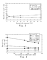
- test pieces were prepared by forming electroconductive films without the introduction of nitrogen at the time of the film formation, while the content of the addition metal and the post annealing temperature were changed respectively, and the resistivities of the electroconductive films were measured.
- Fig. 4 shows measurement results when the addition metal was Ti
- Fig. 12 shows measurement results when the addition metal was Zr.
- the resistivity was decreased by annealing after the formation of the electroconductive film, and there was a tendency that the electroconductive film into which the addition metal was incorporated decreased with the increase in the post-annealing temperature.
- the addition metal such as Zr or Ti has the property of not forming a solid solution with Cu
- the post annealing precipitated the addition metal, and thus made the resistance value approach that of Cu alone.
- the electroconductive film is heated to a predetermined film forming temperature (for example, 120°C or more) at the time of the film formation, the resistivity is decreased at a temperature lower than the post-annealing temperature.
- Glass substrates and silicon substrates were used as objects to be film-formed, and test pieces were obtained by forming electroconductive films on surfaces of the glass substrates and that of silicon layers (Si layers) of the silicon substrates.
- the film forming conditions of the electroconductive films 25 were the same as in the case where the "post-annealing temperature” was 450°C in the above “Adhesion test", except that the film thickness was changed to 350nm.
- the above "Adhesion test” and the measurement of the resistivity of the electroconductive film 25 were carried out.
- the test pieces in which the electroconductive films were formed on the surfaces of the Si layers it was confirmed whether copper diffused into the Si layers or not. In this case, whether copper diffused into the Si layers or not was confirmed by observing the surfaces of the Si layers with an electron microscope after the electroconductive films 25 were removed by etching.
- Fig. 5 shows an electron microscope photograph of a surface of a Si layer formed under the conditions that Ti was used as the addition metal, the content of Ti was 3 at% and the partial pressure of nitrogen was 3%.
- Fig. 6 shows an electron microscope photograph of a surface of a Si layer formed under the conditions that the content of Ti was zero and the partial pressure of nitrogen was 0% at the time of the film formation.
- the resistivity tends to decrease.
- the introduced amount of the nitrogen gas is set to become over 50% of the total pressure of the first vacuum atmosphere and the introduced amount of the sputtered gas is set to become less than 50% of the total pressure, the sputtering speed significantly drops and the film forming efficiency deteriorates. Therefore, the upper limit of the introduced amount of the nitrogen gas is preferably set at 50% or less of the total pressure in the first vacuum atmosphere.
- Electroconductive films 25 were formed in the case where the introduction amount of the nitrogen gas was set to become 3% of the total pressure and the contents of an addition metal (Ti, Zr) were 0.1 at%, 3 at% and 10 at%, respectively. In this case, glass substrates and silicon substrates were used as objects to be film-formed.
- the film forming conditions for the electroconductive films 25 were the same as in the above "Adhesion, resistivity, diffusion test", except that the film thickness was changed to 50nm.
- a copper film 26 was further formed in a film thickness of 300nm on a surface of the electroconductive film 25, thereby preparing a test piece in which the electroconductive film 25 and the copper film 26 were laminated.
- the copper film 26 was formed by sputtering a copper target (a pure copper target) without introducing the nitrogen gas inside the second film forming chamber 3.
- Table 5 Electrode evaluation test (Addition metal : Ti) Total film thickness : 350nm Film construction Content [at%] Partial pressure of N 2 added [%] After annealing at 450°C Resistivity [ ⁇ cm] Adhesion Diffusion into Si Cu 0 0 2.1 0/100 Diffused Cu-Ti 0.1 3.0 3.2 100/100 Not diffused 3 3.0 3.5 100/100 Not diffused 10 3.0 3.9 100/100 Not diffused Cu/Cu-Ti* 0.1 3.0 2.1 100/100 Not diffused 3 3.0 2.2 100/100 Not diffused 10 3.0 2.1 100/100 Not diffused * No nitrogen added at the time of Cu film formation Table 6 Table 6 : Electrode evaluation test (Addition metal : Zr) Total film thickness 350nm Film construction Content [at%] Partial pressure of N 2 added [%] After annealing at 450°C Resistivity [ ⁇ cm] Adhesion Diffusion into Si Cu 0 0 2.1 0/100 Diffused Cu-
- the laminated films in which the copper film 26 was laminated on the surface of the electroconductive film 25 was low in terms of resistivity at the same level as that of the copper film alone, as well as adhesion and excellent diffusion preventing property against Si as in the case of the electroconductive film 25 alone.
- the laminated film in which the copper film (containing no addition metal and prepared without introducing nitrogen gas) was formed on the electroconductive film 25 formed by the film forming method according to the present invention, is excellent particularly as an electrode that tightly adhere to the glass substrate or the silicon layer.
- test pieces formed in the above "Adhesion, resistivity, diffusion test” the glass substrates were used as the objects to be film-formed, the test pieces were prepared, in which the introduced amount of the nitrogen gas at the time of the film formation was set to become 3% of the total pressure and the contents of the addition metal (Ti, Zr) in the electroconductive films 25 were 0.1 at%, 3 at% and 10 at%, respectively.
- An ITO thin film was formed in a film thickness of 150nm on a surface of the electroconductive film 25 of each test piece.
- the ITO thin films were formed under the same conditions as in the above six kinds of the test pieces, except that test pieces formed with an Al film or a copper film instead of the above electroconductive films 25 were used.
- the copper film was formed by sputtering a pure copper target without the introduction of nitrogen gas.
- the Al films exhibited high contact resistances, and the contact resistance was so high particularly after the annealing treatment that the electroconductive film could not be used for a TFT.
- the electroconductive films 25 formed in the present application was low in the contact resistances at the same levels as those of the copper film, and increases in the contact resistances after the annealing treatment were small.
- the electroconductive film 25 formed by the present invention not only has adhesion to the Si layer and the glass substrate and excellent resistivity as described above but also excellent diffusion-preventing property for the Si layer.
- the electroconductive film exhibits a low constant resistance value to the transparent electrode such as ITO, and thus is excellent as an electrode to be tightly adhered to the ITO.
- electroconductive films 25 (alloy films) each containing 1 at% of an addition metal were prepared by sputtering under the same conditions as in the above "Adhesion test", except that each of addition metals shown in the following Table 9 was used as an auxiliary target in place of Ti and Zr.
- the kinds of the addition elements and the partial pressure of nitrogen in the vacuum chamber at the time of sputtering are shown in the following Table 9.
- Table 9 Table 9: Kinds of addition metals Addition element [each 1at%] Addition gas Partial pressure of N 2 [%] After annealing at 350°C After annealing at 450°C Resistivity Adhesion Resistivity Adhesion - - 2.0 0/100 2.0 0/100 Ag 1 2.7 100/100 2.7 100/100 B 0.1 3.1 100/100 2.9 100/100 Bi 5 4.8 100/100 4.3 100/100 C 50 4.2 100/100 3.9 100/100 Ce 3 4.4 100/100 4.3 100/100 Ce 0 8.8 54/100 8.7 53/100 Co 25 4.1 100/100 4.1 100/100 Cr 0.5 3.9 100/100 3.8 100/100 Fe 3 4.6 100/100 4.5 100/100 Hf 1 3.3 100/100 3.2 100/100 Hf 0 9.9 57/100 9.8 52/100 Nb 5 4.2 100/100 4.0 100/100 Nb 0 7.5 63/100 7.3 65/100 Os 0.1 4.7 100/100
- test pieces were prepared, and, with respect to the alloy film of each of the test pieces, measurement of the resistivity and the adhesion test were performed. Results thereof were shown in the above Table 9.
- the alloy film using each of the addition metals enhanced the adhesion when the nitrogen gas was contained as compared to cases where no nitrogen gas was contained at the time of sputtering (the partial pressure of the nitrogen gas 0%).
- TFT thin film transistor
- a reference numeral 41 indicates a transparent substrate having an insulating layer (for example, a SiO 2 layer) 42 on a surface, and a silicone layer 61 composed mainly of Si and added with a dopant is arranged at a predetermined area on a surface of the insulating layer 42.
- an insulating layer for example, a SiO 2 layer
- a source area 62 and a drain area 64 are formed on the silicon layer 61, and a channel area 63 is formed between the source area 62 and the drain area 64.
- a gate oxide film 66 is formed on the surface of the silicon layer 61 over the source area 62, the channel area 63 and the drain area 64, and a gate electrode 67 is disposed on the surface of the gate oxide film 66.
- the face of the insulating layer 42 on which the gate electrode 67 is arranged is covered with a first interlayer insulating film 43.
- a first through-hole 69a and a second through-hole 69b are formed in such a manner that the portion of the source area 62 protruding from the gate oxide film 66 is exposed at a bottom face of the first through-hole 69a and the portion of the drain area 64 protruding from the gate oxide film 66 is exposed at a bottom face of the second through-hole 69b.
- the first interlayer insulating film 43 is formed with a first through-hole 69a and a second through-hole 69b in such a manner that the portion of the source area 62 protruding from the gate oxide film 66 is exposed at a bottom face of the first through-hole 69a, whereas the portion of the drain area 64 protruding from the gate oxide film 66 is exposed at a bottom face of the second through-hole 69b.
- the transparent substrate 41 in this state is carried in the film forming apparatus 1 shown in Fig. 1 as an object to be film-formed, a first electroconductive film is formed, by the step shown in Fig. 2(b) , on the face on which the first interlayer insulating film 43 is formed; and further, a copper film is formed on the surface of the first electroconductive film by the step shown in Fig. 2(c) .
- Fig. 7(b) shows a state in which the first electroconductive film 52 and the copper film 53 are formed.
- the first electroconductive film 52 is tightly adhered to the surface of the first interlayer insulating film 43 and the inner wall faces and the bottom faces of the first and second through-holes 69a and 69b. Therefore, the first electroconductive film 52 is tightly adhered to the surface of the source area 62 and that of the drain area 64 at the bottom faces of the first and second through-holes 69a, 69b, respectively.
- the interiors of the first and second through-holes 69a, 69b are filled with the first electroconductive film 52 and the copper film 53.
- the transparent substrate 41 in this state is returned from the second film forming chamber 3 to the first film forming chamber 2; and a second electroconductive film 54 is formed on the surface of the copper film 53 by the same method as that of forming the first electroconductive film 52 on the surface of the first interlayer insulating film 43 ( Fig. 7(c) ).
- a reference numeral 50 indicates an electroconductive body consisting of the first and second electroconductive films 52, 54 and the copper film 53.
- the resistance of the entire electroconductive body 50 can be reduced.
- this electroconductive body 50 is patterned to separate a portion filled in the first through-hole 69a of the electroconductive body 50 from a portion filled in the second through-hole 69b of the electroconductive body 50.
- a reference numeral 51 indicates a source electrode constituted by the portion filled in the first through-hole 69a of the electroconductive body 50 and a portion remaining therearound
- a reference numeral 55 in the same figure indicates a drain electrode constituted by the portion filled in the second through-hole 69b of the electroconductive body 50 and a portion remaining therearound.
- the source electrode 51 and the drain electrode 55 are separated from each other by the above-described patterning.
- the first electroconductive film 52 tightly adheres to the source area 62 and the drain area 64 at the bottom faces of the first and second through-holes 69a, 69b, the first electroconductive film 52 of the source electrode 51 is connected to the source area 62; and the first electroconductive film 52 of the drain electrode 55 is connected to the drain area 64.
- the copper film 53 and the second electroconductive film 54 are electrically connected to the first electroconductive film 52
- the copper film 53 and the second electroconductive film 54 of the source electrode 51 are electrically connected to the source area 62 via the first electroconductive film 52.
- the copper film 53 and the second electroconductive film 54 of the drain electrode 55 are electrically connected to the drain area 64 via the first electroconductive film 52. Therefore, the entire source electrode 51 is electrically connected to the source area 62, and the entire drain electrode 55 is electrically connected to the drain area 64.
- a second interlayer insulating film 44 is formed on that face of the transparent substrate 41 on a side of which the source electrode 51 and the drain electrode 55 are formed.
- Shield films 76 are disposed at the predetermined positions of the surface of the second interlayer insulating film 44.
- a third interlayer insulating layer 46 is formed on that face of the second interlayer insulating film 44 on a side of which the shielding film 76 is arranged ( Fig. 8(a) ).
- a third through-hole 72 which communicates with the second and third interlayer insulating films 44, 46, is formed at a position immediately above the drain electrode 55; and the second electroconductive film 54 of the drain electrode 55 is exposed to the bottom face of the third through-hole 72.
- an ITO transparent electroconductive film is formed, by sputtering or the like, on that face on a side of which the third through-hole 72 is formed; and the transparent electroconductive film is patterned, so that a transparent electrode 71 is constituted by a transparent electroconductive film filled in the third through-hole 72 and the transparent electroconductive film remaining above the third through-hole 72 and therearound ( Fig. 8(b) ).
- reference numeral 40 indicates a TFT panel (thin film transistor-provided panel) in a state that the transparent electrode 71 is formed.
- the transparent electrode 71 is electrically connected to the second electroconductive film 54 of the drain electrode 55.
- the copper film 53 of the drain electrode 55 and the first electroconductive film 52 are electrically connected to the transparent electrode 71 via the second electroconductive film 54; the entire drain electrode 55 is electrically connected to the transparent electrode 71; and the transparent electrode 71 and the drain area 64 are electrically connected via the drain electrode 55.
- the source electrode 51 is connected to a source wiring (not shown).
- a voltage is applied to the gate electrode 67 in a state that a voltage is applied between the source electrode 51 and the drain electrode 55, electric current flows through the channel area 63 between the source area 62 and the drain area 64.
- the transparent electrode 71 is connected to the source electrode 51 via the drain electrode 55, the drain area 64, the channel area 63 and the source area 62.
- the source electrode 51 and the drain electrode 55 are hardly peeled from the silicon layer 61.
- the first and second electroconductive films 52, 54 have high diffusion-preventing property, the component metal (Cu) of the copper film 53 does not diffuse into the silicon layer 61.
- first and second electroconductive films 52, 54 formed by the present invention have low resistivities as well as a low contact resistance against the transparent electroconductive film, the source electrode 51 and the drain electrode 55 of the TFT 60 exhibit excellent conductivity.
- the electroconductive film formed by the present invention is suitable as a barrier film for the electrode tightly adhering to the silicon layer 61 and the transparent electrode 71.
- wirings such as a gate wiring film, a source wiring film or the like, and other electric parts are arranged at a position away from the TFT 60 on the surface of the transparent substrate 41 of the TFT panel 40.
- the gate wiring film 74 is shown.
- a reference numeral 80 indicates a second embodiment of a TFT panel produced by the present invention.
- This TFT panel 80 comprises a transparent substrate 82 and a TFT 90 arranged on a surface of the transparent substrate 82.
- a gate electrode 83 of this TFT 90 is arranged on a surface of the transparent substrate 82; and an insulating film 84, which covers the surface and the side face of the gate electrode 83, is formed on that face of the transparent substrate 82 on which the gate electrode 83 is arranged.
- a silicon layer 86 is arranged on the gate electrode 83 of the surface of the insulating film 84; and a transparent electrode 85 made of a transparent electroconductive film is arranged at a position apart from the silicon layer 86 on the surface of the insulating film 84.
- a source area 87, a channel area 88 and a drain area 89 are formed in the silicon layer 86.
- a bottom face of a source electrode 91 is tightly adhered to a surface of the source area 87; and a bottom face of a drain electrode 92 is tightly adhered to a surface of the drain area 89.
- a part of the drain electrode 92 is extended up to the transparent electrode 85, and its bottom face is tightly adhered to a surface of the transparent electrode 85. Therefore, the bottom face of the drain electrode 92 is tightly adhered to both the drain area 89 and the transparent electrode 85.
- the source electrode 91 and the drain electrode 92 comprise an electroconductive film 93 formed by the forming method of the present invention, and a copper film 94 arranged on the surface of the electroconductive film 93.
- the source electrode 91 and the drain electrode 92 are formed by, for example, using the transparent substrate 82 with the transparent electrode 85 and the silicon layer 86 exposed on the surface thereof as an object to be film-formed, forming an electroconductive film over the entire surface of the object at which the transparent electrode 85 and the silicon layer 86 are exposed, forming a copper film on the surface of the electroconductive film, and thereafter patterning the electroconductive film and the copper film together.
- the electroconductive film 93 is located in the bottom faces of the drain electrode 92 and the source electrode 91, respectively. Since the bottom face of the drain electrode 92 is tightly adhered to both the drain area 89 and the transparent electrode 85 as mentioned above, the electroconductive film 93 of the drain electrode 92 is electrically connected to both the transparent electrode 85 and the drain area 89.
- the copper film 94 of the drain electrode 92 is electrically connected to both the transparent electrode 85 and the drain area 89 via the electroconductive film 93, and the entire drain electrode 92 is electrically connected to both the drain area 89 and the transparent electrode 85.
- the electroconductive film 93 of the source electrode 91 is electrically connected to the source area 87; the copper film 94 of the source electrode 91 is electrically connected to the source area 87 via the electroconductive film 93; and the entire source electrode 91 is electrically connected to the source area 87.
- the electroconductive film 93 formed by the present invention has a low contact resistance to ITO as described above, conductivity is excellent between the drain electrode 92 and the transparent electrode 85.
- the source electrode 91 is connected to a source wiring (not shown).
- a voltage is applied to the gate electrode 83 in a state that a voltage is applied between the source electrode 91 and the drain electrode 92, electric current flows between the source area 87 and the drain area 89 via the channel area 88.
- the transparent electrode 85 is connected to the source electrode 91 via the source area 87, the channel area 88, the drain area 89 and the drain electrode 92.
- a reference numeral 140 indicates a TFT panel of a third embodiment of the present invention.
- This TFT panel 140 has the same construction as the TFT panel 40 shown in the above Fig. 8(b) , except that a source electrode 151 and a drain electrode 155 are constituted by only an electroconductive film formed by the present invention.
- the resistance increases due to the lamination of no copper film, the film having a lower resistance can be obtained as compared to Al or the like.
- the TFT panels of the present invention are used for liquid crystal displays, organic EL display devices, etc.
- ITO is used as the component material of the transparent electrodes 71, 85 in the above description, the present invention is not limited thereto.
- the target portion 10 used for forming the electroconductive film is not particularly limited.
- the target portion 10 may be constituted by a single plate of a target (alloy target) composed mainly of copper and containing one or more kinds of addition metals.
- the shape of the alloy target is not particularly limited, and takes a planar shape (such as, rectangular, square or circular shape).
- the alloy target is arranged inside the film forming chamber (first film forming chamber 2) in place of the target portion 10 in Fig. 1 .
- An electroconductive film is formed by sputtering the alloy target in such a state that an object to be film-formed is arranged, while a face on which the electroconductive film is to be formed is faced toward the surface of the alloy target.
- the magnetic field forming device 14 is arranged on a rear face side of the alloy target.
- the target portion 10 is constituted by the alloy target and in a case where the target portion 10 is constituted by the main target 11 and the auxiliary target 12, copper atoms and addition metal atoms are ejected from the target portion 10 by sputtering, so that the electroconductive films (the first and second electroconductive films) containing both the copper atoms and the addition metal atoms grow on the surface of the object to be film-formed.
- the electroconductive film is formed by sputtering the target portion 10 while the nitrogen gas and the sputtering gas are introduced into the interior of the first film forming chamber 2.
- the first film forming chamber 2 is evacuated to a vacuum and the partial pressure of the nitrogen gas inside the interior of the first film forming chamber 2 is reduced from that at the time of forming the electroconductive film. Consequently, the copper film may be formed by sputtering the same target portion 10 used for the formation of the electroconductive film.
- the copper film contains the same addition metal as in a case of the first and second electroconductive films
- the resistivity of the copper film is smaller than those of the first and second electroconductive films because of the lower partial pressure of the nitrogen gas at the time of the film formation.
- the first and second electroconductive films 52, 54 may be formed by using the same target portion 10, or they may be formed by using different target portions 10, so that the kinds and the contents of the addition metals may be changed. Further, the partial pressures of nitrogen at the time of the formation of the first and second electroconductive films 52, 54 may be the same or changed.
- the annealing method is not particularly limited, the annealing is preferably performed in a vacuum atmosphere.
- the object on which the electroconductive film has been formed is transferred into another film forming chamber or a heating device, it is preferable that the object to be film-formed is transferred in a vacuum atmosphere without being exposed to the atmosphere.
- the sputtering gas is not limited to Ar; and Ne, Xe or the like can be used besides Ar.
- the electroconductive films formed by the present invention can be used for TFTs and electrodes and barrier films of TFT panels as well as barrier films and electrodes (wiring films) of other electric parts (such as, semiconductor elements or wiring boards).
- the film thickness of the electroconductive film is not particularly limited. However, if it is too thick, the resistivity of the entire electrode becomes higher. Therefore, the film thickness of the electroconductive film is preferably 1/3 or less of that of the entire electrode. Further, when the adhesion and the diffusion preventing property for the silicon layer and the glass substrate are taken into consideration, the film thickness of the electroconductive film is preferably 10nm or more.
- the nitriding gas is not particularly limited, as long as it is a gas containing a nitrogen atom in a chemical structure.
- NH 3 , hydrazine, an amine-based alkyl compound, an azide compound, etc. can be used besides nitrogen (N 2 ).
- These nitriding gases may be used alone or two or more kinds of these nitriding gases may be used in a mixed state.
- the transparent substrate is not limited to the glass substrate, and, for example, a quartz substrate and a plastic substrate can be used.
- the kind of the silicon layer and the producing method which is employed in the present invention are not particularly limited.
- the kinds of silicon layer which are used as silicon layers in TFT including a silicon layer (an amorphous silicon layer, a polysilicon layer) deposited by, for example, sputtering, vapor deposition or the like can be widely used.
- addition metal to be used in the present invention Ti, Zr, Hf, V, Nb, Ta, Cr, Mo, W, Mn, Fe, Ru, Os, Co, Ni, Bi, Ag, Zn, Sn, B, C, Al, Si, La, Ce, Pr and Nd are preferable. Only one kind thereof may be used to form an electroconductive film containing one kind of the addition metal, or two or more kinds of the addition metal may be used to form an electroconductive film containing two or more kinds of the addition metals.
- IV group elements such as Ti and Zr are particularly suitable for the present application.
- a so-called bottom gate type TFT can be produced by forming a gate electrode on a surface of a glass substrate.
- a substrate for example, a glass substrate is transferred as an object to be film-formed into the interior of the vacuum chamber 2 of the film forming apparatus 1 in Fig. 1 .
- An electroconductive body is formed on the surface of the substrate by laminating a first electroconductive film, a copper film and a second electroconductive film in the described order in the same steps as those explained in the above Figs. 7(a) to (c) .
- Fig. 13(a) shows a state in which the electroconductive body 213 is formed on the surface of the substrate 211.
- the electroconductive body 213 is patterned in a photographing step and an etching step, and a gate electrode 215 and a storage capacity electrode 212 are formed by the patterned electroconductive body 213, as shown in Fig. 13(b) .
- Fig. 15 is an enlarged sectional view of a portion in which the gate electrode 215 (or the storage capacity electrode 212) is arranged.
- the gate electrode 215 and the storage capacity electrode 212 have the first and second electroconductive film 251, 252 and the copper film 253, as mentioned above.
- the first electroconductive film 251 is tightly adhered to the substrate 211; the second electroconductive film 252 is tightly adhered to the gate insulating film 214; and the copper film 253 is positioned between the first and second electroconductive films 251, 252.
- first and second electroconductive films 251, 252 contain nitrogen and the addition metal, they have high adhesion to the substrate 211 and the gate insulating film 214.
- the copper film 253 having a low electric resistance is arranged between the first and second electroconductive films 251 and 252, the entire electric resistance of the gate electrode 215 and the storage capacity electrode 212 is low.
- a channel semiconductor layer (channel area) 216 made of, for example, amorphous silicon is formed on the surface of the gate insulating film 214 by the CVD method or the like ( Fig. 13(d) ).
- an ohmic layer 217 composed mainly of silicon and containing an impurity is formed on the surface of the channel semiconductor layer 216 by the CVD method or the like ( Fig. 13(e) ).
- the substrate 211 on which the ohmic layer 217 is formed is transferred into the vacuum chamber 2 of the film forming apparatus 1 in Fig. 1 ; and an electroconductive body 223 is formed by laminating a first electroconductive film 251, a copper layer 253 and a second electroconductive layer 252 in the described order by the same steps as in the film formation of the above-mentioned electroconductive body 213 ( Fig. 14(a) ).
- the electroconductive layer 223, the ohmic layer 217 and the channel semiconductor layer 216 are patterned by a photographing step and an etching step.
- reference numerals 225 and 226 indicate a source semiconductor layer (source area) and a drain semiconductor layer (drain area), respectively.
- the source semiconductor layer 225 and the drain semiconductor layer 226 are constituted by the portions retained on the opposite sides of the gate electrode 215 of the ohmic layer 217.
- reference numerals 221, 222 indicate a source electrode and a drain electrode, respectively.
- the source electrode 221 and the drain electrode 222 are constituted by portions of the electroconductive body 223 retained on the opposite sides of the gate electrode 215.
- an interlayer insulating film 224 composed of a silicon nitride film, a silicon oxide film or a silicon nitride oxide is formed on the surfaces of the source electrode 221 and the drain electrode 222 by the CVD method or the like ( Fig. 14(c) ).
- a reference numeral 220 in Fig. 14(c) indicates a thin film transistor (TFT) in which the interlayer insulating film 224 is formed.
- a reference numeral 210 indicates a thin film transistor-provided panel.
- the source electrode 221 and the drain electrode 222 have the first and second electroconductive films 251, 252 and the copper film 253 as in a case with the gate electrode 215 and the storage capacity electrode 212.
- the first electroconductive film 251 is tightly adhered to the ohmic layer 217; the second electroconductive film 252 is tightly adhered to the interlayer insulating film 224; and the copper film 253 is positioned between the first and second electroconductive films 251 and 252.
- the ohmic layer 217 has a main component of silicon. Since the first and second electroconductive films 251, 252 contain nitrogen and the addition metal, they have high adhesion to silicon and the insulating film. Therefore, the source electrode 221 and the drain electrode 222 are hardly peeled from the ohmic layer 217 and the interlayer insulating film 224. In addition, copper does not diffuse from the first and second electroconductive films 251, 252 into the ohmic layer 217.
- this thin film transistor 220 by means of an opening 218 positioned immediately above the center of the gate electrode 215, the source semiconductor layer 225 and the drain semiconductor layer 226 are separated from each other and the source electrode 221 and the drain electrode 222 are separated from each other. That opening 218 is filled with the interlayer insulating film 224.
- the channel semiconductor layer 216 is the same electroconductive type as that of the source and drain semiconductor layers 225, 226, but its impurity concentration is lower.
- the channel semiconductor layer 216 may be an electroconductive type opposite to that of the source and drain semiconductor layers 225, 226.
- Fig. 14(d) shows a state such that after windows are opened at a portion above the drain electrode 222 or the source electrode 221 (here, the drain electrode 222) of the interlayer insulating film 224 and at a portion above the storage capacity electrode 212, a patterned transparent electroconductive film is arranged on the interlayer insulating film 224.
- a reference numeral 227 indicates a pixel electrode made of that portion of the transparent electroconductive film which is positioned on a side of the thin film transistor 220.
- a reference numeral 228 indicates a connecting portion which is composed of that portion of the transparent electroconductive film which is positioned on the thin film transistor 220 and has contact with the drain electrode 222.
- the pixel electrode 227 is electrically connected to the drain electrode 222 via the connecting portion 228, so that when the source semiconductor layer 225 is electrically connected to the drain semiconductor layer 226, electric current flows into the pixel electrode 227.
- a reference numeral 204 indicates a liquid crystal display device in which liquid crystals 241 are arranged between a panel 240 and a substrate 211 on which the TFT 220 is formed.
- the panel 240 has a glass substrate 242 and an opposed electrode 245 arranged on a surface of the glass substrate 242.
- the opposed electrode 245 and the pixel electrode 227 face each other across the liquid crystal 241.
- the light transmission rate of the liquid crystals 241 can be changed by controlling the voltage to be applied between the pixel electrode 227 and the opposed electrode 245.
- the liquid crystal display device 204 may be produced by using the substrate 211 on which any of the TFTs in the first to third embodiments is formed, instead of the TFT 220 in the fourth embodiment.
- the electroconductive body 223 constituting the electrode is not limited to the three-layer structure, and at least one of the source electrode 221, the drain electrode 222, the gate electrode 215 and the storage capacity electrode 212 may be constituted by the first electroconductive film 251 alone.
- the electroconductive film formed by the present invention has the main component of copper and contains the addition metal, it has high adhesion to the glass substrate, the silicon layer, the transparent electroconductive film, etc. Therefore, the object used to form an electroconductive film thereon may not be particularly limited.
- an object to be film-formed from which a transparent electroconductive film is exposed is used; and an electroconductive film is formed on the transparent electroconductive film.
- an object to be film-formed from which a glass substrate and a silicon layer are exposed is used; and an electroconductive film may be formed on a surface of the glass substrate and a surface of the silicon layer.
- an object to be film-formed from which a glass substrate, a transparent electroconductive film and a silicon layer are exposed, respectively, is used; and an electroconductive film may be formed on a surface of the glass substrate, a surface of the transparent electroconductive film and a surface of the silicon layer, respectively.
Abstract


Description
- The present invention generally relates to metallic wiring films for electronic parts and a sputtering method as a method for forming such films.
- Heretofore, low-resistance materials (such as, Al and Cu, Mo, or Cr) have been used in metallic wiring films for electronic parts. For instance, in the case of the TFT (Thin film transistor) liquid crystal displays, a demand for the reduction in the resistance of the wiring electrodes has been increasing with the enlargement of the panels, and the necessity for using Al and Cu as the low-resistance wirings has been growing.
- In the case of the Al wiring used in a TFT, there have been problems in that, for example, a hillock occurs in a post process, diffusion occurs into an underling Si layer when the Al wirings are used as source and drain electrodes, and a contact resistance between the wiring and a transparent electrode made of ITO (indium-tin oxide) degrades. In order to avoid such problems, a barrier layer on opposing sides of which alloy layers composed mainly of Mo or Cr or an alloy thereof are laminated becomes necessary.
- On the other hand, with respect to the Cu wiring, Cu is a material having a lower resistance than that of Al. Although degradation in the contact resistance between Al and the ITO transparent electrode poses a problem, Cu exhibits an excellent contact resistance because of its resistance to oxidation.
- Consequently, a need for the use of Cu as a low-resistance wiring film has been increasing. However, as compared to other wiring materials, there have been problems in that Cu has poor adhesion to underlying materials (such as, glass and Si), and Cu diffuses into a Si layer when it is used as source and drain electrodes. A barrier layer is required at an interface between the Cu wiring and other layer so as to enhance the adhesion and prevent the diffusion.
- Regarding an underlying Cu seed layer made of a Cu plating, which is used in a semiconductor, a barrier layer is required to prevent the diffusion of TiN, TaN or the like from the same diffusion problem as described above.
- As to related patents on metallic wiring films composed mainly of Cu for electronic parts, a technique characterized by adding an element such as Mo into Cu (
JP-A 2005-158887 JP-A 10-12151 - Patent Document:
JP-A 2005-158887 - Patent Document:
JP-A 10-12151 - The present invention is to solve the problems of the prior art as described above, and is aimed at providing a method for producing a Cu-based wiring film and a film of a Cu-based barrier layer, which are excellent in terms of reduced resistance, a contact resistance between an ITO transparent electrode, adhesion to glass and Si, prevention of diffusion into an Si layer when the Cu-based wiring film is used as source and drain electrodes, a hillock resistance, and film characteristics required for these devices.
- In order to solve the above problems, the present invention is directed to an electroconductive film-forming method for forming an electroconductive film composed mainly of copper and contains an addition metal on a surface of an object to be film-formed in a vacuum atmosphere by a sputtering method, the forming-method comprising sputtering a target composed mainly of copper in the vacuum atmosphere, while feeding a nitriding gas having a nitrogen atom in a chemical structure thereof into the vacuum atmosphere, ejecting copper atoms and atoms of any one kind of an addition metal selected from the group consisting of Ti, Zr, Hf, V, Nb, Ta, Cr, Mo, W, Mn, Fe, Ru, Os, Co, Ni, Bi, Ag, Zn, Sn, B, C, Al, Si, La, Ce, Pr and Nd from the target, and forming the electroconductive film.
- The present invention is directed to the electroconductive film-forming method, wherein the object to be film-formed is used, in which any one or more of a silicon layer, a glass substrate and a transparent electroconductive film are exposed from a surface of the object.
- The present invention is directed to the electroconductive film-forming method, wherein Ti is selected as the addition metal, a nitrogen gas is used as the nitriding gas, the nitrogen gas is introduced in such a manner that a partial pressure of the nitrogen gas to the total pressure of the vacuum atmosphere may be 0.1% or more and 50% or less, and Ti is contained in the electroconductive film by 0.1 atomic% or more.
- The present invention is directed to a thin film transistor comprising a gate electrode, a drain area composed mainly of silicon and a source area composed mainly of silicon, wherein the drain area and the source area are electrically conducted when a voltage is applied to the gate electrode and wherein a first electroconductive film mainly composed of copper is formed on either one or both of a surface of the drain area and that of the source area, the first electroconductive film is formed by arranging in a vacuum atmosphere an object to be film-formed in which either one or both of the drain area and the source area are exposed, sputtering a target composed mainly of copper in the vacuum atmosphere, while feeding a nitriding gas having a nitrogen atom in a chemical structure into the vacuum atmosphere, and ejecting copper atoms and atoms of any one kind of an addition metal selected from the group consisting of Ti, Zr, Hf, V, Nb, Ta, Cr, Mo, W, Mn, Fe, Ru, Os, Co, Ni, Bi, Ag, Zn, Sn, B, C, Al, Si, La, Ce, Pr and Nd from the target.
- The present invention is directed to the thin film transistor, wherein the first electroconductive film contains Ti as the addition metal by 0.1 atomic% or more and the first electroconductive film is formed by feeding the nitriding gas composed of a nitrogen gas in such a manner that a partial pressure of the nitriding gas to the total pressure of the vacuum atmosphere may be 0.1% or more to 50% or less.
- The present invention is directed to a thin film transistor-provided panel comprising a substrate, and a thin film transistor and a transparent electroconductive film disposed on a surface of the substrate, respectively, wherein the thin film transistor comprises a gate electrode, a drain area composed mainly of silicon and a source area composed mainly of silicon. When a voltage is applied to the gate electrode, the drain area and the source area are electrically conducted and the transparent electroconductive film is connected to the source area. A first electroconductive film composed mainly of copper is formed on either one or both of a surface of the drain area and that of the source area; and the first electroconductive film is formed by arranging in a vacuum atmosphere an object to be film-formed in which either one or both of the drain area and the source area are exposed, sputtering a target composed mainly of copper in the vacuum atmosphere while feeding a nitriding gas having a nitrogen atom in a chemical structure into the vacuum atmosphere, and ejecting copper atoms and atoms of any one kind of an addition metal selected from the group consisting of Ti, Zr, Hf, V, Nb, Ta, Cr, Mo, W, Mn, Fe, Ru, Os, Co, Ni, Bi, Ag, Zn, Sn, B, C, Al, Si, La, Ce, Pr and Nd from the target.
- The present invention is directed to the thin film transistor-provided panel, wherein the first electroconductive film is tightly adhered to both of the drain area and the transparent electroconductive film.
- The present invention is directed to the thin film transistor-provided panel, wherein Ti is selected as the addition metal, a nitrogen gas is used as the nitriding gas, the nitrogen gas is introduced in such a manner that a partial pressure of the nitrogen gas to the total pressure of the vacuum atmosphere may be 0.1% or more and 50% or less, and Ti is contained in the first electroconductive film by 0.1 atomic% or more.
- The present invention is directed to the thin film transistor-provided panel, wherein a second electroconductive film electrically connected to the first electroconductive film is disposed on a surface of the first electroconductive film; and the transparent electroconductive film is arranged on a surface of the second electroconductive film. The second electroconductive film is formed by arranging, in a vacuum atmosphere, the substrate in which the thin film transistor and the first electroconductive film have been formed, sputtering a target composed mainly of copper in the vacuum atmosphere while feeding a nitriding gas having a nitrogen atom in a chemical structure into the vacuum atmosphere, and ejecting copper atoms and atoms of any one kind of an addition metal selected from the group consisting of Ti, Zr, Hf, V, Nb, Ta, Cr, Mo, W, Mn, Fe, Ru, Os, Co, Ni, Bi, Ag, Zn, Sn, B, C, Al, Si, La, Ce, Pr and Nd from the target.
- The present invention is directed to the thin film transistor-attached panel, wherein a copper film composed mainly of copper is arranged on a surface of the first electroconductive film, the object to be film-formed in which the copper film is exposed is used, and the second electroconductive film is formed on a surface of the copper film.
- The present invention is directed to the thin film transistor-provided panel, wherein Ti is selected as the addition metal, a nitrogen gas is used as the nitriding gas, the nitrogen gas is introduced in such a manner that a partial pressure of the nitrogen gas to the total pressure of the vacuum atmosphere may be 0.1% or more and 50% or less, and Ti is contained in the second electroconductive film by 0.1 atomic% or more.
- The present invention is directed to a method for producing a thin film transistor comprising an electroconductive film which is in contact with one or more of a silicon layer composed mainly of silicon, a glass substrate and a transparent electroconductive film, wherein the electroconductive film is composed mainly of copper, the producing method comprising sputtering a target composed mainly of copper in a vacuum atmosphere, while feeding a nitriding gas having a nitrogen atom in a chemical structure into the vacuum atmosphere, in such a state where an object to be film-formed in which any one or more of the silicon layer, the glass substrate and the transparent electroconductive film are exposed is arranged in the vacuum atmosphere, ejecting copper atoms and atoms of any one kind of an addition metal selected from the group consisting of Ti, Zr, Hf, V, Nb, Ta, Cr, Mo, W, Mn, Fe, Ru, Os, Co, Ni, Bi, Ag, Zn, Sn, B, C, Al, Si, La, Ce, Pr and Nd from the target, and forming the electroconductive film.
- The present invention is directed to the thin film transistor-producing method, wherein the nitriding gas is introduced in such a manner that a partial pressure of the nitriding gas to the total pressure of the vacuum atmosphere may be 0.1% or more and 50% or less, and the sputtering is performed.
- The present invention is directed to a method for producing a thin film transistor comprising a silicon layer composed mainly of silicon, a first electroconductive film in contact with the silicon layer, a copper film composed mainly of copper and formed on a surface of the first electroconductive film, and a second electroconductive film formed on a surface of the copper film, wherein a transparent electroconductive film is in contact with the second electroconductive film and the first and second electroconductive films are composed mainly of copper, the thin film transistor-producing method comprising sputtering a target composed mainly of copper in a vacuum atmosphere, while feeding a nitriding gas having a nitrogen atom in a chemical structure into the vacuum atmosphere, ejecting copper atoms and atoms of any one kind of an addition metal selected from the group consisting of Ti, Zr, Hf, V, Nb, Ta, Cr, Mo, W, Mn, Fe, Ru, Os, Co, Ni, Bi, Ag, Zn, Sn, B, C, Al, Si, La, Ce, Pr and Nd from the target, and forming either one or both of the first and second electroconductive films.
- The present invention is directed to the thin film transistor-producing method, wherein the nitriding gas is introduced in such a manner that a partial pressure of the nitriding gas to the total pressure of the vacuum atmosphere may be 0.1% or more and 50% or less, and the sputtering is performed.
- It is noted that the first and second electroconductive films may be integrated so long as they are electrically connected to each other; alternatively, another electroconductive film (such as a pure copper film) may be disposed closely between the first and second electroconductive films.
- The present invention is constructed as described above, and the target (a target portion) is constituted by a main target composed mainly of copper and an auxiliary target composed mainly of the addition metal; alternatively, the target (a target portion) is constituted by an alloy target composed mainly of copper and containing the addition metal. In either case, when the target portion is sputtered, copper atoms and atoms of the addition metal are ejected.
- The main component in the present invention means that the atoms as the main component are contained in 50 at% (atomic %) or more. That is, as to the target composed mainly of copper, it contains not less than 50 at% of the copper atoms.
- Meanwhile, the pure copper in the present invention contains not less than 99.9 at% of copper. Although the first and second electroconductive films are composed mainly of copper, they contain the addition metal, and the content of copper is lesser therein (less than 99.9 at%) than the pure copper.
- Any one or both of the content of the nitrogen atoms and the content of the addition metal are smaller in the copper film than in the first and second electroconductive films, and the resistivity of the copper film is smaller than that of any one of the first and second electroconductive films.
- In order to reduce the content of the addition metal, the film is formed by sputtering a target having a smaller content of the addition metal (for example, a target of pure copper) in the vacuum atmosphere. When the pure copper target is used, the content of the addition metal in the pure copper target is less than 0.01 at%.
- In order to reduce the content of the nitrogen atoms, the copper film is formed by sputtering the copper target in the vacuum atmosphere having a lower partial pressure of the nitriding gas than in the case of the vacuum atmosphere (first vacuum atmosphere) in which the first and second electroconductive films are formed.
- According to the present invention, the electroconductive film having a low resistance and high adhesion to the object to be film-formed can be obtained. Further, when the electroconductive film is formed so as to be tightly adhered to the silicon layer, copper does not diffuse into that silicon layer. When the electroconductive film is formed so as to be tightly adhered to the transparent electroconductive film, the contact resistance to the transparent electroconductive film is also low. Therefore, the electroconductive film is suitable particularly as a film to be tightly adhered to the silicon layer or the transparent electroconductive film, and is more particularly suitable as a source electrode and a drain electrode of a TFT and a barrier film for these electrodes.
-
-
Fig. 1 is a sectional view for illustrating one embodiment of a film-forming apparatus to be used in the present invention. -
Figs. 2(a) to (c) are sectional views for illustrating steps of forming an electroconductive film and a copper film. -
Fig. 3 is a graph showing the relationship between the partial pressure of the nitrogen gas and the resistivity (Ti). -
Fig. 4 is a graph showing the relationship between the post-annealing temperature and the resistivity (Ti). -
Fig. 5 is an electron microscope photograph showing the diffusiveness of a silicon layer in an electroconductive film. -
Fig. 6 is an electron microscope photograph showing the dispersibility of a silicon layer in a copper film. -
Figs. 7(a) to (d) are sectional views for illustrating a former half portion of steps of producing a TFT panel as a first embodiment. -
Figs. 8(a) and (b) are sectional views for illustrating a latter half portion of the steps of producing the TFT panel as the first embodiment. -
Fig. 9 is a sectional view for illustrating a second embodiment of the TFT panel according to the present invention. -
Fig. 10 is a sectional view for illustrating a third embodiment of the TFT panel according to the present invention. -
Fig. 11 is a graph showing the relationship between the partial pressure of the nitrogen gas and the resistivity (Zr). -
Fig. 12 is a graph showing the relationship between the post-annealing temperature and the resistivity (Zr). -
Figs. 13(a) to (e) are sectional views for illustrating a former half portion of steps of producing a TFT panel according to a fourth embodiment. -
Figs. 14(a) to (d) are sectional views for illustrating a latter half portion of the steps of producing the TFT panel according to the fourth embodiment. -
Fig. 15 is an enlarged sectional view for illustrating a gate electrode and a storage capacity electrode. -
Fig. 16 is a sectional view for illustrating one embodiment of a liquid crystal display device. - 1 --- film-forming apparatus, 2 --- first film-forming chamber (vacuum chamber), 10 --- target portion, 11 --- main target, 12 --- auxiliary target, 22, 41, 82 --- substrate, 23, 61, 86 --- silicon layer, 25, 52, 54, 93 --- electroconductive film (first and second electroconductive films), 26 --- copper film, 40, 80, 140 --- TFT panel, 60, 90, 220 --- TFT, 62, 87, 225 --- source area, 64, 89, 226 --- drain area, 71, 85transparent electrode (transparent electroconductive film)
- The steps of forming an electroconductive film according to the present invention will be explained in detail.
- In
Fig. 1 , areference numeral 1 indicates one example of a film forming apparatus to be used in the present invention. Thefilm forming apparatus 1 has a firstfilm forming chamber 2 with a vacuum chamber. Avacuum evacuation system 9, a sputteringgas feeding system 6 and a nitrogengas feeding system 8 are connected to the firstfilm forming chamber 2. - When an electroconductive film is to be formed by using this
film forming apparatus 1, the inside of the firstfilm forming chamber 2 is first evacuated to a vacuum by thevacuum evacuating system 9, a sputtering gas and a nitriding gas (a nitrogen gas and N2 in this case) are fed into the firstfilm forming chamber 2 from the sputteringgas feeding system 6 and the nitrogengas feeding system 8, respectively, while the vacuum evacuation is being continued, and thereby a first vacuum atmosphere containing the nitrogen gas is formed at a predetermined pressure. - In
Fig. 2(a) , areference numeral 21 indicates an object to be film-formed in which a silicon layer 23 (an amorphous silicon layer here) is formed on a surface of asubstrate 22. Theobject 21 to be film-formed is carried into the firstfilm forming chamber 2, while the first vacuum atmosphere is being kept by continuing the introduction of the sputtering gas and the nitrogen gas, and by continuing the vacuum evacuation. - A
substrate holder 7 and atarget portion 10 are arranged so as to face each other inside the firstfilm forming chamber 2, and theobject 21 to be film-formed is held by thesubstrate holder 7 in such a manner that a face on which thesilicon layer 23 has been formed is faced toward thetarget portion 10. Aheater 4 is arranged on a back face side of thesubstrate holder 7, and theobject 21 on thesubstrate holder 7 is heated to a predetermined film-forming temperature by passing an electric current through theheater 4. - The
target portion 10 comprises amain target 11 composed mainly of copper and an auxiliary target 12 (pellet) composed mainly of an addition metal (Ti in this case). - The planar shape of the
main target 11 is oblong, rectangular, circular or the like in a plate-like form. Themain target 11 is arranged such that one face thereof is faced toward thesubstrate holder 7. - The shape of the
auxiliary target 12 is not particularly limited to any of a plate-like shape, a spherical shape, a rod-like shape or the like, but its planar shape is smaller than that of themain target 11. Theauxiliary target 12 is placed on that face of themain target 11 which is faced toward thesubstrate holder 7. - The
main target 11 and theauxiliary target 12 are connected to anelectric power source 5 arranged outside thevacuum chamber 2. - A magnetic field-forming
device 14 is arranged on a back face of themain target 11. When voltage is applied to both themain target 11 and theauxiliary target 12 from theelectric power source 5 while the first vacuum atmosphere is being maintained, both themain target 11 and theauxiliary target 12 are magnetron sputtered, and sputtered particles of copper and those of the addition metal are ejected, respectively. Those sputtered particles reach the surface of thesilicon layer 23 of theobject 21 to be film-formed. - As described above, the planar shape of the
auxiliary target 12 is smaller than that of themain target 11. Since the ejected amount of the sputtered particles of the addition metal is smaller than that of copper, the amount of the sputtered particles of the copper that reach theobject 21 to be film-formed is greater than that of the addition metal. Therefore, anelectroconductive film 25 composed mainly of copper and containing the addition metal grows on the surface of the silicon layer 23 (Fig. 2(b) ). - A substrate (glass substrate) in which glass is exposed from a surface thereof may be used as the object to be film-formed, so that the
electroconductive film 25 is grown on the surface of the glass substrate. - When the
object 21 to be film-formed is kept at the above-described film-forming temperature during the growth of theelectroconductive film 25, the adhesion of theelectroconductive film 25 to thesilicon layer 23 and the substrate 22 (the glass substrate, for example) is enhanced. - A second
film forming chamber 3 constituted by a vacuum chamber is connected to the firstfilm forming chamber 2. Thevacuum evacuation system 9 and the sputteringgas feeding system 6 are connected to the second film-formingchamber 3. After the interior of the secondfilm forming chamber 3 is evacuated to vacuum by thevacuum evacuation system 9, a second vacuum atmosphere containing no nitrogen gas is preliminarily formed inside the secondfilm forming chamber 3 by feeding the sputtering gas from the sputteringgas feeding system 6 under the continuous vacuum evacuation. - After the
electroconductive film 25 is grown to a predetermined film thickness, a part of theobjects 21 to be film-formed is taken out from thefilm forming apparatus 1 for "Adhesion test", "Resistivity test", "Adhesion, resistivity and diffusion tests" and "Kinds of addition metals" as described later, and is carried into a heater (not shown) and heated (annealed) in the heater; and the remainder of theobject 21 is carried into the secondfilm forming chamber 3 in which the second vacuum atmosphere is being maintained. - A
copper target 15 composed mainly of copper is arranged inside the secondfilm forming chamber 3. When sputtering is performed under the application of a negative voltage to thecopper target 15 in the state that the secondfilm forming chamber 3 is set to a ground potential while the second vacuum atmosphere is being maintained, acopper film 26 composed mainly of copper grows on a surface of the electroconductive film 25 (Fig. 2(c) ). - The
copper target 15 contains no addition metal, and the second vacuum atmosphere contains no nitrogen gas. - The copper film, which is formed by sputtering only the
copper target 15 in the second vacuum atmosphere without sputtering another target such as an auxiliary target, contains none of nitrogen and the addition metal. When pure copper (containing 99.9 at% or more of copper) is used as thecopper target 15, thecopper film 26 consists of pure copper. -
Fig. 2(c) shows a state in which thecopper film 26 is formed. Theobjects 21 in this state were taken out from thefilm forming apparatus 21, and used in the "Electrode evaluation test" as described later. - A target of copper (purity: 99.9 at% or more) in a diameter of 7 inches was used as the
main target 11, and a target of Ti was used as theauxiliary target 12. - While the content of Ti in an
electroconductive film 25, the partial pressure of nitrogen at the time of the film formation and the heating temperature on the annealing treatment (post-annealing temperature) were changed, theelectroconductive film 25 was formed on a surface of a glass substrate. Thus, 125 kinds of test pieces were prepared. - Further, 125 kinds of test pieces were prepared by forming
electroconductive films 25 on surfaces of glass substrates by the same processes as described above except that theauxiliary target 12 was replaced by a target composed of Zr. - In the above, film forming conditions for each
electroconductive film 25 were a desired film thickness of the electroconductive film 25: 300 nm, the sputtering gas: Ar gas and the total pressure in the interior of the first film forming chamber 2: 0.4Pa. The contents of Ti and Zr in theelectroconductive films 25, the rate of the partial pressure of the nitrogen to the total pressure (the inner pressure of the vacuum chamber) and the post annealing temperature are shown in the following Tables 1 and 2.Table 1 Table 1 : Adhesion test (Addition metal : Ti) Addition element Content [at%] Partial pressure of N2 added [%] Post-annealing temperature as depo. 250 300 400 450 Ti 0 0 0/100 0/100 0/100 0/100 0/100 0.1 4/100 5/100 4/100 8/100 9/100 3.0 29/100 22/100 35/100 32/100 37/100 10.0 41/100 49/100 51/100 55/100 57/100 50.0 68/100 79/100 77/100 84/100 81/100 0.1 0 13/100 12/100 17/100 20/100 21/100 0.1 99/100 98/100 99/100 97/100 98/100 3.0 94/100 100/100 100/100 100/100 100/100 10.0 100/100 100/100 100/100 100/100 100/100 50.0 100/100 100/100 100/100 100/100 100/100 3 0 20/100 23/100 25/100 24/100 27/100 0.1 99/100 100/100 100/100 100/100 100/100 3.0 100/100 100/100 100/100 100/100 100/100 10.0 100/100 100/100 100/100 100/100 100/100 50.0 100/100 100/100 100/100 100/100 100/100 10 0 41/100 44/100 47/100 46/100 48/100 0.1 100/100 100/100 100/100 100/100 100/100 3.0 100/100 100/100 100/100 100/100 100/100 10.0 100/100 100/100 100/100 100/100 100/100 50.0 100/100 100/100 100/100 100/100 100/100 20 0 76/100 79/100 77/100 75/100 74/100 0.1 100/100 100/100 100/100 100/100 100/100 3.0 100/100 100/100 100/100 100/100 100/100 10.0 100/100 100/100 100/100 100/100 100/100 50.0 100/100 100/100 100/100 100/100 100/100 Table 2 Table 2 : Adhesion test (Addition metal : Zr) Addition element Content [at%] Partial pressure of N2 added [%] Post-annealing temperature as depo. 250 300 400 450 Zr 0 0 0/100 0/100 0/100 0/100 0/100 0.1 3/100 2/100 6/100 9/100 10/100 3.0 28/100 23/100 33/100 34/100 36/100 10.0 44/100 50/100 53/100 56/100 59/100 50.0 70/100 72/100 71/100 80/100 83/100 0.1 0 10/100 11/100 15/100 19/100 20/100 0.1 96/100 94/100 98/100 99/100 97/100 3.0 95/100 100/100 100/100 100/100 100/100 10.0 100/100 100/100 100/100 100/100 100/100 50.0 100/100 100/100 100/100 100/100 100/100 3 0 23/100 25/100 29/100 28/100 30/100 0.1 99/100 100/100 100/100 100/100 100/100 3.0 100/100 100/100 100/100 100/100 100/100 10.0 100/100 100/100 100/100 100/100 100/100 50.0 100/100 100/100 100/100 100/100 100/100 10 0 45/100 47/100 51/100 49/100 50/100 0.1 100/100 100/100 100/100 100/100 100/100 3.0 100/100 100/100 100/100 100/100 100/100 10.0 100/100 100/100 100/100 100/100 100/100 50.0 100/100 100/100 100/100 100/100 100/100 20 0 78/100 75/100 74/100 76/100 77/100 0.1 100/100 100/100 100/100 100/100 100/100 3.0 100/100 100/100 100/100 100/100 100/100 10.0 100/100 100/100 100/100 100/100 100/100 50.0 100/100 100/100 100/100 100/100 100/100 - In the above Tables 1 and 2, "as depo." means a case where no heating was performed after the formation of the
electroconductive film 25. Further, in the cases where Ti was zero and Zr was zero, only the main target was sputtered without the auxiliary target being placed on the main target. With respect to the obtainedelectroconductive films 25, "adhesion" was examined under the following condition. - A total of 100 of 1mm grid squares were inscribed in 10 lines x 10 columns on a face of the
electroconductive film 25 formed on theobject 21 to be film-formed by using a sharp-edged cutter knife, and an adhesive tape (No. 610 Scotch tape) was stuck thereto. Thereafter, evaluation was performed by the remaining number of the films when the adhesive tape was peeled. When all the grid squares were peeled, the evaluation was 0/100, whereas when none was peeled because of high adhesion, the evaluation was 100/100. Thus, the greater the number of the numerator, the higher is the adhesion. Results thereof are shown in the above Tables 1 and 2. - As clearly shown in the above Tables 1 and 2, in the case where no nitrogen gas was introduced at the time of the film formation, a part of the electroconductive film was peeled even when the content of Ti or Zr was as much as 20 at% (atomic %). On the other hand, in the case where the nitrogen gas was introduced in an amount of 0.1% or more relative to the total pressure at the time of the film formation, the
electroconductive film 25 was almost not peeled when the content of Ti or Zr was as low as 0.1 at%. - In addition, the adhesion is enhanced by increasing the introduced amount of the nitrogen gas without containing Ti or Zr. However, even if the introduced amount of the nitrogen gas corresponds to as much as 50% of the total pressure, the peeling of the electroconductive film can be prevented by 70 to 80% only. It turns out that having both the addition metal (such as Ti or Zr) in the
electroconductive film 25 and the introduction of the nitrogen gas at the time of the film formation are required in order to attain sufficient adhesion. - On the other, examination of the film-forming temperature at the time of the formation of the
electroconductive film 25 revealed that the adhesion was significantly enhanced at the film forming temperature of 120°C or more as compared to a case with no heating at the time of the film formation. -
Electroconductive films 25 containing 0 at% of an addition metal (pure copper) and those containing 0.5 at% of Ti or 0.5 at% of Zr were formed on surfaces of glass substrates, in a state where the introduced amount of nitrogen was changed. - Here, the film forming conditions were the same as in the case of the above "Adhesion test" except that the post annealing temperatures were all set at 350°C. Resistivies of the obtained
electroconductive films 25 were measured. - Measurement results thereof are shown in
Fig. 3 andFig. 11 . InFig. 3 andFig. 11 , the abscissa shows a rate of the nitrogen partial pressure to the total pressure inside the vacuum chamber, and the ordinate shows the resistivity. - As is clear from
Fig. 3 andFig. 11 , as to the electroconductive films (copper films) formed without the addition metal such as Ti or Zr, the greater the introduction amount of the nitrogen gas, the greater was the resistivity. To the contrary, in the case of theelectroconductive films 25 containing the addition metal (alloy films), although the resistivity was higher than that of the copper film when the introduced amount of the nitrogen gas was zero, the resistivity decreased, as the introduced amount of the nitrogen gas increased. When the partial pressure of the nitrogen gas at the time of the film formation was 3%, the resistivities were almost equal, whereas the resistivity was lower than that of the copper film when the partial pressure of the nitrogen gas was 10%. - Since the addition metal such as Ti or Zr has a property of not forming a solid solution with Cu and in addition Cu does not react with N2, the addition metal and a nitride as a reaction product with N2 positively separate from Cu. As a result, the resistivity of the electroconductive film containing the addition metal is more reduced as compared to the electroconductive film using Cu alone.
- As described above, the
electroconductive films 25, into which the addition metal such as Ti or Zr was incorporated while the nitrogen gas was introduced at the time of the film formation, have high adhesion to the objects to be film-formed, such as glass substrates or silicon layers, as compared to the electroconductive films formed while no nitrogen gas was introduced at the time of the film formation. Therefore, the resultingelectroconductive film 25 according to the present invention has both adhesion and a low resistance value. - As a reference, test pieces were prepared by forming electroconductive films without the introduction of nitrogen at the time of the film formation, while the content of the addition metal and the post annealing temperature were changed respectively, and the resistivities of the electroconductive films were measured.
Fig. 4 shows measurement results when the addition metal was Ti, andFig. 12 shows measurement results when the addition metal was Zr. - As is clear from
Fig. 4 andFig. 12 , the resistivity was decreased by annealing after the formation of the electroconductive film, and there was a tendency that the electroconductive film into which the addition metal was incorporated decreased with the increase in the post-annealing temperature. - It is considered that since the addition metal such as Zr or Ti has the property of not forming a solid solution with Cu, the post annealing precipitated the addition metal, and thus made the resistance value approach that of Cu alone. Furthermore, when the electroconductive film is heated to a predetermined film forming temperature (for example, 120°C or more) at the time of the film formation, the resistivity is decreased at a temperature lower than the post-annealing temperature.
- Glass substrates and silicon substrates were used as objects to be film-formed, and test pieces were obtained by forming electroconductive films on surfaces of the glass substrates and that of silicon layers (Si layers) of the silicon substrates.
- Here, the film forming conditions of the
electroconductive films 25 were the same as in the case where the "post-annealing temperature" was 450°C in the above "Adhesion test", except that the film thickness was changed to 350nm. - With respect to the test pieces having the electroconductive films on the surfaces of the glass substrates, the above "Adhesion test" and the measurement of the resistivity of the
electroconductive film 25 were carried out. With respect to the test pieces in which the electroconductive films were formed on the surfaces of the Si layers, it was confirmed whether copper diffused into the Si layers or not. In this case, whether copper diffused into the Si layers or not was confirmed by observing the surfaces of the Si layers with an electron microscope after theelectroconductive films 25 were removed by etching. - In the following Tables 3 and 4, measurement results of "Adhesion test" and "Resistivity" and results as to whether copper diffused or not are shown.
Fig. 5 shows an electron microscope photograph of a surface of a Si layer formed under the conditions that Ti was used as the addition metal, the content of Ti was 3 at% and the partial pressure of nitrogen was 3%.Fig. 6 shows an electron microscope photograph of a surface of a Si layer formed under the conditions that the content of Ti was zero and the partial pressure of nitrogen was 0% at the time of the film formation.Table 3 Table 3 : Adhesion,resistivity and diffusion test (Addition metal : Ti) Each film thickness : 350nm Addition element Content [at%] Partial pressure of N2 added [%] After annealing at 450°C Resistivity [µΩ cm] Adhesion Diffusion into Si Ti 0 0 2.1 0/100 Diffused 0.1 2.5 9/100 Diffused 3.0 3.0 37/100 Diffused 10.0 3.8 57/100 Diffused 50.0 4.8 81/100 Diffused 0.1 0 4.5 21/100 Not diffused 0.1 4.3 98/100 Not diffused 3.0 3.2 100/100 Not diffused 10.0 3.1 100/100 Not diffused 50.0 2.5 100/100 Not diffused 3 0 5.3 27/100 Not diffused 0.1 5.0 100/100 Not diffused 3.0 3.5 100/100 Not diffused 10.0 3.4 100/100 Not diffused 50.0 2.8 100/100 Not diffused 10 0 7.3 48/100 Not diffused 0.1 6.8 100/100 Not diffused 3.0 3.9 100/100 Not diffused 10.0 3.6 100/100 Not diffused 50.0 3.2 100/100 Not diffused 20 0 15.0 74/100 Not diffused 0.1 13.0 100/100 Not diffused 3.0 4.0 100/100 Not diffused 10.0 3.8 100/100 Not diffused 50.0 3.3 100/100 Not diffused Table 4 Table 4 : Adhesion, resistivity, diffusion test (Addition metal : Zr) Each film thickness : 350nm Addition element Content [at%] Partial pressure of N2 added [%] After annealing at 450°C Resistivity [µΩ cm] Adhesion Diffusion into Si Zr 0 0 2.1 0/100 Diffused 0.1 2.5 9/100 Diffused 3.0 3.0 37/100 Diffused 10.0 3.8 57/100 Diffused 50.0 4.8 81/100 Diffused 0.1 0 4.6 19/100 Not diffused 0.1 4.2 98/100 Not diffused 3.0 3.3 100/100 Not diffused 10.0 3.0 100/100 Not diffused 50.0 2.6 100/100 Not diffused 3 0 5.1 30/100 Not diffused 0.1 4.9 100/100 Not diffused 3.0 3.7 100/100 Not diffused 10.0 3.3 100/100 Not diffused 50.0 2.5 100/100 Not diffused 10 0 15.0 65/100 Not diffused 0.1 6.9 100/100 Not diffused 3.0 4.2 100/100 Not diffused 10.0 4.0 100/100 Not diffused 50.0 3.5 100/100 Not diffused 20 0 15.5 76/100 Not diffused 0.1 9.8 100/100 Not diffused 3.0 4.8 100/100 Not diffused 10.0 3.9 100/100 Not diffused 50.0 3.6 100/100 Not diffused - As is clear from the above Tables 3 and 4 and
Figs. 5 and 6 , copper diffused into the silicon layer when the content of the addition metal such as Ti or Zr was zero and the partial pressure of nitrogen was 0%. When the addition metal was contained by 0.1 at% or more, the surface was kept clear without diffusion of copper into the silicon layer. It is considered that the addition metal or the nitride of the addition metal (TiN, ZrN) separated in theelectroconductive film 25 functions as a barrier against the reaction between Cu and Si. - Moreover, it was confirmed that, regarding the adhesion to the silicon layer, approximately 100% of the
electroconductive film 25 is free from peeling when the content of the addition metal in theelectroconductive film 25 is 0.1 at% or more and the partial pressure of the nitrogen gas to the total pressure of the vacuum atmosphere is 0.1% or more. As the content of the addition metal increases, the resistivity tends to become higher. When the nitrogen gas was introduced so as to become 3% or more of the total pressure at the time of the film formation, however, the resistivity decreased to the same level (as in the case of the electroconductive film into which no addition metal was incorporated) when the content of the addition metal was as much as 20%. - Consequently, based on the above case, the
electroconductive films 25, which were obtained when 0.1 at% or more of the addition metal was incorporated and the nitrogen gas was introduced so as to become 0.3% or more of the total pressure at the time of the film formation, not only have excellent adhesion but also have the resistivity at the same level as that of the pure copper film; and additionally, theelectroconductive films 25 prevent copper from diffusing into the silicon layer. - As described above, as the introduction amount of the nitrogen gas increases, the resistivity tends to decrease. When the introduced amount of the nitrogen gas is set to become over 50% of the total pressure of the first vacuum atmosphere and the introduced amount of the sputtered gas is set to become less than 50% of the total pressure, the sputtering speed significantly drops and the film forming efficiency deteriorates. Therefore, the upper limit of the introduced amount of the nitrogen gas is preferably set at 50% or less of the total pressure in the first vacuum atmosphere.
-
Electroconductive films 25 were formed in the case where the introduction amount of the nitrogen gas was set to become 3% of the total pressure and the contents of an addition metal (Ti, Zr) were 0.1 at%, 3 at% and 10 at%, respectively. In this case, glass substrates and silicon substrates were used as objects to be film-formed. The film forming conditions for theelectroconductive films 25 were the same as in the above "Adhesion, resistivity, diffusion test", except that the film thickness was changed to 50nm. - A
copper film 26 was further formed in a film thickness of 300nm on a surface of theelectroconductive film 25, thereby preparing a test piece in which theelectroconductive film 25 and thecopper film 26 were laminated. In the above case, thecopper film 26 was formed by sputtering a copper target (a pure copper target) without introducing the nitrogen gas inside the secondfilm forming chamber 3. - With respect to the test pieces having the glass substrates as the objects to be film-formed, "resistivity" and "adhesion" were measured, whereas "diffusion property into Si" was measured with respect to the test pieces having the silicon substrates as the objects to be film-formed.
- Measurement results thereof are shown in columns "Cu/Cu-Ti" in the following Tables 5 and 6. Among the measurement results in the above Tables 3 and 4, those in which the introduced amount of the nitrogen gas was set at 3% of the total pressure and the contents of the addition metal were 0 at%, 0.1 at%, 3 at% and 10 at%, respectively were shown in a column "Cu" and a column "Cu-Ti" of Tables 5 and 6.
Table 5 Table 5 : Electrode evaluation test (Addition metal : Ti) Total film thickness : 350nm Film construction Content [at%] Partial pressure of N2 added [%] After annealing at 450°C Resistivity [µΩ cm] Adhesion Diffusion into Si Cu 0 0 2.1 0/100 Diffused Cu-Ti 0.1 3.0 3.2 100/100 Not diffused 3 3.0 3.5 100/100 Not diffused 10 3.0 3.9 100/100 Not diffused Cu/Cu-Ti* 0.1 3.0 2.1 100/100 Not diffused 3 3.0 2.2 100/100 Not diffused 10 3.0 2.1 100/100 Not diffused * No nitrogen added at the time of Cu film formation Table 6 Table 6 : Electrode evaluation test (Addition metal : Zr) Total film thickness 350nm Film construction Content [at%] Partial pressure of N2 added [%] After annealing at 450°C Resistivity [µΩ cm] Adhesion Diffusion into Si Cu 0 0 2.1 0/100 Diffused Cu-Zr 0.1 3.0 3.3 100/100 Not diffused 3 3.0 3.7 100/100 Not diffused 10 3.0 4.2 100/100 Not diffused Cu/Cu-Zr* 0.1 3.0 2.2 100/100 Not diffused 3 3.0 2.1 100/100 Not diffused 10 3.0 2.1 100/100 Not diffused * No nitrogen added at the time of Cu film formation - As is clear from the above Tables 5 and 6, the laminated films in which the
copper film 26 was laminated on the surface of theelectroconductive film 25 was low in terms of resistivity at the same level as that of the copper film alone, as well as adhesion and excellent diffusion preventing property against Si as in the case of theelectroconductive film 25 alone. - Consequently, based on the above case, the laminated film, in which the copper film (containing no addition metal and prepared without introducing nitrogen gas) was formed on the
electroconductive film 25 formed by the film forming method according to the present invention, is excellent particularly as an electrode that tightly adhere to the glass substrate or the silicon layer. - Among the test pieces formed in the above "Adhesion, resistivity, diffusion test", the glass substrates were used as the objects to be film-formed, the test pieces were prepared, in which the introduced amount of the nitrogen gas at the time of the film formation was set to become 3% of the total pressure and the contents of the addition metal (Ti, Zr) in the
electroconductive films 25 were 0.1 at%, 3 at% and 10 at%, respectively. An ITO thin film was formed in a film thickness of 150nm on a surface of theelectroconductive film 25 of each test piece. - The ITO thin films were formed under the same conditions as in the above six kinds of the test pieces, except that test pieces formed with an Al film or a copper film instead of the
above electroconductive films 25 were used. In the above case, the copper film was formed by sputtering a pure copper target without the introduction of nitrogen gas. - With respect to the test pieces in which the ITO thin film was formed, contact resistances between the ITO film and the non-annealed electroconductive film 25 (as depo.) and between the ITO film and the
electroconductive films 25 annealed at 250°C were measured. Measurement results thereof are shown in the following Tables 7 and 8.Table 7 Table 7 : Contact resistance (Addition metal : Ti) Film thickness of IT0 : 150nm Film construction Ti Content [at%] Partial pressure of N2 added [%] Contact resistance [ Ω ] as depo. After annealing at 250°C ITO/Al/glass - - 138.5 441.9 ITO/Cu/glass - - 5.8 29.0 ITO/Cu-Ti/glass 0.1 3.0 5.8 30.1 3.0 3.0 5.6 28.8 10.0 3.0 6.1 29.2 Table 8 Table 8 : Contact resistance (Addition metal : Zr) Film thickness of IT0 : 150nm Film construction Ti content [at%] Partial pressure of N2 added [%] Contact resistance [ Ω ] as depo. After annealing at 250°C ITO/Al/glass - - 139.5 441.9 ITO/Cu/glass - - 5.8 29.0 ITO/Cu-Zr/glass 0.1 3.0 5.7 29.5 3.0 3.0 5.4 30.2 10.0 3.0 5.9 29.1 - As is clear from the above Tables 7 and 8, the Al films exhibited high contact resistances, and the contact resistance was so high particularly after the annealing treatment that the electroconductive film could not be used for a TFT. To the contrary, the
electroconductive films 25 formed in the present application was low in the contact resistances at the same levels as those of the copper film, and increases in the contact resistances after the annealing treatment were small. - Therefore, it turns out that the
electroconductive film 25 formed by the present invention not only has adhesion to the Si layer and the glass substrate and excellent resistivity as described above but also excellent diffusion-preventing property for the Si layer. In addition, the electroconductive film exhibits a low constant resistance value to the transparent electrode such as ITO, and thus is excellent as an electrode to be tightly adhered to the ITO. - Next, electroconductive films 25 (alloy films) each containing 1 at% of an addition metal were prepared by sputtering under the same conditions as in the above "Adhesion test", except that each of addition metals shown in the following Table 9 was used as an auxiliary target in place of Ti and Zr. The kinds of the addition elements and the partial pressure of nitrogen in the vacuum chamber at the time of sputtering are shown in the following Table 9.
Table 9 Table 9 : Kinds of addition metals Addition element [each 1at%] Addition gas Partial pressure of N2 [%] After annealing at 350°C After annealing at 450°C Resistivity Adhesion Resistivity Adhesion - - 2.0 0/100 2.0 0/100 Ag 1 2.7 100/100 2.7 100/100 B 0.1 3.1 100/100 2.9 100/100 Bi 5 4.8 100/100 4.3 100/100 C 50 4.2 100/100 3.9 100/100 Ce 3 4.4 100/100 4.3 100/100 Ce 0 8.8 54/100 8.7 53/100 Co 25 4.1 100/100 4.1 100/100 Cr 0.5 3.9 100/100 3.8 100/100 Fe 3 4.6 100/100 4.5 100/100 Hf 1 3.3 100/100 3.2 100/100 Hf 0 9.9 57/100 9.8 52/100 Nb 5 4.2 100/100 4.0 100/100 Nb 0 7.5 63/100 7.3 65/100 Os 0.1 4.7 100/100 4.6 100/100 Ru 5 3.8 100/100 3.5 100/100 Sn 25 3.6 100/100 3.6 100/100 Ta 50 3.9 100/100 3.5 100/100 Ta 0 7.6 55/100 7.4 52/100 Mo 25 3.7 100/100 3.4 100/100 Mn 1 3.1 100/100 3.0 100/100 Ni 0.1 3.3 100/100 3.3 100/100 V 10 4.1 100/100 4.1 100/100 V 0 7.9 63/100 7.5 64/100 W 1 4.7 100/100 4.2 100/100 Zn 0.5 4.9 100/100 4.8 100/100 Zn 0 6.8 55/100 6.5 57/100 Unit of resistivity: µΩ · cm - By heating substrates on which the alloy films were formed at post-annealing temperatures of 350°C and 450°C, respectively, test pieces were prepared, and, with respect to the alloy film of each of the test pieces, measurement of the resistivity and the adhesion test were performed. Results thereof were shown in the above Table 9.
- As is clear from the above Table 9, the alloy film using each of the addition metals enhanced the adhesion when the nitrogen gas was contained as compared to cases where no nitrogen gas was contained at the time of sputtering (the partial pressure of the
nitrogen gas 0%). - From the above results, it was confirmed that besides Ti and Zr, Hf, V, Nb, Ta, Cr, Mo, W, Mn, Fe, Ru, Os, Co, Ni, Bi, Ag, Zn, Sn, B, C, Al, Si, La, Ce, Pr and Nd can be used as the addition metals.
- Next, one embodiment of the TFT (thin film transistor) according to the present invention will be explained.
- In
Fig. 7(a) , areference numeral 41 indicates a transparent substrate having an insulating layer (for example, a SiO2 layer) 42 on a surface, and asilicone layer 61 composed mainly of Si and added with a dopant is arranged at a predetermined area on a surface of the insulatinglayer 42. - A
source area 62 and adrain area 64 are formed on thesilicon layer 61, and achannel area 63 is formed between thesource area 62 and thedrain area 64. - A
gate oxide film 66 is formed on the surface of thesilicon layer 61 over thesource area 62, thechannel area 63 and thedrain area 64, and agate electrode 67 is disposed on the surface of thegate oxide film 66. - The face of the insulating
layer 42 on which thegate electrode 67 is arranged is covered with a firstinterlayer insulating film 43. With respect to the firstinterlayer insulating film 43, a first through-hole 69a and a second through-hole 69b are formed in such a manner that the portion of thesource area 62 protruding from thegate oxide film 66 is exposed at a bottom face of the first through-hole 69a and the portion of thedrain area 64 protruding from thegate oxide film 66 is exposed at a bottom face of the second through-hole 69b. The firstinterlayer insulating film 43 is formed with a first through-hole 69a and a second through-hole 69b in such a manner that the portion of thesource area 62 protruding from thegate oxide film 66 is exposed at a bottom face of the first through-hole 69a, whereas the portion of thedrain area 64 protruding from thegate oxide film 66 is exposed at a bottom face of the second through-hole 69b. - The
transparent substrate 41 in this state is carried in thefilm forming apparatus 1 shown inFig. 1 as an object to be film-formed, a first electroconductive film is formed, by the step shown inFig. 2(b) , on the face on which the firstinterlayer insulating film 43 is formed; and further, a copper film is formed on the surface of the first electroconductive film by the step shown inFig. 2(c) . -
Fig. 7(b) shows a state in which thefirst electroconductive film 52 and thecopper film 53 are formed. Thefirst electroconductive film 52 is tightly adhered to the surface of the firstinterlayer insulating film 43 and the inner wall faces and the bottom faces of the first and second through-holes first electroconductive film 52 is tightly adhered to the surface of thesource area 62 and that of thedrain area 64 at the bottom faces of the first and second through-holes holes first electroconductive film 52 and thecopper film 53. - The
transparent substrate 41 in this state is returned from the secondfilm forming chamber 3 to the firstfilm forming chamber 2; and asecond electroconductive film 54 is formed on the surface of thecopper film 53 by the same method as that of forming thefirst electroconductive film 52 on the surface of the first interlayer insulating film 43 (Fig. 7(c) ). - In
Fig. 7(c) , areference numeral 50 indicates an electroconductive body consisting of the first and secondelectroconductive films copper film 53. When thecopper film 53 is laminated together with the first and secondelectroconductive films electroconductive body 50 can be reduced. - Next, this
electroconductive body 50 is patterned to separate a portion filled in the first through-hole 69a of theelectroconductive body 50 from a portion filled in the second through-hole 69b of theelectroconductive body 50. - In
Fig. 7(d) , a reference numeral 51 indicates a source electrode constituted by the portion filled in the first through-hole 69a of theelectroconductive body 50 and a portion remaining therearound, and areference numeral 55 in the same figure indicates a drain electrode constituted by the portion filled in the second through-hole 69b of theelectroconductive body 50 and a portion remaining therearound. The source electrode 51 and thedrain electrode 55 are separated from each other by the above-described patterning. - As described above, since the
first electroconductive film 52 tightly adheres to thesource area 62 and thedrain area 64 at the bottom faces of the first and second through-holes first electroconductive film 52 of the source electrode 51 is connected to thesource area 62; and thefirst electroconductive film 52 of thedrain electrode 55 is connected to thedrain area 64. - Since the
copper film 53 and thesecond electroconductive film 54 are electrically connected to thefirst electroconductive film 52, thecopper film 53 and thesecond electroconductive film 54 of the source electrode 51 are electrically connected to thesource area 62 via thefirst electroconductive film 52. Thecopper film 53 and thesecond electroconductive film 54 of thedrain electrode 55 are electrically connected to thedrain area 64 via thefirst electroconductive film 52. Therefore, the entire source electrode 51 is electrically connected to thesource area 62, and theentire drain electrode 55 is electrically connected to thedrain area 64. - Next, a second
interlayer insulating film 44 is formed on that face of thetransparent substrate 41 on a side of which the source electrode 51 and thedrain electrode 55 are formed.Shield films 76 are disposed at the predetermined positions of the surface of the secondinterlayer insulating film 44. Thereafter, a thirdinterlayer insulating layer 46 is formed on that face of the secondinterlayer insulating film 44 on a side of which theshielding film 76 is arranged (Fig. 8(a) ). - Next, a third through-
hole 72, which communicates with the second and thirdinterlayer insulating films drain electrode 55; and thesecond electroconductive film 54 of thedrain electrode 55 is exposed to the bottom face of the third through-hole 72. Thereafter, an ITO transparent electroconductive film is formed, by sputtering or the like, on that face on a side of which the third through-hole 72 is formed; and the transparent electroconductive film is patterned, so that atransparent electrode 71 is constituted by a transparent electroconductive film filled in the third through-hole 72 and the transparent electroconductive film remaining above the third through-hole 72 and therearound (Fig. 8(b) ). - In
Fig. 8(b) ,reference numeral 40 indicates a TFT panel (thin film transistor-provided panel) in a state that thetransparent electrode 71 is formed. - As described above, since the surface of the
second electroconductive film 54 of thedrain electrode 55 is positioned at the bottom face of the third through-hole 72, thetransparent electrode 71 is electrically connected to thesecond electroconductive film 54 of thedrain electrode 55. - Therefore, the
copper film 53 of thedrain electrode 55 and thefirst electroconductive film 52 are electrically connected to thetransparent electrode 71 via thesecond electroconductive film 54; theentire drain electrode 55 is electrically connected to thetransparent electrode 71; and thetransparent electrode 71 and thedrain area 64 are electrically connected via thedrain electrode 55. - The source electrode 51 is connected to a source wiring (not shown). When a voltage is applied to the
gate electrode 67 in a state that a voltage is applied between the source electrode 51 and thedrain electrode 55, electric current flows through thechannel area 63 between thesource area 62 and thedrain area 64. Thetransparent electrode 71 is connected to the source electrode 51 via thedrain electrode 55, thedrain area 64, thechannel area 63 and thesource area 62. - Since the first and second
electroconductive films drain electrode 55 are hardly peeled from thesilicon layer 61. In addition, since the first and secondelectroconductive films copper film 53 does not diffuse into thesilicon layer 61. - Further, since the first and second
electroconductive films drain electrode 55 of theTFT 60 exhibit excellent conductivity. - Accordingly, the electroconductive film formed by the present invention is suitable as a barrier film for the electrode tightly adhering to the
silicon layer 61 and thetransparent electrode 71. - Additionally, wirings such as a gate wiring film, a source wiring film or the like, and other electric parts are arranged at a position away from the
TFT 60 on the surface of thetransparent substrate 41 of theTFT panel 40. Here, thegate wiring film 74 is shown. - The above explanation is provided for a case in which the first and second electroconductive films are arranged on the front faces and the rear faces of the source electrode 51 and the
drain electrode 55, respectively, but the present invention is not limited thereto. - In
Fig. 9 , areference numeral 80 indicates a second embodiment of a TFT panel produced by the present invention. ThisTFT panel 80 comprises atransparent substrate 82 and aTFT 90 arranged on a surface of thetransparent substrate 82. - A
gate electrode 83 of thisTFT 90 is arranged on a surface of thetransparent substrate 82; and an insulatingfilm 84, which covers the surface and the side face of thegate electrode 83, is formed on that face of thetransparent substrate 82 on which thegate electrode 83 is arranged. Asilicon layer 86 is arranged on thegate electrode 83 of the surface of the insulatingfilm 84; and atransparent electrode 85 made of a transparent electroconductive film is arranged at a position apart from thesilicon layer 86 on the surface of the insulatingfilm 84. - Similar to the
silicon layer 61 shown inFig. 8(b) , asource area 87, achannel area 88 and adrain area 89 are formed in thesilicon layer 86. A bottom face of asource electrode 91 is tightly adhered to a surface of thesource area 87; and a bottom face of adrain electrode 92 is tightly adhered to a surface of thedrain area 89. A part of thedrain electrode 92 is extended up to thetransparent electrode 85, and its bottom face is tightly adhered to a surface of thetransparent electrode 85. Therefore, the bottom face of thedrain electrode 92 is tightly adhered to both thedrain area 89 and thetransparent electrode 85. - The
source electrode 91 and thedrain electrode 92 comprise anelectroconductive film 93 formed by the forming method of the present invention, and acopper film 94 arranged on the surface of theelectroconductive film 93. - The
source electrode 91 and thedrain electrode 92 are formed by, for example, using thetransparent substrate 82 with thetransparent electrode 85 and thesilicon layer 86 exposed on the surface thereof as an object to be film-formed, forming an electroconductive film over the entire surface of the object at which thetransparent electrode 85 and thesilicon layer 86 are exposed, forming a copper film on the surface of the electroconductive film, and thereafter patterning the electroconductive film and the copper film together. - The
electroconductive film 93 is located in the bottom faces of thedrain electrode 92 and thesource electrode 91, respectively. Since the bottom face of thedrain electrode 92 is tightly adhered to both thedrain area 89 and thetransparent electrode 85 as mentioned above, theelectroconductive film 93 of thedrain electrode 92 is electrically connected to both thetransparent electrode 85 and thedrain area 89. - Since the
copper film 94 is tightly adhered to theelectroconductive film 93, thecopper film 94 of thedrain electrode 92 is electrically connected to both thetransparent electrode 85 and thedrain area 89 via theelectroconductive film 93, and theentire drain electrode 92 is electrically connected to both thedrain area 89 and thetransparent electrode 85. - Further, since the bottom face of the
source electrode 91 is tightly adhered to thesource area 87, theelectroconductive film 93 of thesource electrode 91 is electrically connected to thesource area 87; thecopper film 94 of thesource electrode 91 is electrically connected to thesource area 87 via theelectroconductive film 93; and theentire source electrode 91 is electrically connected to thesource area 87. - Since the
electroconductive film 93 formed by the present invention has a low contact resistance to ITO as described above, conductivity is excellent between thedrain electrode 92 and thetransparent electrode 85. - In this
TFT panel 80, thesource electrode 91 is connected to a source wiring (not shown). When a voltage is applied to thegate electrode 83 in a state that a voltage is applied between thesource electrode 91 and thedrain electrode 92, electric current flows between thesource area 87 and thedrain area 89 via thechannel area 88. Thetransparent electrode 85 is connected to thesource electrode 91 via thesource area 87, thechannel area 88, thedrain area 89 and thedrain electrode 92. - The above explanation has been made for a case where the source electrode and the drain electrode are constituted by the electroconductive film and the copper film, but the present invention is not limited thereto. In
Fig. 10 , areference numeral 140 indicates a TFT panel of a third embodiment of the present invention. ThisTFT panel 140 has the same construction as theTFT panel 40 shown in the aboveFig. 8(b) , except that asource electrode 151 and adrain electrode 155 are constituted by only an electroconductive film formed by the present invention. Although the resistance increases due to the lamination of no copper film, the film having a lower resistance can be obtained as compared to Al or the like. - The TFT panels of the present invention are used for liquid crystal displays, organic EL display devices, etc.
- Although ITO is used as the component material of the
transparent electrodes - Further, the
target portion 10 used for forming the electroconductive film is not particularly limited. For example, thetarget portion 10 may be constituted by a single plate of a target (alloy target) composed mainly of copper and containing one or more kinds of addition metals. - The shape of the alloy target is not particularly limited, and takes a planar shape (such as, rectangular, square or circular shape).
- The alloy target is arranged inside the film forming chamber (first film forming chamber 2) in place of the
target portion 10 inFig. 1 . An electroconductive film is formed by sputtering the alloy target in such a state that an object to be film-formed is arranged, while a face on which the electroconductive film is to be formed is faced toward the surface of the alloy target. When the target is magnetron sputtered, the magneticfield forming device 14 is arranged on a rear face side of the alloy target. - When the alloy target is sputtered, sputtered particles of the alloy of copper and the addition metal, sputtered ones of copper and sputtered ones of the addition metal are ejected from the target.
- In summary, in a case where the
target portion 10 is constituted by the alloy target and in a case where thetarget portion 10 is constituted by themain target 11 and theauxiliary target 12, copper atoms and addition metal atoms are ejected from thetarget portion 10 by sputtering, so that the electroconductive films (the first and second electroconductive films) containing both the copper atoms and the addition metal atoms grow on the surface of the object to be film-formed. - The above explanation has been made for a case in which the
copper film 53 composed mainly of copper and the electroconductive films (the first and secondelectroconductive films 52, 54) are formed by using the different targets, but the present invention is not limited thereto. - For example, the electroconductive film is formed by sputtering the
target portion 10 while the nitrogen gas and the sputtering gas are introduced into the interior of the firstfilm forming chamber 2. The firstfilm forming chamber 2 is evacuated to a vacuum and the partial pressure of the nitrogen gas inside the interior of the firstfilm forming chamber 2 is reduced from that at the time of forming the electroconductive film. Consequently, the copper film may be formed by sputtering thesame target portion 10 used for the formation of the electroconductive film. - In this case, although the copper film contains the same addition metal as in a case of the first and second electroconductive films, the resistivity of the copper film is smaller than those of the first and second electroconductive films because of the lower partial pressure of the nitrogen gas at the time of the film formation.
- The first and second
electroconductive films same target portion 10, or they may be formed by usingdifferent target portions 10, so that the kinds and the contents of the addition metals may be changed. Further, the partial pressures of nitrogen at the time of the formation of the first and secondelectroconductive films - Although the annealing method is not particularly limited, the annealing is preferably performed in a vacuum atmosphere. In addition, when the object on which the electroconductive film has been formed is transferred into another film forming chamber or a heating device, it is preferable that the object to be film-formed is transferred in a vacuum atmosphere without being exposed to the atmosphere.
- The sputtering gas is not limited to Ar; and Ne, Xe or the like can be used besides Ar. The electroconductive films formed by the present invention can be used for TFTs and electrodes and barrier films of TFT panels as well as barrier films and electrodes (wiring films) of other electric parts (such as, semiconductor elements or wiring boards).
- When the electroconductive film and the copper film are laminated, the film thickness of the electroconductive film is not particularly limited. However, if it is too thick, the resistivity of the entire electrode becomes higher. Therefore, the film thickness of the electroconductive film is preferably 1/3 or less of that of the entire electrode. Further, when the adhesion and the diffusion preventing property for the silicon layer and the glass substrate are taken into consideration, the film thickness of the electroconductive film is preferably 10nm or more.
- Furthermore, the nitriding gas is not particularly limited, as long as it is a gas containing a nitrogen atom in a chemical structure. NH3, hydrazine, an amine-based alkyl compound, an azide compound, etc. can be used besides nitrogen (N2). These nitriding gases may be used alone or two or more kinds of these nitriding gases may be used in a mixed state.
- The transparent substrate is not limited to the glass substrate, and, for example, a quartz substrate and a plastic substrate can be used.
- The kind of the silicon layer and the producing method which is employed in the present invention are not particularly limited. The kinds of silicon layer which are used as silicon layers in TFT, including a silicon layer (an amorphous silicon layer, a polysilicon layer) deposited by, for example, sputtering, vapor deposition or the like can be widely used.
- As the addition metal to be used in the present invention, Ti, Zr, Hf, V, Nb, Ta, Cr, Mo, W, Mn, Fe, Ru, Os, Co, Ni, Bi, Ag, Zn, Sn, B, C, Al, Si, La, Ce, Pr and Nd are preferable. Only one kind thereof may be used to form an electroconductive film containing one kind of the addition metal, or two or more kinds of the addition metal may be used to form an electroconductive film containing two or more kinds of the addition metals. Among the above-mentioned addition metals, IV group elements (such as Ti and Zr) are particularly suitable for the present application.
- The above explanation has been made for the so-called top gate type TFT having the
gate electrode silicon layer - In the following description, a fourth embodiment of a TFT as a bottom gate type TFT and a producing method therefor will be explained.
- A substrate (for example, a glass substrate) is transferred as an object to be film-formed into the interior of the
vacuum chamber 2 of thefilm forming apparatus 1 inFig. 1 . - An electroconductive body is formed on the surface of the substrate by laminating a first electroconductive film, a copper film and a second electroconductive film in the described order in the same steps as those explained in the above
Figs. 7(a) to (c) . -
Fig. 13(a) shows a state in which theelectroconductive body 213 is formed on the surface of thesubstrate 211. - Next, the
electroconductive body 213 is patterned in a photographing step and an etching step, and agate electrode 215 and astorage capacity electrode 212 are formed by the patternedelectroconductive body 213, as shown inFig. 13(b) . - A
gate insulating film 214 made of a film of silicon nitride (SiN), a film of silicon oxide (SiO2 ) or a film of silicon nitride oxide (SiON) is formed, by a CVD method or the like, on that surface of thesubstrate 211 on which thegate electrode 215 and thestorage capacity electrode 212 are formed. -
Fig. 15 is an enlarged sectional view of a portion in which the gate electrode 215 (or the storage capacity electrode 212) is arranged. - The
gate electrode 215 and thestorage capacity electrode 212 have the first andsecond electroconductive film 251, 252 and the copper film 253, as mentioned above. Thefirst electroconductive film 251 is tightly adhered to thesubstrate 211; the second electroconductive film 252 is tightly adhered to thegate insulating film 214; and the copper film 253 is positioned between the first and secondelectroconductive films 251, 252. - Since the first and second
electroconductive films 251, 252 contain nitrogen and the addition metal, they have high adhesion to thesubstrate 211 and thegate insulating film 214. In addition, since the copper film 253 having a low electric resistance is arranged between the first and secondelectroconductive films 251 and 252, the entire electric resistance of thegate electrode 215 and thestorage capacity electrode 212 is low. - After the
gate insulating film 214 is formed, a channel semiconductor layer (channel area) 216 made of, for example, amorphous silicon is formed on the surface of thegate insulating film 214 by the CVD method or the like (Fig. 13(d) ). - Next, an
ohmic layer 217 composed mainly of silicon and containing an impurity is formed on the surface of thechannel semiconductor layer 216 by the CVD method or the like (Fig. 13(e) ). - Then, the
substrate 211 on which theohmic layer 217 is formed is transferred into thevacuum chamber 2 of thefilm forming apparatus 1 inFig. 1 ; and anelectroconductive body 223 is formed by laminating afirst electroconductive film 251, a copper layer 253 and a second electroconductive layer 252 in the described order by the same steps as in the film formation of the above-mentioned electroconductive body 213 (Fig. 14(a) ). - Next, the
electroconductive layer 223, theohmic layer 217 and thechannel semiconductor layer 216 are patterned by a photographing step and an etching step. - Based on the above-mentioned patterning, with respect to the
channel semiconductor layer 216, that portion which is positioned immediately above thegate electrode 215 and portions located on the opposite sides of thegate electrode 215 are retained. - Based on this patterning, with respect to the
ohmic layer 217 and theelectroconductive body 223, that portion which is positioned immediately above the center of thegate electrode 215 at a place positioned on thechannel semiconductor layer 216 is removed, and portions located on the opposite sides of thegate electrode 215 are retained. - In
Fig. 14(b) ,reference numerals source semiconductor layer 225 and thedrain semiconductor layer 226 are constituted by the portions retained on the opposite sides of thegate electrode 215 of theohmic layer 217. - In the same figure,
reference numerals source electrode 221 and thedrain electrode 222 are constituted by portions of theelectroconductive body 223 retained on the opposite sides of thegate electrode 215. - Next, an
interlayer insulating film 224 composed of a silicon nitride film, a silicon oxide film or a silicon nitride oxide is formed on the surfaces of thesource electrode 221 and thedrain electrode 222 by the CVD method or the like (Fig. 14(c) ). - A
reference numeral 220 inFig. 14(c) indicates a thin film transistor (TFT) in which theinterlayer insulating film 224 is formed. In the same figure, areference numeral 210 indicates a thin film transistor-provided panel. - The
source electrode 221 and thedrain electrode 222 have the first and secondelectroconductive films 251, 252 and the copper film 253 as in a case with thegate electrode 215 and thestorage capacity electrode 212. Thefirst electroconductive film 251 is tightly adhered to theohmic layer 217; the second electroconductive film 252 is tightly adhered to theinterlayer insulating film 224; and the copper film 253 is positioned between the first and secondelectroconductive films 251 and 252. - The
ohmic layer 217 has a main component of silicon. Since the first and secondelectroconductive films 251, 252 contain nitrogen and the addition metal, they have high adhesion to silicon and the insulating film. Therefore, thesource electrode 221 and thedrain electrode 222 are hardly peeled from theohmic layer 217 and theinterlayer insulating film 224. In addition, copper does not diffuse from the first and secondelectroconductive films 251, 252 into theohmic layer 217. - In this
thin film transistor 220, by means of anopening 218 positioned immediately above the center of thegate electrode 215, thesource semiconductor layer 225 and thedrain semiconductor layer 226 are separated from each other and thesource electrode 221 and thedrain electrode 222 are separated from each other. Thatopening 218 is filled with theinterlayer insulating film 224. - The
channel semiconductor layer 216 is the same electroconductive type as that of the source and drain semiconductor layers 225, 226, but its impurity concentration is lower. - When a voltage is applied to the
gate electrode 215 in a state such that a voltage is applied between thesource electrode 221 and thedrain electrode 222 and a voltage is applied to thesource semiconductor layer 225 and thedrain semiconductor layer 226, a storage layer having a low resistance is formed on that portion of thechannel semiconductor layer 216, which comes into contact with thegate electrode 215 via thegate insulating film 214. Consequently, thesource semiconductor layer 225 and thedrain semiconductor layer 226 are electrically connected via the storage layer; and electric current flows therebetween. - Meanwhile, the
channel semiconductor layer 216 may be an electroconductive type opposite to that of the source and drain semiconductor layers 225, 226. - In this case, when a voltage is applied to the
gate electrode 215 in a state such that a voltage is applied between thesource semiconductor layer 225 and thedrain semiconductor layer 226, an inversion layer of the same electroconductive type as that of the source and drain semiconductor layers 225, 226 is formed on that portion of thechannel semiconductor layer 216, which comes into contact with thegate electrode 215 via thegate insulating film 214. Thesource semiconductor layer 225 and thedrain semiconductor layer 226 are electrically connected through the inversion layer, and electric current flows therebetween. -
Fig. 14(d) shows a state such that after windows are opened at a portion above thedrain electrode 222 or the source electrode 221 (here, the drain electrode 222) of theinterlayer insulating film 224 and at a portion above thestorage capacity electrode 212, a patterned transparent electroconductive film is arranged on theinterlayer insulating film 224. - In the same figure, a
reference numeral 227 indicates a pixel electrode made of that portion of the transparent electroconductive film which is positioned on a side of thethin film transistor 220. - In the same figure, a
reference numeral 228 indicates a connecting portion which is composed of that portion of the transparent electroconductive film which is positioned on thethin film transistor 220 and has contact with thedrain electrode 222. - The
pixel electrode 227 is electrically connected to thedrain electrode 222 via the connectingportion 228, so that when thesource semiconductor layer 225 is electrically connected to thedrain semiconductor layer 226, electric current flows into thepixel electrode 227. - In
Fig. 16 , areference numeral 204 indicates a liquid crystal display device in whichliquid crystals 241 are arranged between apanel 240 and asubstrate 211 on which theTFT 220 is formed. - The
panel 240 has aglass substrate 242 and anopposed electrode 245 arranged on a surface of theglass substrate 242. Theopposed electrode 245 and thepixel electrode 227 face each other across theliquid crystal 241. - The light transmission rate of the
liquid crystals 241 can be changed by controlling the voltage to be applied between thepixel electrode 227 and theopposed electrode 245. - The liquid
crystal display device 204 may be produced by using thesubstrate 211 on which any of the TFTs in the first to third embodiments is formed, instead of theTFT 220 in the fourth embodiment. - The
electroconductive body 223 constituting the electrode is not limited to the three-layer structure, and at least one of thesource electrode 221, thedrain electrode 222, thegate electrode 215 and thestorage capacity electrode 212 may be constituted by thefirst electroconductive film 251 alone. - Since the electroconductive film formed by the present invention has the main component of copper and contains the addition metal, it has high adhesion to the glass substrate, the silicon layer, the transparent electroconductive film, etc. Therefore, the object used to form an electroconductive film thereon may not be particularly limited.
- For example, an object to be film-formed from which a transparent electroconductive film is exposed is used; and an electroconductive film is formed on the transparent electroconductive film. Alternatively, an object to be film-formed from which a glass substrate and a silicon layer are exposed is used; and an electroconductive film may be formed on a surface of the glass substrate and a surface of the silicon layer. Additionally, an object to be film-formed from which a glass substrate, a transparent electroconductive film and a silicon layer are exposed, respectively, is used; and an electroconductive film may be formed on a surface of the glass substrate, a surface of the transparent electroconductive film and a surface of the silicon layer, respectively.
Claims (15)
- An electroconductive film-forming method for forming an electroconductive film composed mainly of copper and containing an addition metal on a surface of an object to be film-formed in a vacuum atmosphere by a sputtering method, the forming method comprising the steps of:sputtering a target composed mainly of copper in the vacuum atmosphere, while feeding a nitriding gas having a nitrogen atom in a chemical structure thereof into the vacuum atmosphere;ejecting copper atoms and atoms of any one kind of an addition metal selected from the group consisting of Ti, Zr, Hf, V, Nb, Ta, Cr, Mo, W, Mn, Fe, Ru, Os, Co, Ni, Bi, Ag, Zn, Sn, B, C, Al, Si, La, Ce, Pr and Nd from the target; andforming the electroconductive film.
- The electroconductive film-forming method according to claim 1, wherein the object to be film-formed is used, in which at least one of a silicon layer, a glass substrate and a transparent electroconductive film is exposed from a surface of the object.
- The electroconductive film-forming method according to claim 2, wherein Ti is selected as the addition metal, a nitrogen gas is used as the nitriding gas, the nitrogen gas is introduced in such a manner that a partial pressure of the nitrogen gas to the total pressure of the vacuum atmosphere may be at least 0.1 % and at most 50 %, and Ti is contained in the electroconductive film by 0.1 atomic % or more.
- A thin film transistor, comprising:a gate electrode, a drain area composed mainly of silicon and a source area composed mainly of silicon,wherein the drain area and the source area are electrically conducted when a voltage is applied to the gate electrode, and
wherein a first electroconductive film mainly composed of copper is formed on at least one of a surface of the drain area and a surface of the source area,
the first electroconductive film is formed by arranging in a vacuum atmosphere an object to be film-formed in which at least one of the drain area and the source area is exposed,
sputtering a target composed mainly of copper in the vacuum atmosphere, while feeding a nitriding gas having a nitrogen atom in a chemical structure into the vacuum atmosphere, and
ejecting copper atoms and atoms of any one kind of an addition metal selected from the group consisting of Ti, Zr, Hf, V, Nb, Ta, Cr, Mo, W, Mn, Fe, Ru, Os, Co, Ni, Bi, Ag, Zn, Sn, B, C, Al, Si, La, Ce, Pr and Nd from the target. - The thin film transistor according to claim 4, wherein the first electroconductive film contains Ti as the addition metal by at least 0.1 atomic % and the first electroconductive film is formed by feeding the nitriding gas composed of a nitrogen gas in such a manner that a partial pressure of the nitriding gas to the total pressure of the vacuum atmosphere may be at least 0.1 % to at most 50 %.
- A thin film transistor-provided panel, comprising:a substrate, a thin film transistor and a transparent electroconductive film disposed on a surface of the substrate, respectively,wherein the thin film transistor is comprised of a gate electrode, a drain area composed mainly of silicon and a source area composed mainly of silicon,
wherein when a voltage is applied to the gate electrode, the drain area and the source area are electrically conducted and the transparent electroconductive film is connected to the source area;
a first electroconductive film composed mainly of copper is formed on at least one of a surface of the drain area and a surface of the source area,
wherein the first electroconductive film is formed by arranging, in a vacuum atmosphere, an object to be film-formed in which at least one of the drain area and the source area is exposed,
sputtering a target composed mainly of copper in the vacuum atmosphere while feeding a nitriding gas having a nitrogen atom in a chemical structure into the vacuum atmosphere, and
ejecting copper atoms and atoms of any one kind of an addition metal selected from the group consisting of Ti, Zr, Hf, V, Nb, Ta, Cr, Mo, W, Mn, Fe, Ru, Os, Co, Ni, Bi, Ag, Zn, Sn, B, C, Al, Si, La, Ce, Pr and Nd from the target. - The thin film transistor-provided panel according to claim 6, wherein the first electroconductive film is tightly adhered to both of the drain area and the transparent electroconductive film.
- The thin film transistor-provided panel according to claim 6, wherein Ti is selected as the addition metal, a nitrogen gas is used as the nitriding gas, the nitrogen gas is introduced in such a manner that a partial pressure of the nitrogen gas to the total pressure of the vacuum atmosphere may be at least 0.1 % and at most 50 %, and Ti is contained in the first electroconductive film by 0.1 atomic % or more.
- The thin film transistor-provided panel according to claim 6, wherein a second electroconductive film electrically connected to the first electroconductive film is disposed on a surface of the first electroconductive film,
wherein the transparent electroconductive film is arranged on a surface of the second electroconductive film, and
wherein the second electroconductive film is formed by arranging, in a vacuum atmosphere, the substrate in which the thin film transistor and the first electroconductive film have been formed,
sputtering a target composed mainly of copper in the vacuum atmosphere while feeding a nitriding gas having a nitrogen atom in a chemical structure into the vacuum atmosphere, and
ejecting copper atoms and atoms of any one kind of an addition metal selected from the group consisting of Ti, Zr, Hf, V, Nb, Ta, Cr, Mo, W, Mn, Fe, Ru, Os, Co, Ni, Bi, Ag, Zn, Sn, B, C, Al, Si, La, Ce, Pr and Nd from the target. - The thin film transistor-attached panel according to claim 9, wherein a copper film composed mainly of copper is arranged on a surface of the first electroconductive film, the object to be film-formed in which the copper film is exposed is used, and the second electroconductive film is formed on a surface of the copper film.
- The thin film transistor-provided panel according to claim 9, wherein Ti is selected as the addition metal, a nitrogen gas is used as the nitriding gas, the nitrogen gas is introduced in such a manner that a partial pressure of the nitrogen gas to the total pressure of the vacuum atmosphere may be at least 0.1 % and at most 50 %, and Ti is contained in the second electroconductive film by at least 0.1 atomic %.
- A process for producing a thin film transistor comprising an electroconductive film which has contact with at least one of a silicon layer composed mainly of silicon, a glass substrate and a transparent electroconductive film,
wherein the electroconductive film is composed mainly of copper, the producing process comprising the steps of:sputtering a target composed mainly of copper in a vacuum atmosphere, while feeding a nitriding gas having a nitrogen atom in a chemical structure into the vacuum atmosphere, in a state such that an object to be film-formed in which at least one of the silicon layer, the glass substrate and the transparent electroconductive film is exposed is arranged in the vacuum atmosphere;ejecting copper atoms and atoms of any one kind of an addition metal selected from the group consisting of Ti, Zr, Hf, V, Nb, Ta, Cr, Mo, W, Mn, Fe, Ru, Os, Co, Ni, Bi, Ag, Zn, Sn, B, C, Al, Si, La, Ce, Pr and Nd from the target; andforming the electroconductive film. - The thin film transistor-producing method according to claim 12, wherein the nitriding gas is introduced in such a manner that a partial pressure of the nitriding gas to the total pressure of the vacuum atmosphere may be at least 0.1 % and at most 50 %, and the sputtering is performed.
- A process for producing a thin film transistor having:a silicon layer composed mainly of silicon,a first electroconductive film contacting with the silicon layer,a copper film composed mainly of copper and formed on a surface of the first electroconductive film, anda second electroconductive film formed on a surface of the copper film,wherein a transparent electroconductive film has contact with the second electroconductive film and the first and second electroconductive films are composed mainly of copper,
the thin film transistor-producing method, comprising the steps of:sputtering a target composed mainly of copper in a vacuum atmosphere, while feeding a nitriding gas having a nitrogen atom in a chemical structure into the vacuum atmosphere;ejecting copper atoms and atoms of any one kind of an addition metal selected from the group consisting of Ti, Zr, Hf, V, Nb, Ta, Cr, Mo, W, Mn, Fe, Ru, Os, Co, Ni, Bi, Ag, Zn, Sn, B, C, Al, Si, La, Ce, Pr and Nd from the target, andforming at least one of the first and second electroconductive films. - The thin film transistor-producing process according to claim 14, wherein the nitriding gas is introduced in such a manner that a partial pressure of the nitriding gas to the total pressure of the vacuum atmosphere may be at least 0.1 % and at most 50 %, and the sputtering is performed.
Applications Claiming Priority (2)
| Application Number | Priority Date | Filing Date | Title |
|---|---|---|---|
| JP2006278754 | 2006-10-12 | ||
| PCT/JP2007/069916 WO2008044757A1 (en) | 2006-10-12 | 2007-10-12 | Conductive film forming method, thin film transistor, panel with thin film transistor and thin film transistor manufacturing method |
Publications (2)
| Publication Number | Publication Date |
|---|---|
| EP2091072A1 true EP2091072A1 (en) | 2009-08-19 |
| EP2091072A4 EP2091072A4 (en) | 2015-07-15 |
Family
ID=39282944
Family Applications (1)
| Application Number | Title | Priority Date | Filing Date |
|---|---|---|---|
| EP07829652.2A Withdrawn EP2091072A4 (en) | 2006-10-12 | 2007-10-12 | Conductive film forming method, thin film transistor, panel with thin film transistor and thin film transistor manufacturing method |
Country Status (7)
| Country | Link |
|---|---|
| US (1) | US20090184322A1 (en) |
| EP (1) | EP2091072A4 (en) |
| JP (1) | JPWO2008044757A1 (en) |
| KR (1) | KR101067364B1 (en) |
| CN (1) | CN101512730A (en) |
| TW (1) | TW200827463A (en) |
| WO (1) | WO2008044757A1 (en) |
Families Citing this family (13)
| Publication number | Priority date | Publication date | Assignee | Title |
|---|---|---|---|---|
| JP5420964B2 (en) * | 2009-04-28 | 2014-02-19 | 株式会社神戸製鋼所 | Display device and Cu alloy film used therefor |
| JP5416470B2 (en) * | 2009-04-28 | 2014-02-12 | 株式会社神戸製鋼所 | Display device and Cu alloy film used therefor |
| JP5548396B2 (en) | 2009-06-12 | 2014-07-16 | 三菱マテリアル株式会社 | Wiring layer structure for thin film transistor and manufacturing method thereof |
| KR101198312B1 (en) * | 2010-10-22 | 2012-11-07 | 주승기 | Method for Manufacturing Thin Film Transistor of Poly Silicon having Cu Bottom Gate Structure |
| KR101323151B1 (en) * | 2011-09-09 | 2013-10-30 | 가부시키가이샤 에스에이치 카퍼프로덕츠 | Cu-Mn ALLOY SPUTTERING TARGET MATERIAL, THIN FILM TRANSISTOR WIRE AND THIN FILM TRANSISTOR USING THE SAME |
| TW201413825A (en) * | 2012-09-17 | 2014-04-01 | Ying-Jia Xue | Method of producing thin film transistor |
| JP6091911B2 (en) * | 2013-01-29 | 2017-03-08 | 株式会社Shカッパープロダクツ | Cu-Mn alloy sputtering target material, method for producing Cu-Mn alloy sputtering target material, and semiconductor element |
| CN103839604A (en) | 2014-02-26 | 2014-06-04 | 京东方科技集团股份有限公司 | Heat conducting film, manufacturing method of heat conducting film, and array substrate |
| CN104611677B (en) * | 2015-01-28 | 2018-01-19 | 西安交通大学 | A kind of CuNb/Cu Nanoalloy method for manufacturing thin film of bed boundary structure-controllable |
| CN104701384A (en) * | 2015-04-09 | 2015-06-10 | 京东方科技集团股份有限公司 | Thin film transistor, preparation method thereof, array substrate and display device |
| US10760156B2 (en) | 2017-10-13 | 2020-09-01 | Honeywell International Inc. | Copper manganese sputtering target |
| US11035036B2 (en) | 2018-02-01 | 2021-06-15 | Honeywell International Inc. | Method of forming copper alloy sputtering targets with refined shape and microstructure |
| JP7339016B2 (en) | 2019-04-24 | 2023-09-05 | 株式会社アルバック | Display device, wiring film, wiring film manufacturing method |
Family Cites Families (20)
| Publication number | Priority date | Publication date | Assignee | Title |
|---|---|---|---|---|
| KR920002376B1 (en) * | 1989-12-30 | 1992-03-23 | 삼성전관 주식회사 | El display device |
| JPH0547760A (en) * | 1991-08-12 | 1993-02-26 | Hitachi Ltd | Semiconductor integrated circuit device and its manufacture and sputtering target for the manufacture |
| JP2606548B2 (en) * | 1993-04-27 | 1997-05-07 | 日本電気株式会社 | Cu wiring and method for forming the same |
| JPH0790546A (en) * | 1993-09-24 | 1995-04-04 | Sumitomo Metal Ind Ltd | Semiconductor device and its production |
| KR100186540B1 (en) | 1996-04-25 | 1999-03-20 | 구자홍 | Electrode of pdp and its forming method |
| US6219125B1 (en) * | 1996-07-26 | 2001-04-17 | Canon Kabushiki Kaisha | Electrode plate, process for producing the plate, for an LCD having a laminated electrode with a metal nitride layer |
| JPH10133597A (en) * | 1996-07-26 | 1998-05-22 | Canon Inc | Wiring board, production of this wiring board, liquid crystal element having this wiring board and production of liquid crystal element |
| TW380308B (en) | 1997-07-03 | 2000-01-21 | Motorola Inc | Semiconductor device and a process for forming the device |
| JPH11102909A (en) * | 1997-09-29 | 1999-04-13 | Sony Corp | Forming method of copper alloy wiring |
| JPH11288936A (en) * | 1998-04-01 | 1999-10-19 | Ricoh Co Ltd | Manufacture of semiconductor device |
| JP3916334B2 (en) * | 1999-01-13 | 2007-05-16 | シャープ株式会社 | Thin film transistor |
| JP4360716B2 (en) * | 1999-09-02 | 2009-11-11 | 株式会社アルバック | Copper thin film manufacturing method and sputtering apparatus used in the method |
| JP2001223365A (en) * | 2000-02-10 | 2001-08-17 | Fujitsu Ltd | Thin film transistor and its manufacturing method |
| KR100413632B1 (en) | 2001-07-23 | 2003-12-31 | 학교법인 인하학원 | The Method of Cu Electroplating Using Dual Pretreatment of Hydrogen Plasma/Rapid Thermal Annealing |
| KR100897505B1 (en) * | 2002-11-19 | 2009-05-15 | 삼성전자주식회사 | Thin Film Transistor Of Liquid Crystal Display Device And Method Of Manufacturing The Same |
| JP2005158887A (en) | 2003-11-21 | 2005-06-16 | Dept Corp | Circuit board and its production process |
| JP2006077295A (en) * | 2004-09-09 | 2006-03-23 | Tosoh Corp | Cu-ALLOY WIRING MATERIAL AND Cu-ALLOY SPUTTERING TARGET |
| TWI242290B (en) * | 2004-11-22 | 2005-10-21 | Au Optronics Corp | Fabrication method of thin film transistor |
| KR20060062913A (en) * | 2004-12-06 | 2006-06-12 | 삼성전자주식회사 | Wiring for display device and thin film transistor array panel comprising the wiring and method for manufacturing the same |
| WO2007048098A2 (en) * | 2005-10-18 | 2007-04-26 | Southwest Research Institute | Erosion resistant coatings |
-
2007
- 2007-10-12 WO PCT/JP2007/069916 patent/WO2008044757A1/en active Application Filing
- 2007-10-12 JP JP2008538761A patent/JPWO2008044757A1/en active Pending
- 2007-10-12 EP EP07829652.2A patent/EP2091072A4/en not_active Withdrawn
- 2007-10-12 KR KR1020097003507A patent/KR101067364B1/en active IP Right Grant
- 2007-10-12 TW TW096138274A patent/TW200827463A/en unknown
- 2007-10-12 CN CNA2007800318949A patent/CN101512730A/en active Pending
-
2009
- 2009-02-24 US US12/391,607 patent/US20090184322A1/en not_active Abandoned
Non-Patent Citations (1)
| Title |
|---|
| See references of WO2008044757A1 * |
Also Published As
| Publication number | Publication date |
|---|---|
| KR20090045255A (en) | 2009-05-07 |
| KR101067364B1 (en) | 2011-09-23 |
| TW200827463A (en) | 2008-07-01 |
| JPWO2008044757A1 (en) | 2010-02-18 |
| EP2091072A4 (en) | 2015-07-15 |
| US20090184322A1 (en) | 2009-07-23 |
| CN101512730A (en) | 2009-08-19 |
| WO2008044757A1 (en) | 2008-04-17 |
Similar Documents
| Publication | Publication Date | Title |
|---|---|---|
| EP2091072A1 (en) | Conductive film forming method, thin film transistor, panel with thin film transistor and thin film transistor manufacturing method | |
| EP2051287A1 (en) | Method for forming conductive film, thin film transistor, panel with thin film transistor, and method for manufacturing thin film transistor | |
| EP2096666A1 (en) | Method for forming wiring film, transistor, and electronic device | |
| JP4065959B2 (en) | Liquid crystal display device, sputtering target material and copper alloy | |
| TWI324394B (en) | Source/drain electrodes, thin-film transistor substrates, manufacture methods thereof, and display devices | |
| US8558382B2 (en) | Interconnection structure and display device including interconnection structure | |
| EP2101346A1 (en) | Method for forming wiring film, transistor, and electronic device | |
| US20070040173A1 (en) | Source/drain electrodes, transistor substrates and manufacture methods, thereof, and display devices | |
| WO2010053135A1 (en) | Al alloy film for display device, display device and sputtering target | |
| US20110147753A1 (en) | Display device, copper alloy film for use therein, and copper alloy sputtering target | |
| JP2007081385A (en) | Source drain electrode, transistor substrate and method for manufacturing the same, and display device | |
| JP2008124450A (en) | Target, film forming method, thin film transistor, panel with thin film transistor, manufacturing method for thin film transistor, and manufacturing method for panel with thin film transistor | |
| JP2009280834A (en) | Target, wiring film forming method, and manufacturing method of thin film transistor | |
| JP2008112989A (en) | Target, film forming method, thin film transistor, panel with thin film transistor, and manufacturing method for thin film transistor | |
| JP5420964B2 (en) | Display device and Cu alloy film used therefor | |
| KR20100060003A (en) | Display device and cu alloy film for use in the display device | |
| US20100075475A1 (en) | Method for producing a thin film transistor and method for forming an electrode |
Legal Events
| Date | Code | Title | Description |
|---|---|---|---|
| PUAI | Public reference made under article 153(3) epc to a published international application that has entered the european phase |
Free format text: ORIGINAL CODE: 0009012 |
|
| 17P | Request for examination filed |
Effective date: 20090227 |
|
| AK | Designated contracting states |
Kind code of ref document: A1 Designated state(s): AT BE BG CH CY CZ DE DK EE ES FI FR GB GR HU IE IS IT LI LT LU LV MC MT NL PL PT RO SE SI SK TR |
|
| DAX | Request for extension of the european patent (deleted) | ||
| RA4 | Supplementary search report drawn up and despatched (corrected) |
Effective date: 20150617 |
|
| RIC1 | Information provided on ipc code assigned before grant |
Ipc: H01L 21/3205 20060101ALI20150610BHEP Ipc: H01L 23/532 20060101ALI20150610BHEP Ipc: C23C 14/00 20060101ALI20150610BHEP Ipc: H01L 29/49 20060101ALI20150610BHEP Ipc: G02F 1/1362 20060101ALI20150610BHEP Ipc: H01L 21/336 20060101ALI20150610BHEP Ipc: H01L 29/45 20060101ALI20150610BHEP Ipc: C23C 14/18 20060101ALI20150610BHEP Ipc: G09F 9/00 20060101ALI20150610BHEP Ipc: G02F 1/1368 20060101ALI20150610BHEP Ipc: H01L 27/12 20060101ALI20150610BHEP Ipc: H01L 23/52 20060101ALI20150610BHEP Ipc: H01L 29/786 20060101ALI20150610BHEP Ipc: H01L 21/768 20060101ALI20150610BHEP Ipc: H01L 21/285 20060101AFI20150610BHEP Ipc: H01L 21/28 20060101ALI20150610BHEP Ipc: G02F 1/1343 20060101ALI20150610BHEP |
|
| STAA | Information on the status of an ep patent application or granted ep patent |
Free format text: STATUS: THE APPLICATION HAS BEEN WITHDRAWN |
|
| 18W | Application withdrawn |
Effective date: 20151203 |