EP2091051A1 - Dichte Verbindungsvorrichtung zwischen zwei Behältern - Google Patents
Dichte Verbindungsvorrichtung zwischen zwei Behältern Download PDFInfo
- Publication number
- EP2091051A1 EP2091051A1 EP09356007A EP09356007A EP2091051A1 EP 2091051 A1 EP2091051 A1 EP 2091051A1 EP 09356007 A EP09356007 A EP 09356007A EP 09356007 A EP09356007 A EP 09356007A EP 2091051 A1 EP2091051 A1 EP 2091051A1
- Authority
- EP
- European Patent Office
- Prior art keywords
- door
- enclosure
- enclosures
- container
- movable
- Prior art date
- Legal status (The legal status is an assumption and is not a legal conclusion. Google has not performed a legal analysis and makes no representation as to the accuracy of the status listed.)
- Granted
Links
- 230000000295 complement effect Effects 0.000 claims abstract description 25
- 230000002093 peripheral effect Effects 0.000 abstract description 8
- 230000010354 integration Effects 0.000 abstract 1
- 238000006073 displacement reaction Methods 0.000 description 6
- 230000036512 infertility Effects 0.000 description 4
- 238000005304 joining Methods 0.000 description 3
- 238000007789 sealing Methods 0.000 description 3
- 238000000926 separation method Methods 0.000 description 3
- 238000001514 detection method Methods 0.000 description 2
- 238000012423 maintenance Methods 0.000 description 2
- 238000003860 storage Methods 0.000 description 2
- 239000002699 waste material Substances 0.000 description 2
- 206010016035 Face presentation Diseases 0.000 description 1
- 241000287107 Passer Species 0.000 description 1
- 239000010796 biological waste Substances 0.000 description 1
- 230000000903 blocking effect Effects 0.000 description 1
- 239000002894 chemical waste Substances 0.000 description 1
- 238000004140 cleaning Methods 0.000 description 1
- 239000000470 constituent Substances 0.000 description 1
- 230000000694 effects Effects 0.000 description 1
- 235000021183 entrée Nutrition 0.000 description 1
- 231100001261 hazardous Toxicity 0.000 description 1
- 239000002920 hazardous waste Substances 0.000 description 1
- 238000004519 manufacturing process Methods 0.000 description 1
- 239000000463 material Substances 0.000 description 1
- 210000000056 organ Anatomy 0.000 description 1
- 238000002360 preparation method Methods 0.000 description 1
- 238000003825 pressing Methods 0.000 description 1
- 230000002285 radioactive effect Effects 0.000 description 1
- 230000000284 resting effect Effects 0.000 description 1
- 230000001954 sterilising effect Effects 0.000 description 1
- 238000004659 sterilization and disinfection Methods 0.000 description 1
- 239000000126 substance Substances 0.000 description 1
- 230000000007 visual effect Effects 0.000 description 1
Images


Classifications
-
- G—PHYSICS
- G21—NUCLEAR PHYSICS; NUCLEAR ENGINEERING
- G21F—PROTECTION AGAINST X-RADIATION, GAMMA RADIATION, CORPUSCULAR RADIATION OR PARTICLE BOMBARDMENT; TREATING RADIOACTIVELY CONTAMINATED MATERIAL; DECONTAMINATION ARRANGEMENTS THEREFOR
- G21F7/00—Shielded cells or rooms
- G21F7/005—Shielded passages through walls; Locks; Transferring devices between rooms
Definitions
- the invention relates to a device for sealing connection between two enclosures.
- the term "enclosure” here designates a device or a container equipped with an access means that can be sealed off.
- This container or device defines a volume of preparation, storage and / or manipulation of products not to be in contact with the outside or with a user.
- These are, for example, so-called hazardous products such as certain biological, chemical or radioactive products.
- Such speakers, called manipulation allow to perform certain manipulations on these products without the manipulator has direct contact with the products. Handling is carried out by means of tools or gloves attached to the enclosure. The manipulations of the products are thus achieved by isolating the enclosure from the outside.
- One of the connected speakers may, for example, be a waste collection container type container. At least one of the enclosures is capable of being sterilized.
- a handling enclosure In order to access the inside of a handling enclosure, it is provided with at least one opening equipped with a sealed door. This door is generally maneuverable by the user from inside the enclosure. It is appropriate, when it is desired to connect two speakers, of the same type or of different types, to ensure a connection avoiding any pollution of one of the speakers by the other or by the outside. For this, it is known to connect the doors of the two enclosures contiguously by isolating a minimum air mattress between the two connected doors.
- the sterility of the enclosure must also be preserved when connecting a handling chamber to a waste container container to evacuate certain products outside the enclosure.
- EP-A-688 020 there is known a sealed junction device between a handling chamber and a disposable enclosure.
- the disposable enclosure comprises a door whose locking is controlled by means installed in the handling chamber.
- the two enclosures are connected by means of annular flanges surrounding their respective doors.
- the securing takes place by means of magnetic pads or suction cups, so as to assemble by simple contact the speaker doors. Cables operated by a lever can simultaneously remove the doors and secured. This allows to release an opening allowing the passage of a speaker to another.
- a waterproof transfer device between two enclosures.
- This device comprises at least one movable control member incorporating four locks. Two of these locks prevent any opening maneuver as long as the speaker doors are not in contact with each other.
- a third latch prevents disconnection of both speakers when connected by their respective flanges.
- a fourth latch prevents any movement of the controller when the doors are open.
- connection device between two enclosures, provided with safety devices avoiding certain false maneuvers such as the opening of the door of an enclosure in the absence of the other enclosure.
- the device comprises several locks located on a speaker, associated with detection means responsive to the presence of a second speaker to allow the opening of the speaker doors. These detection means are formed by microswitches and the locks are of the electric type.
- GB-A-2,109,719 discloses a connection device between two enclosures comprising a plate, mounted on a pivoting door of an enclosure, and adapted to cooperate with a fixed plate mounted on a ring fixed on the opening of another enclosure.
- An operating bar allows the plate to rotate so that it cooperates with housings located on the other pregnant. A single maneuver ensures the connection of the speakers and the connection of the doors.
- connection device comprising three articulated arms, arranged in a triangle and rotatably mounted on a door of an enclosure.
- the door On the other speaker, the door is equipped with fixed arms, arranged in star, manipulated together with the articulated arms when the speakers are connected.
- the device also comprises a safety member avoiding the opening of the door when the speakers are not connected.
- connection devices allow, by more or less complex maneuvers, to connect an enclosure to another enclosure with safety devices avoiding certain false maneuvers on the part of the user.
- the invention proposes to make another connection device between two speakers, simple, easy to manufacture and operate, allowing the connection of two speakers and the joining and opening of the doors, while preserving the sterility of the speakers.
- the subject of the invention is a device for sealing connection between two enclosures, each equipped with at least one door, comprising means for connecting the enclosures and means for securing the doors of the enclosures, the means for securing the doors comprising, on a door of a first enclosure, a relief connecting member, of predefined shape and movable in rotation, adapted to cooperate with a relief connecting element, fixed and of complementary shape to that of the body of mobile connection, located on a door of a second enclosure, characterized in that the door of an enclosure is provided with at least one locking bar locking its opening and mounted on a support fixed on the connecting member, the support being movable in translation, under the action of the rotation of the connecting member, in a slot configured in an arc and formed in the door.
- each of the doors of a compliant enclosure to the invention can be secured and open, with a door of a complementary enclosure.
- the opening and closing of the speaker doors can only take place when the predefined speakers are connected. Indeed, it is not possible to connect together the speakers, and therefore even less to secure the doors and maneuver, if the speakers do not have connecting members of complementary shapes.
- the figure 1 represents a first type of enclosure.
- This enclosure 1 is equipped with a door or cover 2, which is seen from above in this figure.
- this first enclosure is a container 1 with a square section.
- Such containers are made of rigid material. They allow the collection, storage and transport of potentially hazardous waste, such as biological or chemical waste.
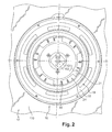
- Collar 3 of this container 1, shown in FIG. figure 3 receives an inner sleeve 3 'provided with a peripheral edge 4, continuous and extending radially outwardly. This edge therefore defines a continuous circular lip 4. The free end of this lip 4 is folded inwards, forming a groove 4 'visible for example at the figure 6 .
- the lip 4 defines a first peripheral flange 5, annular and fixed on the neck 3.
- This flange 5 is provided with tabs 6 extending radially outwardly from the periphery of the flange 5, as illustrated in FIGS. figures 1 and 3 .
- the cover 2 is configured in relief extending inwardly of the container 1, as shown in FIGS. Figures 1, 3 to 5 .
- the central inner part 7 of the lid 2 is of a diameter slightly smaller than the inside diameter of the sleeve 3. In this way, the part 7 fits into the neck 3 and closes the latter tightly thanks to an annular seal 8, visible to Figures 8 to 10 and inserted into the groove 4 '.
- This inner portion 7 is recessed relative to a plane P tangential to an upper face of the flange 5, as illustrated in FIG. figure 3 .
- the portion 7 comprises an annular upper edge shaped as a peripheral flange 9 directed towards the center of the lid 2.
- This flange 9 is parallel to the plane P and located substantially at the level of the lip 4.
- the flange 9 is concentric with the flange 5.
- the peripheral flange 9 is regularly provided with notches 10 and lugs 10 'allowing access to the available space between the flange 9 and the bottom 11 of the inner part 7 of the cover 2.
- the flange 9 is adapted so that its periphery external, continuous, or in sealing support against the gasket 8.
- the bottom 11 of the lid 2 is equipped in the central part, with a connecting member or embossment 12 in relief.
- this imprint 12 reproduces the name of the applicant with a particular graphic.
- this imprint 12 comprises an alphanumeric code 121 and a peripheral rib 122. Alternatively, it may be another geometric shape, for example a decorative pattern.
- This relief 12 protrudes protruding from the bottom 11 in the direction of the plane P. It thus forms a connecting member 12 of predefined geometry.
- Flanges 5 and 9 define two bayonet type connection systems, known per se. These systems are concentric.
- the flange 5 is oriented towards the outside of the neck 3 and allows a connection of the latter with an enclosure other than the container 1.
- the other flange 9 is oriented towards the inside of the neck 3 and allows the connection of the cover 2 with a door of the enclosure.
- the inner portion 7 is provided on its outer edge, pins.
- a pin 13 is partially visible at the figure 6 .
- Several lugs 13 extend radially outwardly of the portion 7 and are distributed on its periphery. These lugs 13 are inserted in slots 14 visible in particular at the figure 6 when the lid is locked in the neck 3.
- the slots 14 are formed in the wall of the sleeve 3 '. These slots 14 are configured in L.
- the large branch 140 of each slot 14 is located near the top of the neck 3 and oriented parallel to the plane P. These slots 14 allow the reception of the lugs 13 in the small branches 141 of the slots 14 which are oriented in a direction parallel to a longitudinal axis AA 'of the container.
- the operation of the lid 2 can not be easily performed manually or with a tool usually available, for example a clamp or a screwdriver.
- a connecting member or impression 15 complementary in shape to that of the cavity 12, the reliefs and recesses will cooperate with the recesses and reliefs of the cavity 12 of the cover 2 in order to be able to maneuver it.
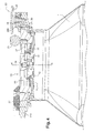
- a connecting member 15 of complementary shape is shown in FIG. figure 2 , in the central part of the door 16 of an enclosure 17.
- the impression 15 comprises an alphanumeric pattern 151 of complementary shape to the pattern 121 and a complementary edge 152 of the inner edge of the rib 122.
- This door 16 equips a wall 170 of an enclosure 17, as schematically represented in FIG. figure 2 .
- Such enclosures 17 are known per se. They can be provided with several doors 16 each equipped with the same footprint 15. In a variant, the same enclosure 17 can be equipped with several doors 16, each door 16 having a specific footprint 15 adapted to the connection with a type of receptacle. For the clarity of the presentation and the readability of the figures, only the door 16 is shown in FIGS. Figures 3 to 10 .
- a tool for example a hand tool, equipped with an end provided with a recess 15 complementary to that of the cavity 12 located on the lid 2.
- a tool allows , if necessary, the opening and closing of the container 1, for certain maintenance or cleaning operations of the container 1.
- the lid 2 of the container 1 must, in order to be manoeuvrable, be connected to a device provided with a recess 15 of complementary shape to that of the imprint 12 present on the lid 2.
- the door 16, illustrated at figure 2 has a shape complementary to the lid 2 of the container 1 illustrated in FIG. figure 1 .
- the location of the door 16 in the wall 170 is delimited by a flange 18, annular, fixed on the wall 170 of the enclosure 17 and parallel to a main plane P 'of the door 16 shown in FIG. figure 3 and which is tangent to an outer face of the wall 170 when the door 16 is closed.
- This flange 18 is equipped with notches 19 which thus provide, between the flange 18 and the wall 170, a space adapted to receive the tabs 6, of the outer flange 5 of the cover 2.
- a connection system is thus produced. bayonet type, between the enclosure 17 and the container 1. This first connection allows to secure the speakers independently of a second connection between the door 16 and the cover 2.
- the door 16 of the enclosure 17 is also equipped with a so-called central flange 20, of smaller diameter than the flange 18 and concentric with the latter when the door 16 is closed.
- This flange 20 is provided with lugs 21 regularly spaced and extending radially towards the outside of the door 16, parallel to the main plane P '. These tabs 21 are separated by recesses 21 '.
- the flange 20 has dimensions adapted to engage in the space available between the bottom 11 of the cover 2 and the flange 9, at the notches 10 of the flange 9.
- the door 16 has dimensions and a configuration corresponding to those of the lid 2.
- the inner portion 7 of the lid 2 is equipped with the flange 9 which cooperates with the flange 20 of the door 16, so as to ensure the fastening of the door 16 and the cover 2.
- a second connection system also of the bayonet type, is thus produced for connecting the doors 2, 16 to one another, independently of the connection of the container 1 and the enclosure 17.
- the door 16 and the lid 2 are pressed against each other, with an air mattress between the two as thin as possible.
- the impressions 12, 15 of complementary shapes cooperate.
- the impression 15 extends outside the door 16 beyond the plane P ', as illustrated in FIG. figure 3 .
- the height H 15 of the recess 15, on which it protrudes with respect to the plane P 'of the door 16 is such that it is not possible to have a contact, over the entire surface, between the door 16 and the lid of a container, in the case where the lid is not hollow and provided with an imprint 12 of shape complementary to that of the imprint 15.
- the door 16 and the cover 12 When the door 16 and the cover 12 are secured, they must be maneuvered to access the interior of the container 1 and / or the enclosure 17.
- the door 16 of the enclosure 17 is mounted on a hinge 22 positioned on the inner face of the wall 170 of the enclosure 17.
- a button operation 23 opens the door 16, which consequently opens towards the interior of the enclosure 17.
- This safety member or lock 25 makes it possible to keep the door 16 in the locked position, for example when the enclosure 17 is not connected to another predefined enclosure, such as the container 1. This safety member 25 also prevents accidental separation between the speakers 17 and 1 connected, when the door 16 and the lid 2 are in open positions.
- this safety member 25 is fixed to the wall 170 of the enclosure 17. It comprises an operating arm 26 for its rotation around a geometric axis BB 'perpendicular to the inner face 24 of the door 16 and on the plane P '.
- this latch 25 prevents any opening of the door.
- a pull on the button 23 in the direction of the arrow F1 to the figure 6 does not open the door 16, the finger 27 preventing this movement.
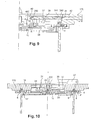
- the main body 28 of the lock 25 is also provided with a helical groove 29 extending towards the inside of the body 28, from the lower face of the body 28 which bears against the wall 170 of the enclosure 17.
- the throat 29 is visible to figures 6 and 8 .
- the deepest portion 290 of the groove 29 is located above a rod 30.
- This rod 30 is oriented parallel to the axis B-B '.
- the rod 30 is disposed in a well 31 formed in the wall 170 of the enclosure 17.
- the rod 30 comprises a collar 32 extending radially towards the walls of the well 31.
- the rod 30 is equipped with a return member 33, in this case a coil spring.
- the rod 30 is movable in translation in the well 31. Its movement, in one direction, namely towards the body 28, is effected under the action of the spring 33 and its displacement, in the opposite direction, is carried out against the return force of the spring 33, by pressing the ramp 29 on the rod 30.
- the bottom of the well 31 is located above the flange 18 surrounding the door 16, more precisely above the space receiving the tabs 6 of the flange 5 of the cover 2.
- the bottom of the well 31 is pierced.
- the well 31 opens out under the flange 18.
- the opening in the bottom of the well is adapted to allow the single passage of the rod 30.
- the groove 29 is supported, at its area 290 of great depth, on the rod 30 but without moving it towards the bottom of the well 31. In other words, the lower end of the rod 30 does not open into the space under the flange 18.
- the body 28 of the lock 25 has pivoted and the finger 27 is no longer supported on the inner face 24 of the door 16.
- the finger 27 is oriented opposite the door 16, resting on the wall 170 of the enclosure 17. In this position, it no longer prohibits a maneuver opening the door 16.
- the shallower part 291 of the ramp 29 is then supported on the end of the rod 30. This has for effect of moving the rod 30 towards the bottom of the well 31. In this case, the lower end 300 of the rod 30 passes through the bottom of the well 31 and partially obstructs the space under the flange 18.
- the lock 25 is adapted to move from a first position where it prohibits the opening of the door 16 while allowing the disconnection between the enclosure 17 and the container 1, at a second position where it allows the opening of the door 16 while prohibiting the separation of connected speakers 1, 17.
- These positions are obtained by rotating in rotation about the axis BB 'of a receiving housing of variable depth, in this case the groove 29, this housing being adapted to receive a locking member movable in translation, in this case the rod 30. It is possible, for safety, to view the positions of the lock 25 corresponding to the opening and locking of the door 16, for example by a visual marking on the finger 27 and the face 24 of the door 16.
- the impression 15 of the door 16 of the enclosure 17 is mounted free to rotate about an axis represented by a central shaft 34 inserted in a housing 35 formed in the thickness of the door 16 as illustrated in FIGS. Figures 8 to 10 .
- This shaft 34 is oriented in a direction perpendicular to the inner face 24 of the door 16.
- the shaft 34 is thus parallel to the axis BB 'of the latch 25, when the door 16 is closed.
- the longitudinal axis of the shaft 34 coincides with the longitudinal axis AA 'of the neck 3, when the container 1 is connected to the enclosure 17.
- Lateral wings 36 located at the base of the recess 15 bear on the inner face of the wall of the housing 35, so as to avoid an output of the cavity 15 out of its housing 35.
- a piece 37 flat disk-shaped is positioned between the bottom of the housing 35 and the wings 36. This piece 37 is partially inserted into the central zone 350 of the door 16 receiving the shaft 34. This piece 37 is integral with the wings 36 to hold them in abutment against the wall of the housing 35. The impression 15 is immobilized in translation in its housing 35, while being guided in rotation.
- This piece 37 is a constituent part of the door 16 and is provided with at least one slot 38 in an arc.
- the annular piece is equipped with two slots 38 in an arc so the concavities are oriented in opposite directions.
- these slots 38 are arranged at 120 ° relative to each other.
- the number of slots 38 is different, for example it is three.
- they can be arranged differently, for example at 180 °.
- Two locking bars 39 are inserted, at one end 390, into two supports 40, the base 400 of each support 40 being housed in a slot 38.
- Each base 400 is integral with a wing 36 of the impression 15.
- the displacement of each support 40 in a slot 38 is under the direct action of the rotational movement of the cavity 15 via the integral movement of the wings 36, the base 400 and the part 37.
- the housings 41 are also arranged at 120 ° relative to each other. This movement is carried out in two housings 41, of section adapted to allow the translational movement of the locking bars 39.
- the housings 41 are also arranged at 120 ° relative to each other. This displacement is guided by reliefs 391 located near a free end 392 of each bar 39. These reliefs 391 slide in a portion of the housing 41. These housings 41 extend over a length greater than the length of the bars 39 and open on the peripheral edge of the door 16.
- a housing 42 of the same size as a housing 41 and also opening on the peripheral wall of the opening in which the door 16 is located is arranged opposite each housing 41.
- two housings 42 formed in the wall 170 of the enclosure 17 extend the housings 41 formed in the door 16.
- These housings 41 and 42 are respectively arranged parallel to the inner face 24 of the door 16 and the wall 170 of the enclosure 17, when the door 16 is closed.
- the disposition of the slots 38 makes it possible to move the locking bars 39 in different directions during the same rotation of the impression 15. If this displacement takes place in different directions, the direction of movement of the bars 39 is the even.
- the rotation of the recess 15 makes it possible to push the bars 39 from the recesses 41 towards the recesses 42, the two bars 39 being moved simultaneously toward the recesses 42.
- each bar 39 has a length of the housings 41 when they are in the maximum advance position, that is to say when the supports 40 are located at the end of the slots 38 which are the farthest from the central shaft 34.
- the end portion 392 of each bar 39 extending outside the housing 41 is, in this case, housed in the housing 42 corresponding when the door 16 is closed.
- the bars 39 reach, by rotation of the cavity 15, a locking position of the closed door. This locking makes it possible to keep the door 16 closed, whether the safety member 25 is in the closed position or not.
- the position of the footprint 15, which is accessible and operable only from outside the enclosure 17, allows for optimal locking of the door 16. It can then be unlocked only from the outside of the enclosure 17 by rotation of the cavity 15, this rotation being possible only if a complementary cavity 12 is connected to the cavity 15.
- the members 15, 12 make it possible, on the one hand, to ensure a connection between a predetermined enclosure 17 and a container 1 and, on the other hand, to prevent the operations of the door 16 and the cover 2 between doors 16, 2 of complementary shapes.
- the configuration of the imprints 12, 15 makes it possible to identify the position in which the two enclosures 1, 17 must be presented to be secured.
- the members 12, 15 also constitute a key for the connection of the two enclosures 1, 17.
- the cavity 12 of the lid 2 of the container 1 is positioned facing the cavity 15 of the door 16 of the enclosure 17 in a position where the complementary reliefs can come into mutual engagement.
- the pattern 151 of the imprint 15 is inserted in the pattern 121 of the imprint 12, the edge 152 cooperating with the rib 122.
- the imprints 12, 15 comprise only a pattern 121, 122, 151, 152 cooperating with a complementary pattern 151, 152, 121, 122.
- the so-called male footprint 15 of the door 16 of the enclosure 17 is inserted into the so-called female footprint 12 of the lid 2 of the container 1.
- the positions of male and female fingerprints can be reversed, the male fingerprint being, not on the door 16 of the chamber 17, but on the lid 2 of the container 1.
- the male fingerprint is also positive, it is that is to say, the embossed imprint and negative the female imprint 12, that is to say the intaglio imprint, with the alphanumeric code and / or the shape in the mirror position.
- This first rotational movement is nevertheless not sufficient to cause the connection of the door 16 and the cover 2 to be connected, although the impression 15 has initiated a rotation driven by the fixed impression 12 of the cover 2.
- the door 16 of the enclosure 17 is always locked in the closed position by the bars 39 inserted in the housings 42 formed in the wall 170 of the enclosure 17. This blocking of the door 16 is also secured by the lock 25, which is in a position of locking where the finger 27 is supported on the door 16. In this configuration, the closing of the door 16 is secured.
- each support 40 is, at the end of its displacement in the slot 38, at the end located near the central shaft 34.
- the bars 39 then no longer protrude beyond the periphery of the door 16. This authorizes the operation of the door 16 of the enclosure, the latter being no longer locked in the closed position by the bars 39 which are no longer inserted in the housings 42. Only the lock 25 still ensures the locking in the closed position of the door 16.
- the container 1 may be rotated relative to the cover 2, on a low stroke, corresponding substantially to the length of the branches 140 of the notches 14.
- the cover 2 and the door 16 are immobile in rotation, by compared to the container 1, while it can rotate.
- the lid 2 of the neck 3 of the container is detached.
- the lid 2 can then be easily removed by pulling along the arrow F1 to the figure 6 when opening the door 16 to which it is connected.
- the cover 2 and the door 16 are in the unlocked position, that is to say respectively disengaged from the neck 3 of the container 1 and the wall 170 in the enclosure 17.
- connection device has been made, sealed, secure, while preserving the sterility of the interior of the two enclosures 1, 17.
Landscapes
- Physics & Mathematics (AREA)
- Engineering & Computer Science (AREA)
- General Engineering & Computer Science (AREA)
- High Energy & Nuclear Physics (AREA)
- Closures For Containers (AREA)
- Seal Device For Vehicle (AREA)
- Clamps And Clips (AREA)
Applications Claiming Priority (1)
| Application Number | Priority Date | Filing Date | Title |
|---|---|---|---|
| FR0800740A FR2927464B1 (fr) | 2008-02-12 | 2008-02-12 | Dispositif de connexion etanche entre deux enceintes |
Publications (2)
| Publication Number | Publication Date |
|---|---|
| EP2091051A1 true EP2091051A1 (de) | 2009-08-19 |
| EP2091051B1 EP2091051B1 (de) | 2011-04-13 |
Family
ID=39828473
Family Applications (1)
| Application Number | Title | Priority Date | Filing Date |
|---|---|---|---|
| EP09356007A Active EP2091051B1 (de) | 2008-02-12 | 2009-02-11 | Behälter mit einer Vorrichtung zur dichten Verbindung zwischen zwei Behältern |
Country Status (5)
| Country | Link |
|---|---|
| EP (1) | EP2091051B1 (de) |
| AT (1) | ATE505795T1 (de) |
| DE (1) | DE602009001010D1 (de) |
| ES (1) | ES2364026T3 (de) |
| FR (1) | FR2927464B1 (de) |
Cited By (14)
| Publication number | Priority date | Publication date | Assignee | Title |
|---|---|---|---|---|
| WO2011023906A1 (fr) * | 2009-08-26 | 2011-03-03 | Bernard Saint Martin | Dispositif de jonction temporaire étanche à double porte |
| WO2011061464A1 (fr) | 2009-11-23 | 2011-05-26 | Sartorius Stedim Aseptics | Enceinte pour dispositif de jonction etanche et dispositif de transfert aseptique. |
| WO2011061463A1 (fr) | 2009-11-23 | 2011-05-26 | Sartorius Stedim Aseptics | Perfectionnements a la jonction etanche et au transfert etanche entre deux enceintes en vue d'un transfert aseptique entre elles. |
| WO2013053844A1 (fr) * | 2011-10-14 | 2013-04-18 | Getinge La Calhene | Mecanisme de commande a haut niveau de securite pour un dispositif de transfert etanche entre deux volumes clos |
| WO2013110745A1 (fr) * | 2012-01-27 | 2013-08-01 | Charles Glachet | Ensemble d'une cellule et d'un conteneur adaptable sur la cellule |
| WO2014172665A1 (en) * | 2013-04-19 | 2014-10-23 | Delaware Capital Formation, Inc. | Sealed transfer port with interlocks |
| EP2946833A1 (de) | 2014-05-20 | 2015-11-25 | JCE Biotechnology | Dichte verbindungsvorrichtung zwischen zwei behältern |
| WO2016156419A1 (fr) | 2015-03-30 | 2016-10-06 | Lourd'innov | Sachet pour le transfert et l'emballage de composants d'une enceinte confinee |
| FR3041271A1 (fr) * | 2015-09-22 | 2017-03-24 | Jce Biotechnology | Dispositif de connexion etanche entre deux enceintes |
| FR3071725A1 (fr) * | 2017-10-03 | 2019-04-05 | Sartorius Stedim Fmt Sas | Dispositif de jonction etanche pour le transfert aseptique d’un produit biopharmaceutique entre une enceinte et un conteneur |
| US11034477B2 (en) | 2016-02-26 | 2021-06-15 | Schott Ag | Method of transferring a plurality of containers and/or closure elements into a clean room, transport and packaging container and packaging structure therefore |
| WO2021123687A1 (fr) * | 2019-12-20 | 2021-06-24 | Abc Transfer | Conteneur etanche pourvu d'une bride bi-matiere |
| DE102021130404A1 (de) | 2020-11-23 | 2022-05-25 | Jce Biotechnology | Dichte Vorrichtung, die Zugang zu einem Gehäuse bietet, sowie entsprechendes System zur dichten Verbindung zwischen zwei Gehäusen |
| FR3124414A1 (fr) | 2021-06-23 | 2022-12-30 | Jce Biotechnology | Installation de préparation d’un produit centrifugé, ainsi que procédé de préparation correspondant utilisant une telle installation |
Citations (7)
| Publication number | Priority date | Publication date | Assignee | Title |
|---|---|---|---|---|
| GB2038921A (en) * | 1978-11-06 | 1980-07-30 | Atomic Energy Authority Uk | Interlocking Container Doors |
| FR2496325A1 (fr) | 1980-12-16 | 1982-06-18 | Calhene | Dispositif de securite pour systeme de verrouillage entre deux enceintes etanches |
| GB2102719A (en) * | 1981-07-17 | 1983-02-09 | Atomic Energy Authority Uk | Posting system |
| GB2109719A (en) | 1981-11-18 | 1983-06-08 | Allied Steel Wire Ltd | Cold working of metal rod or wire |
| GB2218663A (en) | 1987-12-22 | 1989-11-22 | Atomic Energy Authority Uk | Lid system |
| FR2695343A1 (fr) | 1992-09-04 | 1994-03-11 | Sne Calhene | Mécanisme de commande centralisé, à sécurités incorporées, pour un dispositif de transfert étanche entre deux volumes clos. |
| EP0688020A1 (de) | 1994-06-17 | 1995-12-20 | I D C - Isolateur Denominateur Commun | Abgedichtete Andockeinrichtung zwischen zwei umweltisolierten Gehäusen |
-
2008
- 2008-02-12 FR FR0800740A patent/FR2927464B1/fr active Active
-
2009
- 2009-02-11 DE DE602009001010T patent/DE602009001010D1/de active Active
- 2009-02-11 ES ES09356007T patent/ES2364026T3/es active Active
- 2009-02-11 EP EP09356007A patent/EP2091051B1/de active Active
- 2009-02-11 AT AT09356007T patent/ATE505795T1/de not_active IP Right Cessation
Patent Citations (7)
| Publication number | Priority date | Publication date | Assignee | Title |
|---|---|---|---|---|
| GB2038921A (en) * | 1978-11-06 | 1980-07-30 | Atomic Energy Authority Uk | Interlocking Container Doors |
| FR2496325A1 (fr) | 1980-12-16 | 1982-06-18 | Calhene | Dispositif de securite pour systeme de verrouillage entre deux enceintes etanches |
| GB2102719A (en) * | 1981-07-17 | 1983-02-09 | Atomic Energy Authority Uk | Posting system |
| GB2109719A (en) | 1981-11-18 | 1983-06-08 | Allied Steel Wire Ltd | Cold working of metal rod or wire |
| GB2218663A (en) | 1987-12-22 | 1989-11-22 | Atomic Energy Authority Uk | Lid system |
| FR2695343A1 (fr) | 1992-09-04 | 1994-03-11 | Sne Calhene | Mécanisme de commande centralisé, à sécurités incorporées, pour un dispositif de transfert étanche entre deux volumes clos. |
| EP0688020A1 (de) | 1994-06-17 | 1995-12-20 | I D C - Isolateur Denominateur Commun | Abgedichtete Andockeinrichtung zwischen zwei umweltisolierten Gehäusen |
Cited By (33)
| Publication number | Priority date | Publication date | Assignee | Title |
|---|---|---|---|---|
| US8893914B2 (en) | 2009-08-26 | 2014-11-25 | Lourd 'Innov SAS | Temporary sealed double-door junction device |
| FR2949599A1 (fr) * | 2009-08-26 | 2011-03-04 | Martin Bernard Saint | Dispositif de jonction temporaire etanche a double porte |
| WO2011023906A1 (fr) * | 2009-08-26 | 2011-03-03 | Bernard Saint Martin | Dispositif de jonction temporaire étanche à double porte |
| WO2011061464A1 (fr) | 2009-11-23 | 2011-05-26 | Sartorius Stedim Aseptics | Enceinte pour dispositif de jonction etanche et dispositif de transfert aseptique. |
| WO2011061463A1 (fr) | 2009-11-23 | 2011-05-26 | Sartorius Stedim Aseptics | Perfectionnements a la jonction etanche et au transfert etanche entre deux enceintes en vue d'un transfert aseptique entre elles. |
| US9283556B2 (en) | 2009-11-23 | 2016-03-15 | Sartorius Stedim Aseptics | Tight connection and tight transfer between two housings in view of an aseptic transfer therebetween |
| US9168520B2 (en) | 2009-11-23 | 2015-10-27 | Sartorius Stedim Aseptics | Chamber for sealed junction device and aseptic transfer device |
| RU2604454C2 (ru) * | 2011-10-14 | 2016-12-10 | Жетинж Ла Кален | Высокозащищенный механизм управления устройства для герметичного соединения двух замкнутых пространств |
| FR2981386A1 (fr) * | 2011-10-14 | 2013-04-19 | Getinge La Calhene | Mecanisme de commande a haut niveau de securite pour un dispositif de transfert etanche entre deux volumes clos |
| CN103987460A (zh) * | 2011-10-14 | 2014-08-13 | 洁定莱克琳公司 | 用于在两个封闭空间之间进行密封转移的装置的高度安全性控制机构 |
| US9704607B2 (en) | 2011-10-14 | 2017-07-11 | Getinge La Calhene | Highly safe control mechanism for a device for the sealed transfer between two closed spaces |
| CN103987460B (zh) * | 2011-10-14 | 2015-09-30 | 洁定莱克琳公司 | 用于在两个封闭空间之间进行密封转移的装置的高度安全性控制机构 |
| WO2013053844A1 (fr) * | 2011-10-14 | 2013-04-18 | Getinge La Calhene | Mecanisme de commande a haut niveau de securite pour un dispositif de transfert etanche entre deux volumes clos |
| WO2013110745A1 (fr) * | 2012-01-27 | 2013-08-01 | Charles Glachet | Ensemble d'une cellule et d'un conteneur adaptable sur la cellule |
| FR2986364A1 (fr) * | 2012-01-27 | 2013-08-02 | Charles Glachet | Dispositif a baionnette pour le raccordement d'un conteneur sur une bride de cellule |
| WO2014172665A1 (en) * | 2013-04-19 | 2014-10-23 | Delaware Capital Formation, Inc. | Sealed transfer port with interlocks |
| EP2946833A1 (de) | 2014-05-20 | 2015-11-25 | JCE Biotechnology | Dichte verbindungsvorrichtung zwischen zwei behältern |
| US10807771B2 (en) | 2015-03-30 | 2020-10-20 | Lourde'Innov | Bag for transferring and packaging components of a contained enclosure |
| WO2016156419A1 (fr) | 2015-03-30 | 2016-10-06 | Lourd'innov | Sachet pour le transfert et l'emballage de composants d'une enceinte confinee |
| FR3041271A1 (fr) * | 2015-09-22 | 2017-03-24 | Jce Biotechnology | Dispositif de connexion etanche entre deux enceintes |
| EP3147026A1 (de) | 2015-09-22 | 2017-03-29 | JCE Biotechnology | Dichte verbindungsvorrichtung zwischen zwei behältern |
| US11034477B2 (en) | 2016-02-26 | 2021-06-15 | Schott Ag | Method of transferring a plurality of containers and/or closure elements into a clean room, transport and packaging container and packaging structure therefore |
| FR3071725A1 (fr) * | 2017-10-03 | 2019-04-05 | Sartorius Stedim Fmt Sas | Dispositif de jonction etanche pour le transfert aseptique d’un produit biopharmaceutique entre une enceinte et un conteneur |
| WO2019068963A1 (fr) * | 2017-10-03 | 2019-04-11 | Sartorius Stedim Fmt Sas | Dispositif de jonction etanche pour le transfert aseptique d'un produit biopharmaceutique entre une enceinte et un conteneur |
| US11684913B2 (en) | 2017-10-03 | 2023-06-27 | Sartorius Stedim Fmt Sas | Tight connection device for the aseptic transfer of a biopharmaceutical product between a chamber and a container |
| WO2021123687A1 (fr) * | 2019-12-20 | 2021-06-24 | Abc Transfer | Conteneur etanche pourvu d'une bride bi-matiere |
| FR3105023A1 (fr) * | 2019-12-20 | 2021-06-25 | Abc Transfer | Conteneur etanche pourvu d’une bride bi-matiere |
| CN115151343A (zh) * | 2019-12-20 | 2022-10-04 | Abc传送 | 配备有双材料法兰的密封容器 |
| DE102021130404A1 (de) | 2020-11-23 | 2022-05-25 | Jce Biotechnology | Dichte Vorrichtung, die Zugang zu einem Gehäuse bietet, sowie entsprechendes System zur dichten Verbindung zwischen zwei Gehäusen |
| FR3116645A1 (fr) | 2020-11-23 | 2022-05-27 | Jce Biotechnology | Dispositif étanche donnant accès à une enceinte, ainsi que système correspondant de connexion étanche entre deux enceintes |
| US11901092B2 (en) | 2020-11-23 | 2024-02-13 | Jce Biotechnology | Tight device giving access to an enclosure, as well as a corresponding tight connection system between two enclosures |
| FR3124414A1 (fr) | 2021-06-23 | 2022-12-30 | Jce Biotechnology | Installation de préparation d’un produit centrifugé, ainsi que procédé de préparation correspondant utilisant une telle installation |
| EP4115977A1 (de) | 2021-06-23 | 2023-01-11 | JCE Biotechnology | Anlage zur herstellung eines zentrifugierten produkts sowie entsprechendes herstellungsverfahren unter verwendung einer solchen anlage |
Also Published As
| Publication number | Publication date |
|---|---|
| ATE505795T1 (de) | 2011-04-15 |
| EP2091051B1 (de) | 2011-04-13 |
| FR2927464A1 (fr) | 2009-08-14 |
| FR2927464B1 (fr) | 2014-08-15 |
| DE602009001010D1 (de) | 2011-05-26 |
| ES2364026T3 (es) | 2011-08-23 |
Similar Documents
| Publication | Publication Date | Title |
|---|---|---|
| EP2091051B1 (de) | Behälter mit einer Vorrichtung zur dichten Verbindung zwischen zwei Behältern | |
| EP2760771B1 (de) | Mechanismus mit vereinfachter handhabung zur steuerung einer vorrichtung zur dichten verbindung von zwei eingeschlossenen räumen | |
| EP3042382B1 (de) | Vorrichtung zur bereitstellung einer fluiddichten verbindung mit verbesserter betriebssicherheit | |
| EP1938717B1 (de) | Druckkochgerät mit einer Verriegelung | |
| EP3042381B1 (de) | Flüssigkeitsdichte kammer mit einem öffnungs- und schliesssteuerungsmechanismus für eine vorrichtung zur bereitstellung einer fluiddichten verbindung zwischen zwei eingeschlossenen volumen | |
| EP2394547B1 (de) | Elektrohaushaltsgerät zur Essenszubereitung, das aus einem mit einem abnehmbaren Deckel verschlossenen Arbeitsbehälter besteht | |
| WO2011061463A1 (fr) | Perfectionnements a la jonction etanche et au transfert etanche entre deux enceintes en vue d'un transfert aseptique entre elles. | |
| EP0761558B1 (de) | Vorrichtung zum Verschliessen eines Behälters und zur Abgabe des Behälterinhalts | |
| EP3042380B1 (de) | Vorrichtung zur bereitstellung einer fluiddichten verbindung in zwei eingeschlossenen volumina mit vorrichtung zum halten vor der verbindung | |
| EP2504102B1 (de) | Gehäuse für dichte verbindungsvorrichtung und aseptische transfervorrichtung | |
| EP2471075B1 (de) | Provisorisch abgedichtete doppeltürverbindungsvorrichtung | |
| EP1566129B1 (de) | Elektrisches Haushaltsgerät zur Nahrungszubereitung | |
| FR2735201A1 (fr) | Couvercle a placer sur une porte d'un recipient a steriliser | |
| EP1018917B1 (de) | Sicherheitsvorrichtung für ein elektrisches haushaltsgerät zum anwenden in der küche, und gerät mit einer solchen vorrichtung | |
| EP3049345B1 (de) | Deckel zum verschliessen einer schachtel und anordnung aus einer schachtel und solch einem deckel | |
| EP1153563A1 (de) | Haushaltsgerät zur Nahrungszubereitung mit einer Klauenverriegelungsvorrichtung eines Deckels auf einem Behälter | |
| FR2613526A1 (fr) | Dispositif deconnectable pour mettre en communication deux volumes clos | |
| FR2717361A1 (fr) | Dispositif de sécurité pour un appareil de préparation des aliments. | |
| EP3049346A1 (de) | Deckel mit einer dichtung zum verschliessen einer dose sowie anordnung aus einer dose und solch einem deckel | |
| FR2913964A1 (fr) | Dispositif de solidarisation d'au moins un element d'outillage de transfert, etoile, guide entree/sortie et element formant cavite correspondants. | |
| EP4067295A1 (de) | Getränkeausgabemaschine mit einem deckel zum verschliessen einer kammer zur aufnahme eines getränkebehälters wie z. b. eines fasses | |
| FR2704210A1 (fr) | Dispositif de fixation d'un couvercle sur un conteneur utilisable à distance à l'aide d'un bras manipulateur. | |
| FR2893930A1 (fr) | Dispositif d'aide a la rotation d'au moins un conteneur. |
Legal Events
| Date | Code | Title | Description |
|---|---|---|---|
| PUAI | Public reference made under article 153(3) epc to a published international application that has entered the european phase |
Free format text: ORIGINAL CODE: 0009012 |
|
| AK | Designated contracting states |
Kind code of ref document: A1 Designated state(s): AT BE BG CH CY CZ DE DK EE ES FI FR GB GR HR HU IE IS IT LI LT LU LV MC MK MT NL NO PL PT RO SE SI SK TR |
|
| AX | Request for extension of the european patent |
Extension state: AL BA RS |
|
| 17P | Request for examination filed |
Effective date: 20091006 |
|
| 17Q | First examination report despatched |
Effective date: 20091201 |
|
| AKX | Designation fees paid |
Designated state(s): AT BE BG CH CY CZ DE DK EE ES FI FR GB GR HR HU IE IS IT LI LT LU LV MC MK MT NL NO PL PT RO SE SI SK TR |
|
| GRAP | Despatch of communication of intention to grant a patent |
Free format text: ORIGINAL CODE: EPIDOSNIGR1 |
|
| RTI1 | Title (correction) |
Free format text: ENCLOSURE COMPRISING A DEVICE ADAPTED TO MAKE A WATERTIGHT CONNECTION BETWEEN TWO ENCLOSURES |
|
| GRAS | Grant fee paid |
Free format text: ORIGINAL CODE: EPIDOSNIGR3 |
|
| GRAA | (expected) grant |
Free format text: ORIGINAL CODE: 0009210 |
|
| AK | Designated contracting states |
Kind code of ref document: B1 Designated state(s): AT BE BG CH CY CZ DE DK EE ES FI FR GB GR HR HU IE IS IT LI LT LU LV MC MK MT NL NO PL PT RO SE SI SK TR |
|
| REG | Reference to a national code |
Ref country code: GB Ref legal event code: FG4D Free format text: NOT ENGLISH |
|
| REG | Reference to a national code |
Ref country code: CH Ref legal event code: EP |
|
| REG | Reference to a national code |
Ref country code: IE Ref legal event code: FG4D Free format text: LANGUAGE OF EP DOCUMENT: FRENCH |
|
| REF | Corresponds to: |
Ref document number: 602009001010 Country of ref document: DE Date of ref document: 20110526 Kind code of ref document: P |
|
| REG | Reference to a national code |
Ref country code: DE Ref legal event code: R096 Ref document number: 602009001010 Country of ref document: DE Effective date: 20110526 |
|
| REG | Reference to a national code |
Ref country code: NL Ref legal event code: T3 |
|
| REG | Reference to a national code |
Ref country code: ES Ref legal event code: FG2A Ref document number: 2364026 Country of ref document: ES Kind code of ref document: T3 Effective date: 20110823 |
|
| LTIE | Lt: invalidation of european patent or patent extension |
Effective date: 20110413 |
|
| PG25 | Lapsed in a contracting state [announced via postgrant information from national office to epo] |
Ref country code: LT Free format text: LAPSE BECAUSE OF FAILURE TO SUBMIT A TRANSLATION OF THE DESCRIPTION OR TO PAY THE FEE WITHIN THE PRESCRIBED TIME-LIMIT Effective date: 20110413 Ref country code: SE Free format text: LAPSE BECAUSE OF FAILURE TO SUBMIT A TRANSLATION OF THE DESCRIPTION OR TO PAY THE FEE WITHIN THE PRESCRIBED TIME-LIMIT Effective date: 20110413 Ref country code: HR Free format text: LAPSE BECAUSE OF FAILURE TO SUBMIT A TRANSLATION OF THE DESCRIPTION OR TO PAY THE FEE WITHIN THE PRESCRIBED TIME-LIMIT Effective date: 20110413 Ref country code: PT Free format text: LAPSE BECAUSE OF FAILURE TO SUBMIT A TRANSLATION OF THE DESCRIPTION OR TO PAY THE FEE WITHIN THE PRESCRIBED TIME-LIMIT Effective date: 20110816 Ref country code: NO Free format text: LAPSE BECAUSE OF FAILURE TO SUBMIT A TRANSLATION OF THE DESCRIPTION OR TO PAY THE FEE WITHIN THE PRESCRIBED TIME-LIMIT Effective date: 20110713 |
|
| REG | Reference to a national code |
Ref country code: IE Ref legal event code: FD4D |
|
| PG25 | Lapsed in a contracting state [announced via postgrant information from national office to epo] |
Ref country code: FI Free format text: LAPSE BECAUSE OF FAILURE TO SUBMIT A TRANSLATION OF THE DESCRIPTION OR TO PAY THE FEE WITHIN THE PRESCRIBED TIME-LIMIT Effective date: 20110413 Ref country code: IS Free format text: LAPSE BECAUSE OF FAILURE TO SUBMIT A TRANSLATION OF THE DESCRIPTION OR TO PAY THE FEE WITHIN THE PRESCRIBED TIME-LIMIT Effective date: 20110813 Ref country code: GR Free format text: LAPSE BECAUSE OF FAILURE TO SUBMIT A TRANSLATION OF THE DESCRIPTION OR TO PAY THE FEE WITHIN THE PRESCRIBED TIME-LIMIT Effective date: 20110714 Ref country code: AT Free format text: LAPSE BECAUSE OF FAILURE TO SUBMIT A TRANSLATION OF THE DESCRIPTION OR TO PAY THE FEE WITHIN THE PRESCRIBED TIME-LIMIT Effective date: 20110413 Ref country code: CY Free format text: LAPSE BECAUSE OF FAILURE TO SUBMIT A TRANSLATION OF THE DESCRIPTION OR TO PAY THE FEE WITHIN THE PRESCRIBED TIME-LIMIT Effective date: 20110413 Ref country code: LV Free format text: LAPSE BECAUSE OF FAILURE TO SUBMIT A TRANSLATION OF THE DESCRIPTION OR TO PAY THE FEE WITHIN THE PRESCRIBED TIME-LIMIT Effective date: 20110413 Ref country code: SI Free format text: LAPSE BECAUSE OF FAILURE TO SUBMIT A TRANSLATION OF THE DESCRIPTION OR TO PAY THE FEE WITHIN THE PRESCRIBED TIME-LIMIT Effective date: 20110413 |
|
| PG25 | Lapsed in a contracting state [announced via postgrant information from national office to epo] |
Ref country code: IE Free format text: LAPSE BECAUSE OF FAILURE TO SUBMIT A TRANSLATION OF THE DESCRIPTION OR TO PAY THE FEE WITHIN THE PRESCRIBED TIME-LIMIT Effective date: 20110413 Ref country code: EE Free format text: LAPSE BECAUSE OF FAILURE TO SUBMIT A TRANSLATION OF THE DESCRIPTION OR TO PAY THE FEE WITHIN THE PRESCRIBED TIME-LIMIT Effective date: 20110413 |
|
| PLBE | No opposition filed within time limit |
Free format text: ORIGINAL CODE: 0009261 |
|
| STAA | Information on the status of an ep patent application or granted ep patent |
Free format text: STATUS: NO OPPOSITION FILED WITHIN TIME LIMIT |
|
| PG25 | Lapsed in a contracting state [announced via postgrant information from national office to epo] |
Ref country code: SK Free format text: LAPSE BECAUSE OF FAILURE TO SUBMIT A TRANSLATION OF THE DESCRIPTION OR TO PAY THE FEE WITHIN THE PRESCRIBED TIME-LIMIT Effective date: 20110413 Ref country code: PL Free format text: LAPSE BECAUSE OF FAILURE TO SUBMIT A TRANSLATION OF THE DESCRIPTION OR TO PAY THE FEE WITHIN THE PRESCRIBED TIME-LIMIT Effective date: 20110413 |
|
| 26N | No opposition filed |
Effective date: 20120116 |
|
| REG | Reference to a national code |
Ref country code: DE Ref legal event code: R097 Ref document number: 602009001010 Country of ref document: DE Effective date: 20120116 |
|
| PG25 | Lapsed in a contracting state [announced via postgrant information from national office to epo] |
Ref country code: MC Free format text: LAPSE BECAUSE OF NON-PAYMENT OF DUE FEES Effective date: 20120229 |
|
| PG25 | Lapsed in a contracting state [announced via postgrant information from national office to epo] |
Ref country code: MK Free format text: LAPSE BECAUSE OF FAILURE TO SUBMIT A TRANSLATION OF THE DESCRIPTION OR TO PAY THE FEE WITHIN THE PRESCRIBED TIME-LIMIT Effective date: 20110413 |
|
| PG25 | Lapsed in a contracting state [announced via postgrant information from national office to epo] |
Ref country code: BG Free format text: LAPSE BECAUSE OF FAILURE TO SUBMIT A TRANSLATION OF THE DESCRIPTION OR TO PAY THE FEE WITHIN THE PRESCRIBED TIME-LIMIT Effective date: 20110713 |
|
| PG25 | Lapsed in a contracting state [announced via postgrant information from national office to epo] |
Ref country code: MT Free format text: LAPSE BECAUSE OF FAILURE TO SUBMIT A TRANSLATION OF THE DESCRIPTION OR TO PAY THE FEE WITHIN THE PRESCRIBED TIME-LIMIT Effective date: 20110413 |
|
| PG25 | Lapsed in a contracting state [announced via postgrant information from national office to epo] |
Ref country code: TR Free format text: LAPSE BECAUSE OF FAILURE TO SUBMIT A TRANSLATION OF THE DESCRIPTION OR TO PAY THE FEE WITHIN THE PRESCRIBED TIME-LIMIT Effective date: 20110413 |
|
| PG25 | Lapsed in a contracting state [announced via postgrant information from national office to epo] |
Ref country code: LU Free format text: LAPSE BECAUSE OF NON-PAYMENT OF DUE FEES Effective date: 20120211 |
|
| PG25 | Lapsed in a contracting state [announced via postgrant information from national office to epo] |
Ref country code: HU Free format text: LAPSE BECAUSE OF FAILURE TO SUBMIT A TRANSLATION OF THE DESCRIPTION OR TO PAY THE FEE WITHIN THE PRESCRIBED TIME-LIMIT Effective date: 20090211 |
|
| REG | Reference to a national code |
Ref country code: FR Ref legal event code: PLFP Year of fee payment: 8 |
|
| REG | Reference to a national code |
Ref country code: FR Ref legal event code: PLFP Year of fee payment: 9 |
|
| PGFP | Annual fee paid to national office [announced via postgrant information from national office to epo] |
Ref country code: NL Payment date: 20170112 Year of fee payment: 9 |
|
| REG | Reference to a national code |
Ref country code: FR Ref legal event code: PLFP Year of fee payment: 10 |
|
| REG | Reference to a national code |
Ref country code: NL Ref legal event code: MM Effective date: 20180301 |
|
| PG25 | Lapsed in a contracting state [announced via postgrant information from national office to epo] |
Ref country code: NL Free format text: LAPSE BECAUSE OF NON-PAYMENT OF DUE FEES Effective date: 20180301 |
|
| PGFP | Annual fee paid to national office [announced via postgrant information from national office to epo] |
Ref country code: FR Payment date: 20230110 Year of fee payment: 15 |
|
| PGFP | Annual fee paid to national office [announced via postgrant information from national office to epo] |
Ref country code: IT Payment date: 20230208 Year of fee payment: 15 Ref country code: BE Payment date: 20230220 Year of fee payment: 15 |
|
| PGFP | Annual fee paid to national office [announced via postgrant information from national office to epo] |
Ref country code: ES Payment date: 20240306 Year of fee payment: 16 |
|
| PGFP | Annual fee paid to national office [announced via postgrant information from national office to epo] |
Ref country code: DE Payment date: 20240213 Year of fee payment: 16 Ref country code: CZ Payment date: 20240118 Year of fee payment: 16 Ref country code: GB Payment date: 20240221 Year of fee payment: 16 Ref country code: CH Payment date: 20240301 Year of fee payment: 16 |