EP2089937B1 - Verbinder - Google Patents
Verbinder Download PDFInfo
- Publication number
- EP2089937B1 EP2089937B1 EP07824432A EP07824432A EP2089937B1 EP 2089937 B1 EP2089937 B1 EP 2089937B1 EP 07824432 A EP07824432 A EP 07824432A EP 07824432 A EP07824432 A EP 07824432A EP 2089937 B1 EP2089937 B1 EP 2089937B1
- Authority
- EP
- European Patent Office
- Prior art keywords
- connector
- wires
- blade
- contacts
- cutting
- Prior art date
- Legal status (The legal status is an assumption and is not a legal conclusion. Google has not performed a legal analysis and makes no representation as to the accuracy of the status listed.)
- Active
Links
- 238000009413 insulation Methods 0.000 claims description 9
- 239000002184 metal Substances 0.000 claims description 3
- 230000005670 electromagnetic radiation Effects 0.000 claims description 2
- 239000011888 foil Substances 0.000 description 4
- 229910000842 Zamak Inorganic materials 0.000 description 3
- 230000006835 compression Effects 0.000 description 3
- 238000007906 compression Methods 0.000 description 3
- 239000004020 conductor Substances 0.000 description 3
- 239000000428 dust Substances 0.000 description 2
- 239000007769 metal material Substances 0.000 description 2
- 238000007792 addition Methods 0.000 description 1
- 230000004075 alteration Effects 0.000 description 1
- 230000005540 biological transmission Effects 0.000 description 1
- 239000000969 carrier Substances 0.000 description 1
- 238000006073 displacement reaction Methods 0.000 description 1
- 238000002955 isolation Methods 0.000 description 1
- 238000000034 method Methods 0.000 description 1
Images


Classifications
-
- H—ELECTRICITY
- H01—ELECTRIC ELEMENTS
- H01R—ELECTRICALLY-CONDUCTIVE CONNECTIONS; STRUCTURAL ASSOCIATIONS OF A PLURALITY OF MUTUALLY-INSULATED ELECTRICAL CONNECTING ELEMENTS; COUPLING DEVICES; CURRENT COLLECTORS
- H01R4/00—Electrically-conductive connections between two or more conductive members in direct contact, i.e. touching one another; Means for effecting or maintaining such contact; Electrically-conductive connections having two or more spaced connecting locations for conductors and using contact members penetrating insulation
- H01R4/24—Connections using contact members penetrating or cutting insulation or cable strands
- H01R4/2416—Connections using contact members penetrating or cutting insulation or cable strands the contact members having insulation-cutting edges, e.g. of tuning fork type
- H01R4/242—Connections using contact members penetrating or cutting insulation or cable strands the contact members having insulation-cutting edges, e.g. of tuning fork type the contact members being plates having a single slot
- H01R4/2425—Flat plates, e.g. multi-layered flat plates
- H01R4/2429—Flat plates, e.g. multi-layered flat plates mounted in an insulating base
- H01R4/2433—Flat plates, e.g. multi-layered flat plates mounted in an insulating base one part of the base being movable to push the cable into the slot
-
- H—ELECTRICITY
- H01—ELECTRIC ELEMENTS
- H01R—ELECTRICALLY-CONDUCTIVE CONNECTIONS; STRUCTURAL ASSOCIATIONS OF A PLURALITY OF MUTUALLY-INSULATED ELECTRICAL CONNECTING ELEMENTS; COUPLING DEVICES; CURRENT COLLECTORS
- H01R13/00—Details of coupling devices of the kinds covered by groups H01R12/70 or H01R24/00 - H01R33/00
- H01R13/46—Bases; Cases
- H01R13/465—Identification means, e.g. labels, tags, markings
-
- H—ELECTRICITY
- H01—ELECTRIC ELEMENTS
- H01R—ELECTRICALLY-CONDUCTIVE CONNECTIONS; STRUCTURAL ASSOCIATIONS OF A PLURALITY OF MUTUALLY-INSULATED ELECTRICAL CONNECTING ELEMENTS; COUPLING DEVICES; CURRENT COLLECTORS
- H01R13/00—Details of coupling devices of the kinds covered by groups H01R12/70 or H01R24/00 - H01R33/00
- H01R13/46—Bases; Cases
- H01R13/50—Bases; Cases formed as an integral body
- H01R13/501—Bases; Cases formed as an integral body comprising an integral hinge or a frangible part
-
- H—ELECTRICITY
- H01—ELECTRIC ELEMENTS
- H01R—ELECTRICALLY-CONDUCTIVE CONNECTIONS; STRUCTURAL ASSOCIATIONS OF A PLURALITY OF MUTUALLY-INSULATED ELECTRICAL CONNECTING ELEMENTS; COUPLING DEVICES; CURRENT COLLECTORS
- H01R13/00—Details of coupling devices of the kinds covered by groups H01R12/70 or H01R24/00 - H01R33/00
- H01R13/58—Means for relieving strain on wire connection, e.g. cord grip, for avoiding loosening of connections between wires and terminals within a coupling device terminating a cable
- H01R13/5804—Means for relieving strain on wire connection, e.g. cord grip, for avoiding loosening of connections between wires and terminals within a coupling device terminating a cable comprising a separate cable clamping part
- H01R13/5812—Means for relieving strain on wire connection, e.g. cord grip, for avoiding loosening of connections between wires and terminals within a coupling device terminating a cable comprising a separate cable clamping part the cable clamping being achieved by mounting the separate part on the housing of the coupling device
-
- H—ELECTRICITY
- H01—ELECTRIC ELEMENTS
- H01R—ELECTRICALLY-CONDUCTIVE CONNECTIONS; STRUCTURAL ASSOCIATIONS OF A PLURALITY OF MUTUALLY-INSULATED ELECTRICAL CONNECTING ELEMENTS; COUPLING DEVICES; CURRENT COLLECTORS
- H01R13/00—Details of coupling devices of the kinds covered by groups H01R12/70 or H01R24/00 - H01R33/00
- H01R13/62—Means for facilitating engagement or disengagement of coupling parts or for holding them in engagement
- H01R13/627—Snap or like fastening
- H01R13/6271—Latching means integral with the housing
- H01R13/6272—Latching means integral with the housing comprising a single latching arm
-
- H—ELECTRICITY
- H01—ELECTRIC ELEMENTS
- H01R—ELECTRICALLY-CONDUCTIVE CONNECTIONS; STRUCTURAL ASSOCIATIONS OF A PLURALITY OF MUTUALLY-INSULATED ELECTRICAL CONNECTING ELEMENTS; COUPLING DEVICES; CURRENT COLLECTORS
- H01R13/00—Details of coupling devices of the kinds covered by groups H01R12/70 or H01R24/00 - H01R33/00
- H01R13/648—Protective earth or shield arrangements on coupling devices, e.g. anti-static shielding
- H01R13/658—High frequency shielding arrangements, e.g. against EMI [Electro-Magnetic Interference] or EMP [Electro-Magnetic Pulse]
- H01R13/6581—Shield structure
- H01R13/6585—Shielding material individually surrounding or interposed between mutually spaced contacts
- H01R13/6589—Shielding material individually surrounding or interposed between mutually spaced contacts with wires separated by conductive housing parts
-
- H—ELECTRICITY
- H01—ELECTRIC ELEMENTS
- H01R—ELECTRICALLY-CONDUCTIVE CONNECTIONS; STRUCTURAL ASSOCIATIONS OF A PLURALITY OF MUTUALLY-INSULATED ELECTRICAL CONNECTING ELEMENTS; COUPLING DEVICES; CURRENT COLLECTORS
- H01R4/00—Electrically-conductive connections between two or more conductive members in direct contact, i.e. touching one another; Means for effecting or maintaining such contact; Electrically-conductive connections having two or more spaced connecting locations for conductors and using contact members penetrating insulation
- H01R4/24—Connections using contact members penetrating or cutting insulation or cable strands
- H01R4/2416—Connections using contact members penetrating or cutting insulation or cable strands the contact members having insulation-cutting edges, e.g. of tuning fork type
- H01R4/2445—Connections using contact members penetrating or cutting insulation or cable strands the contact members having insulation-cutting edges, e.g. of tuning fork type the contact members having additional means acting on the insulation or the wire, e.g. additional insulation penetrating means, strain relief means or wire cutting knives
Definitions
- This invention relates to a connector suitable for a telecommunications cable having a plurality of insulated wires.
- the present invention provides a connector according to claim 1.
- the blade may serve to shield the wires inside the connector from external electromagnetic radiation.
- the connector may further include a recess in the lacing fixture which receives the cutting portion of a cutting blade when the connector is assembled.
- the connector may further include a surface which is disposed at an angle to the cutting blade to assist in ejection of cut wire ends during the assembly of the connector.
- the connector may be a jack.
- the wire receiving contacts may be insulation displacing contacts.
- the lacing fixture and termination assembly may each have metal bodies which overlap one another when assembled together.
- the connector may include two cutting blades.
- the blades may be disposed on opposite sides of the connector.
- the connector may include an internal shielding arrangement which provides shielding between pairs of wires.
- the connector may be arranged to terminate 1, 2 or 4 pairs of wires.
- the present invention provides a cap according to claim 12.
- the cap may include a surface which is disposed at an angle to assist in ejection of cut wire ends.
- the present invention provides a termination assembly according to claim 14.
- the termination assembly may include at least two cutting blades.
- the present invention provides a combination according to claim 16.
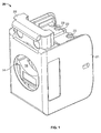
- a cap 20 which includes a cover 21 formed from Zamak or other metal or conductive material and preferably by a die-cast process.
- Cap 20 further includes a plastic lacing fixture 22 having a total of eight wire receiving spaces 23 to receive four pairs of wires.
- Cap 20 further includes a spring loaded wire clamp 25 which can move between an open position and a clamping position. In figure 1 , clamp 25 is shown in the clamping position.
- Cap includes an aperture 14 which receives a cable to be terminated.
- wire clamp 25 is shown in isolation and includes latches 18 which engage with recesses (not shown) inside cap to retain the latch in the free position or in the no wire inserted position.
- the lower surface 19 of clamp 25 includes recesses 17 which house compression springs 15. When installed in cover 21, springs 15 serve to bias the clamp 25 towards the clamping position.
- a cable is gripped by clamp 25 by being squeezed between the lower edge of recess 16 and the upper edge of recess 14 under force of compression springs 15. This type of cable clamp is also described in published paten specification WO2005/104300 , disclosing a connector according to the preamble of claim 1.
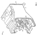
- Termination assembly 30 which includes a housing 31 also formed from Zamak or other metal or conductive material.
- Termination assembly 30 includes a number of wire receiving contacts in the form of insulation displacing contacts 32 which are mounted in pairs in contact carriers 33 which insulate them electrically from housing 31.
- the insulation displacing contacts are in electrical connection with connectors 40 or can be the same metal part (see fig 8 ) in housing 31 which form a part of a jack protected by dust cover 37 when used.
- Termination assembly further includes an upper cutting blade 34 and a lower cutting blade 74 mounted in housing 31 and each having a cutting portion in the form of cutting edges 35, 75 and a body portion being the remainder of each blade.
- Cap 20 and termination assembly 30 may be assembled together to form a connector which terminates a cable.
- the assembly of the connector will now be described. The following description explains termination of a four twisted pair foil shielded cable. However, other types of cable may be terminated by connectors according to the invention.
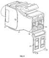
- each wire clamp in order to terminate a cable by way of the connector the wire clamp is pushed to the open position (as shown in figure 4 ) and the end of the cable 28 is inserted through apertures 14 and 16.
- the end of the cable is then prepared by removing a length of the outer insulation from the end of the cable and folding back the foil shield 12 to exposing the wires 24 inside the cable.
- Each of the wires 24 are then pushed into their correct positions in the wire receiving spaces 23 of lacing fixture 22 (see figure 1 and 3 ).
- Each wire receiving space includes a pair of guide slots 75 which are provided on opposite sides of each space 23 in pairs. The guide slots receive and guide the insulation displacing contacts during assembly of the connector.
- Latches 18 of wire clamp 25 are then released and compression springs 15 bias clamp 25 to the clamping position so that the folded back portion of the foil or braid shield 12 becomes gripped by cable clamp 25 to achieve electrical continuity between the foil or braid shield and cap 20.
- An internal shielding arrangement is provided inside cap 20 in the form of quadrant shield 29 (see figure 3 ) which is formed from Zamak or other conductive material and serves to shield wires in pairs in each quadrant from one another to reduce crosstalk and improve transmission performance.
- Recesses 26 receive the cutting edge 35 of cutting blade 34 when assembled as will be later described.
- Cap 20 is then assembled to the termination assembly 30.
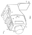
- the cap 20 and termination assembly 30 are shown partly assembled together. It can be seen that cutting portion 35 of blade 34 is about to cut free ends of wires 24 and as cap 20 and termination assembly 30 are brought closer together the free ends become severed and are ejected from the assembly by way of angled surface 38 and cutting portions 35 of blades 34 are accommodated by recess 26.
- only upper blade 34 is visible as lower blade 74 is obscured in the drawing. Blade 74 operates simultaneously with blade 34 to cut the oppositely directed group of wires which are also not visible in figure 5 .
- the guide slots 75 see fig 3
- cap 20 and termination assembly are fully assembled together to form connector 10.
- Latch 36 engages with aperture 27 to retain cap 20 and termination assembly 30 together.
- cover 21 overlaps with housing 31 in the region of rebate 39 (see fig 5 ). This overlap ensures that the wires inside the connector are completely shielded from the outside.
- cutting edge 35 is now hidden as it is accommodated by recess 26.
- Blade 34 overlaps with both cover 21 and housing 31 to shield the wires inside the connector.
- the assembled connector is shown in cross section. It can be seen that blade 34 overlaps with cover 21 and housing 31 to shield the inside of the connector. Similarly, lower blade 74 overlaps with cover 21 and housing 31 and also shields the inside of the connector. Further, it can be seen that the free ends of wires 24 have been pushed beyond blades 34, 74 during assembly. The free ends of wires 24 face into spaces 50 and 80 which avoid risk of electrical contact between wires 24 and housing 31.
- the wire receiving contacts were insulation displacing contacts which disrupt insulation about a wire to achieve electrical contact.
- the ends of the cable wires could be stripped prior to assembly and non-displacement type contacts could be utilised.
Claims (16)
- Steckverbinder (10) zum Anschließen eines Kommunikationskabels (28), der Folgendes einschließt:eine Anschlussbaugruppe (30), die eine Vielzahl von Drahtaufnahmekontakten (32) zum Aufnehmen von Drähten (24) eines Kabels (28) einschließt,eine Abbindevorrichtung (22) mit einer Anzahl von Drahtaufnahmeräumen (23) und die dafür verwendet wird, die Drähte (24) in einen Eingriff mit den Drahtaufnahmekontakten (32) zu führen,und eine Schneidklinge (34, 74), die einen Schneidabschnitt (35, 75) und einen Korpusabschnitt hat,wobei die Anschlussbaugruppe (30) und die Abbindevorrichtung (22) derart angeordnet sind, dass, wenn sie zusammengebaut werden, die Drähte (24), die in der Abbindevorrichtung (22) gehalten werden, an dem Schneidabschnitt (35, 75) der Klinge (34, 74) vorbei und in einen Eingriff mit den Drahtaufnahmekontakten (32) verschoben werden, wobei sich die Klinge (34, 74) quer zu den Drähten (24) erstreckt und sie überschüssigen Draht abschneidet,dadurch gekennzeichnet, dassder Korpusabschnitt der Klinge (34, 74) ausreichend vor den Drahtaufnahmekontakten (32) angeordnet ist, damit die abgeschnittenen Drähte (24), die mit den Kontakten (32) in Eingriff gebracht werden, weiter über den Körperabschnitt der Klinge (34, 74) hinaus verschoben werden.
- Steckverbinder (10) nach Anspruch 1, wobei die Klinge (34, 74) nach dem Zusammenbau dazu dient, die Drähte (24) innerhalb des Steckverbinders (10) gegenüber äußerer elektromagnetischer Strahlung abzuschirmen.
- Steckverbinder (10) nach Anspruch 1 oder Anspruch 2, der ferner eine Aussparung (26) in der Abbindevorrichtung (22) einschließt, die den Schneidabschnitt (35, 75) einer Schneidklinge (34, 74) aufnimmt, wenn der Steckverbinder (10) zusammengebaut wird.
- Steckverbinder (10) nach Anspruch 3, der ferner eine Oberfläche (38) einschließt, die in einem Winkel zu der Schneidklinge (34, 74) angeordnet ist, um das Ausstoßen von abgeschnittenen Drahtenden während des Zusammenbaus des Steckverbinders (10) zu unterstützen.
- Steckverbinder (10) nach einem der vorhergehenden Ansprüche, wobei der Steckverbinder (10) eine Klinke ist.
- Steckverbinder (10) nach einem der vorhergehenden Ansprüche, wobei die Drahtaufnahmekontakte (32) Schneidklemmkontakte sind.
- Steckverbinder (10) nach einem der vorhergehenden Ansprüche, wobei die Abbindevorrichtung (22) und die Anschlussbaugruppe (30) jeweils Metallkörper haben, die einander überlappen, wenn sie zusammengebaut sind.
- Steckverbinder (10) nach einem der vorhergehenden Ansprüche, der wenigstens zwei Schneidklingen (34, 74) einschließt.
- Steckverbinder (10) nach Anspruch 8, wobei die Klingen (34, 74) auf gegenüberliegenden Seiten des Steckverbinders (10) angeordnet sind.
- Steckverbinder (10) nach einem der vorhergehenden Ansprüche, der eine innere Abschirmungsanordnung einschließt, die eine Abschirmung zwischen Paaren von Drähten (24) gewährleistet.
- Steckverbinder (10) nach Anspruch 10, der dafür angeordnet ist, 1, 2 oder 4 Paare von Drähten (24) anzuschließen.
- Kappe (20) für einen Steckverbinder (10) nach einem der vorhergehenden Ansprüche, wobei die Kappe eine Abbindevorrichtung (22) und eine Aussparung (26), die den Schneidabschnitt (35, 75) der Schneidklinge (34, 74) aufnehmen kann, einschließt, wobei die Drahtaufnahmeräume (23) der Abbindevorrichtung (22) in einem ausreichenden Abstand zu der Aussparung (26) angeordnet sind, damit die abgeschnittenen Drähte (24), die mit den Kontakten (32) in Eingriff gebracht werden, weiter über den Körperabschnitt der Klinge (34, 74) hinaus verschoben werden.
- Kappe (20) nach Anspruch 12, die ferner eine Oberfläche (38) einschließt, die in einem Winkel angeordnet ist, um das Ausstoßen von abgeschnittenen Drahtenden zu unterstützen.
- Anschlussbaugruppe (30) zur Verwendung in einem Steckverbinder (10) nach einem der Ansprüche 1 bis 11, die Folgendes einschließt:die Vielzahl von Drahtaufnahmekontakten (32) zum Aufnehmen von Drähten (24) eines Kommunikationskabels (28),und die Schneidklinge (34, 74), die einen Schneidabschnitt (35, 75) und einen Korpusabschnitt hat,wobei die Anschlussbaugruppe (30) dafür angeordnet ist, mit der Abbindevorrichtung (22) derart zusammengebaut zu werden, dass, wenn sie zusammengebaut werden, die Drähte (24), die in der Abbindevorrichtung (22) gehalten werden, an dem Schneidabschnitt (35, 75) der Klinge vorbei und in einen Eingriff mit den Drahtaufnahmekontakten (32) verschoben werden, wobei sich die Klinge (34, 74) quer zu den Drähten (24) erstreckt und sie überschüssigen Draht abschneidet,dadurch gekennzeichnet, dassder Korpusabschnitt der Klinge (34, 74) ausreichend vor den Drahtaufnahmekontakten (32) angeordnet ist, damit die abgeschnittenen Drähte (24), die mit den Kontakten (32) in Eingriff gebracht werden, weiter über den Körperabschnitt der Klinge (34, 74) hinaus verschoben werden.
- Anschlussbaugruppe (30) nach Anspruch 14, die zwei Schneidklingen (34, 74) einschließt.
- Kombination aus einem Kabel (28) und einem Steckverbinder (10), wobei das Kabel (28) durch den Steckverbinder (10) nach einem der Ansprüche 1 bis 11 angeschlossen ist.
Priority Applications (1)
| Application Number | Priority Date | Filing Date | Title |
|---|---|---|---|
| PL07824432T PL2089937T3 (pl) | 2006-11-13 | 2007-11-02 | Złącze |
Applications Claiming Priority (2)
| Application Number | Priority Date | Filing Date | Title |
|---|---|---|---|
| GBGB0622461.2A GB0622461D0 (en) | 2006-11-13 | 2006-11-13 | A connector |
| PCT/GB2007/004193 WO2008059203A2 (en) | 2006-11-13 | 2007-11-02 | A connector |
Publications (2)
| Publication Number | Publication Date |
|---|---|
| EP2089937A2 EP2089937A2 (de) | 2009-08-19 |
| EP2089937B1 true EP2089937B1 (de) | 2012-03-14 |
Family
ID=37594710
Family Applications (1)
| Application Number | Title | Priority Date | Filing Date |
|---|---|---|---|
| EP07824432A Active EP2089937B1 (de) | 2006-11-13 | 2007-11-02 | Verbinder |
Country Status (14)
| Country | Link |
|---|---|
| US (1) | US7766688B2 (de) |
| EP (1) | EP2089937B1 (de) |
| CN (1) | CN101573842B (de) |
| AT (1) | ATE549772T1 (de) |
| AU (1) | AU2007320977B2 (de) |
| BR (1) | BRPI0718643A2 (de) |
| CA (1) | CA2669251C (de) |
| CO (1) | CO6180476A2 (de) |
| DK (1) | DK2089937T3 (de) |
| ES (1) | ES2386499T3 (de) |
| GB (1) | GB0622461D0 (de) |
| MX (1) | MX2009004629A (de) |
| PL (1) | PL2089937T3 (de) |
| WO (1) | WO2008059203A2 (de) |
Families Citing this family (24)
| Publication number | Priority date | Publication date | Assignee | Title |
|---|---|---|---|---|
| DE102009021594B4 (de) | 2009-04-09 | 2018-04-12 | Phoenix Contact Gmbh & Co. Kg | Elektrischer Steckverbinder und elektrische Steckverbindung sowie Verfahren zum Anschließen der Andern eines mehradrigen Kabels an einen elektrischen Steckverbinder |
| EP2256867B1 (de) * | 2009-05-11 | 2017-10-04 | CommScope Connectivity Spain, S.L. | Elektrische Verbindungsanordnung |
| US7871285B1 (en) * | 2009-12-22 | 2011-01-18 | Tyco Electronics Corporation | Methods and apparatus for terminating electrical connectors to cables |
| DE102010014615B4 (de) * | 2010-04-10 | 2012-08-09 | Tyco Electronics Nederland B.V. | Anschlussklemme mit Schneideinrichtung für eine elektrische Leitung |
| FR2977388B1 (fr) * | 2011-06-28 | 2013-07-12 | Amphenol Air Lb | Dispositif de blocage de faisceaux de conducteurs pour connecteur de raccordement |
| JP5259858B1 (ja) * | 2012-05-16 | 2013-08-07 | 株式会社東芝 | コネクタ、回路モジュールおよび電子機器 |
| US9343822B2 (en) | 2013-03-15 | 2016-05-17 | Leviton Manufacturing Co., Inc. | Communications connector system |
| USD751034S1 (en) * | 2013-09-30 | 2016-03-08 | Lem Intellectual Property Sa | Electrical current transducer |
| CN104577624B (zh) * | 2013-10-18 | 2017-06-23 | 泰科电子(上海)有限公司 | 端接装置、压接工具、工具组合和用于将导线端接至通信模块的方法 |
| US9627827B2 (en) | 2014-04-14 | 2017-04-18 | Leviton Manufacturing Co., Inc. | Communication outlet with shutter mechanism and wire manager |
| CN106415944A (zh) * | 2014-04-23 | 2017-02-15 | 泰科电子公司 | 具有屏蔽帽和屏蔽端子的电连接器 |
| USD752590S1 (en) * | 2014-06-19 | 2016-03-29 | Leviton Manufacturing Co., Ltd. | Communication outlet |
| ES2583636B1 (es) | 2015-03-20 | 2017-06-29 | Te Connectivity Amp España, S.L.U. | Conector con caja de enlace separable |
| ES2584540B1 (es) | 2015-03-27 | 2017-07-05 | Te Connectivity Amp España, S.L.U. | Pestillo para conector de telecomunicaciones |
| US9608379B1 (en) | 2015-10-14 | 2017-03-28 | Leviton Manufacturing Co., Inc. | Communication connector |
| MX2018004543A (es) * | 2015-10-14 | 2018-07-06 | Leviton Manufacturing Co | TERMINAL DE COMUNICACIíN CON MECANISMO OBTURADOR Y GESTOR DE ALAMBRES. |
| US10135207B2 (en) | 2016-01-31 | 2018-11-20 | Leviton Manufacturing Co., Inc. | High-speed data communications connector |
| WO2017201177A1 (en) | 2016-05-20 | 2017-11-23 | Communications Systems, Inc. | Toolless communications jack |
| WO2018009698A1 (en) | 2016-07-08 | 2018-01-11 | Commscope Technologies Llc | Connector assembly with grounding clamp system |
| AU2017312480B2 (en) | 2016-08-15 | 2022-05-19 | Commscope Technologies Llc | Connector assembly with grounding |
| US11356751B2 (en) | 2017-06-19 | 2022-06-07 | Commscope Technologies Llc | High density bezel for patch panel |
| EP3707915B1 (de) | 2017-11-10 | 2023-09-13 | Commscope Technologies LLC | Telekommunikationstafel mit erdungsdraht |
| EP3657604A1 (de) * | 2018-11-26 | 2020-05-27 | TE Connectivity Germany GmbH | Kabelanschlussanordnung mit elektrisch isolierenden schneidklingen |
| US11112034B2 (en) * | 2019-06-18 | 2021-09-07 | Globalmedia Group, Llc | Cable keeper |
Family Cites Families (4)
| Publication number | Priority date | Publication date | Assignee | Title |
|---|---|---|---|---|
| US4444447A (en) * | 1982-05-24 | 1984-04-24 | Minnesota Mining And Manufacturing Company | Electrical wire connector |
| JPH08162177A (ja) * | 1994-12-05 | 1996-06-21 | Yazaki Corp | 圧接コネクタへの電線圧接方法及び圧接コネクタ |
| DE60209094T2 (de) * | 2002-11-19 | 2006-09-14 | Tyco Electronics AMP Española S.A. | Vorrichtung und Verfahren zum Anschliessen von Kabeln |
| PL1738436T3 (pl) * | 2004-04-23 | 2012-03-30 | Tyco Electronics Amp Espana S A | Nakładka, zespół przyłączeniowy oraz zespół obudowy do modułowego wtyku połączenia telekomunikacyjnego |
-
2006
- 2006-11-13 GB GBGB0622461.2A patent/GB0622461D0/en not_active Ceased
-
2007
- 2007-11-02 WO PCT/GB2007/004193 patent/WO2008059203A2/en active Application Filing
- 2007-11-02 CA CA2669251A patent/CA2669251C/en not_active Expired - Fee Related
- 2007-11-02 AT AT07824432T patent/ATE549772T1/de active
- 2007-11-02 CN CN2007800420114A patent/CN101573842B/zh active Active
- 2007-11-02 BR BRPI0718643-6A patent/BRPI0718643A2/pt not_active IP Right Cessation
- 2007-11-02 MX MX2009004629A patent/MX2009004629A/es active IP Right Grant
- 2007-11-02 EP EP07824432A patent/EP2089937B1/de active Active
- 2007-11-02 DK DK07824432.4T patent/DK2089937T3/da active
- 2007-11-02 US US12/514,489 patent/US7766688B2/en active Active
- 2007-11-02 ES ES07824432T patent/ES2386499T3/es active Active
- 2007-11-02 AU AU2007320977A patent/AU2007320977B2/en active Active
- 2007-11-02 PL PL07824432T patent/PL2089937T3/pl unknown
-
2009
- 2009-05-11 CO CO09047487A patent/CO6180476A2/es active IP Right Grant
Also Published As
| Publication number | Publication date |
|---|---|
| DK2089937T3 (da) | 2012-07-02 |
| PL2089937T3 (pl) | 2012-08-31 |
| CO6180476A2 (es) | 2010-07-19 |
| ES2386499T3 (es) | 2012-08-22 |
| GB0622461D0 (en) | 2006-12-20 |
| ATE549772T1 (de) | 2012-03-15 |
| CA2669251C (en) | 2015-06-02 |
| WO2008059203A3 (en) | 2008-07-17 |
| AU2007320977A1 (en) | 2008-05-22 |
| BRPI0718643A2 (pt) | 2013-11-26 |
| CN101573842B (zh) | 2011-10-19 |
| CN101573842A (zh) | 2009-11-04 |
| EP2089937A2 (de) | 2009-08-19 |
| US7766688B2 (en) | 2010-08-03 |
| MX2009004629A (es) | 2009-06-30 |
| US20100029122A1 (en) | 2010-02-04 |
| WO2008059203A2 (en) | 2008-05-22 |
| CA2669251A1 (en) | 2008-05-22 |
| AU2007320977B2 (en) | 2011-03-31 |
Similar Documents
| Publication | Publication Date | Title |
|---|---|---|
| EP2089937B1 (de) | Verbinder | |
| EP1050932B1 (de) | Eine abgeschirmte Anschlussklemme und ein Verfahren für die Verbindung einer abgeschirmten Anschlussklemme | |
| EP2517304B1 (de) | Elektrischer steckverbinder | |
| JP4823286B2 (ja) | ケーブルの末端に装着して用いるモジュラ・プラグ | |
| EP1295363B1 (de) | Verbinder für hohe übertragungsgeschwindigkeit | |
| CN109314352B (zh) | 端子模块及连接器 | |
| EP2497164B1 (de) | Modularer steckverbinder für hochgeschwindigkeitsanwendungen | |
| EP2256867B1 (de) | Elektrische Verbindungsanordnung | |
| WO2007113307A1 (en) | Retention ferrule for cable connector | |
| MX2015000529A (es) | Conector de cables. | |
| JP2013524435A (ja) | 電気コネクタ用ケーブルオーガナイザー | |
| US6080018A (en) | Grounding arrangement for a shielded cable connector | |
| JPH07106003A (ja) | モジュラー式同軸ケーブルコネクター及びそのアッセンブリ方法 | |
| US6238246B1 (en) | Grounding bracket for a shielded cable connector | |
| KR20010021451A (ko) | 고속 케이블의 차폐체를 연결하는 수단을 포함한 전기커넥터 | |
| KR20240049371A (ko) | 고속, 견고한 커넥터 | |
| US20230062139A1 (en) | High speed, ruggedized connector | |
| AU2010247553B2 (en) | Electrical connector | |
| EP2011193A1 (de) | Retentionshülse für einen kabelverbinder |
Legal Events
| Date | Code | Title | Description |
|---|---|---|---|
| PUAI | Public reference made under article 153(3) epc to a published international application that has entered the european phase |
Free format text: ORIGINAL CODE: 0009012 |
|
| 17P | Request for examination filed |
Effective date: 20090511 |
|
| AK | Designated contracting states |
Kind code of ref document: A2 Designated state(s): AT BE BG CH CY CZ DE DK EE ES FI FR GB GR HU IE IS IT LI LT LU LV MC MT NL PL PT RO SE SI SK TR |
|
| 17Q | First examination report despatched |
Effective date: 20090820 |
|
| DAX | Request for extension of the european patent (deleted) | ||
| GRAP | Despatch of communication of intention to grant a patent |
Free format text: ORIGINAL CODE: EPIDOSNIGR1 |
|
| GRAS | Grant fee paid |
Free format text: ORIGINAL CODE: EPIDOSNIGR3 |
|
| GRAA | (expected) grant |
Free format text: ORIGINAL CODE: 0009210 |
|
| AK | Designated contracting states |
Kind code of ref document: B1 Designated state(s): AT BE BG CH CY CZ DE DK EE ES FI FR GB GR HU IE IS IT LI LT LU LV MC MT NL PL PT RO SE SI SK TR |
|
| REG | Reference to a national code |
Ref country code: GB Ref legal event code: FG4D |
|
| REG | Reference to a national code |
Ref country code: AT Ref legal event code: REF Ref document number: 549772 Country of ref document: AT Kind code of ref document: T Effective date: 20120315 Ref country code: CH Ref legal event code: EP |
|
| REG | Reference to a national code |
Ref country code: IE Ref legal event code: FG4D |
|
| REG | Reference to a national code |
Ref country code: DE Ref legal event code: R096 Ref document number: 602007021352 Country of ref document: DE Effective date: 20120510 |
|
| REG | Reference to a national code |
Ref country code: NL Ref legal event code: T3 |
|
| REG | Reference to a national code |
Ref country code: DK Ref legal event code: T3 |
|
| REG | Reference to a national code |
Ref country code: SE Ref legal event code: TRGR |
|
| PG25 | Lapsed in a contracting state [announced via postgrant information from national office to epo] |
Ref country code: LT Free format text: LAPSE BECAUSE OF FAILURE TO SUBMIT A TRANSLATION OF THE DESCRIPTION OR TO PAY THE FEE WITHIN THE PRESCRIBED TIME-LIMIT Effective date: 20120314 |
|
| REG | Reference to a national code |
Ref country code: ES Ref legal event code: FG2A Ref document number: 2386499 Country of ref document: ES Kind code of ref document: T3 Effective date: 20120822 |
|
| LTIE | Lt: invalidation of european patent or patent extension |
Effective date: 20120314 |
|
| PG25 | Lapsed in a contracting state [announced via postgrant information from national office to epo] |
Ref country code: GR Free format text: LAPSE BECAUSE OF FAILURE TO SUBMIT A TRANSLATION OF THE DESCRIPTION OR TO PAY THE FEE WITHIN THE PRESCRIBED TIME-LIMIT Effective date: 20120615 Ref country code: FI Free format text: LAPSE BECAUSE OF FAILURE TO SUBMIT A TRANSLATION OF THE DESCRIPTION OR TO PAY THE FEE WITHIN THE PRESCRIBED TIME-LIMIT Effective date: 20120314 Ref country code: LV Free format text: LAPSE BECAUSE OF FAILURE TO SUBMIT A TRANSLATION OF THE DESCRIPTION OR TO PAY THE FEE WITHIN THE PRESCRIBED TIME-LIMIT Effective date: 20120314 |
|
| REG | Reference to a national code |
Ref country code: PL Ref legal event code: T3 |
|
| REG | Reference to a national code |
Ref country code: AT Ref legal event code: MK05 Ref document number: 549772 Country of ref document: AT Kind code of ref document: T Effective date: 20120314 |
|
| PG25 | Lapsed in a contracting state [announced via postgrant information from national office to epo] |
Ref country code: CY Free format text: LAPSE BECAUSE OF FAILURE TO SUBMIT A TRANSLATION OF THE DESCRIPTION OR TO PAY THE FEE WITHIN THE PRESCRIBED TIME-LIMIT Effective date: 20120314 |
|
| PG25 | Lapsed in a contracting state [announced via postgrant information from national office to epo] |
Ref country code: SI Free format text: LAPSE BECAUSE OF FAILURE TO SUBMIT A TRANSLATION OF THE DESCRIPTION OR TO PAY THE FEE WITHIN THE PRESCRIBED TIME-LIMIT Effective date: 20120314 Ref country code: CZ Free format text: LAPSE BECAUSE OF FAILURE TO SUBMIT A TRANSLATION OF THE DESCRIPTION OR TO PAY THE FEE WITHIN THE PRESCRIBED TIME-LIMIT Effective date: 20120314 Ref country code: IS Free format text: LAPSE BECAUSE OF FAILURE TO SUBMIT A TRANSLATION OF THE DESCRIPTION OR TO PAY THE FEE WITHIN THE PRESCRIBED TIME-LIMIT Effective date: 20120714 Ref country code: EE Free format text: LAPSE BECAUSE OF FAILURE TO SUBMIT A TRANSLATION OF THE DESCRIPTION OR TO PAY THE FEE WITHIN THE PRESCRIBED TIME-LIMIT Effective date: 20120314 Ref country code: RO Free format text: LAPSE BECAUSE OF FAILURE TO SUBMIT A TRANSLATION OF THE DESCRIPTION OR TO PAY THE FEE WITHIN THE PRESCRIBED TIME-LIMIT Effective date: 20120314 |
|
| PG25 | Lapsed in a contracting state [announced via postgrant information from national office to epo] |
Ref country code: PT Free format text: LAPSE BECAUSE OF FAILURE TO SUBMIT A TRANSLATION OF THE DESCRIPTION OR TO PAY THE FEE WITHIN THE PRESCRIBED TIME-LIMIT Effective date: 20120716 Ref country code: SK Free format text: LAPSE BECAUSE OF FAILURE TO SUBMIT A TRANSLATION OF THE DESCRIPTION OR TO PAY THE FEE WITHIN THE PRESCRIBED TIME-LIMIT Effective date: 20120314 |
|
| PLBE | No opposition filed within time limit |
Free format text: ORIGINAL CODE: 0009261 |
|
| STAA | Information on the status of an ep patent application or granted ep patent |
Free format text: STATUS: NO OPPOSITION FILED WITHIN TIME LIMIT |
|
| PG25 | Lapsed in a contracting state [announced via postgrant information from national office to epo] |
Ref country code: AT Free format text: LAPSE BECAUSE OF FAILURE TO SUBMIT A TRANSLATION OF THE DESCRIPTION OR TO PAY THE FEE WITHIN THE PRESCRIBED TIME-LIMIT Effective date: 20120314 |
|
| 26N | No opposition filed |
Effective date: 20121217 |
|
| REG | Reference to a national code |
Ref country code: DE Ref legal event code: R097 Ref document number: 602007021352 Country of ref document: DE Effective date: 20121217 |
|
| REG | Reference to a national code |
Ref country code: CH Ref legal event code: PL |
|
| PG25 | Lapsed in a contracting state [announced via postgrant information from national office to epo] |
Ref country code: LI Free format text: LAPSE BECAUSE OF NON-PAYMENT OF DUE FEES Effective date: 20121130 Ref country code: CH Free format text: LAPSE BECAUSE OF NON-PAYMENT OF DUE FEES Effective date: 20121130 Ref country code: BG Free format text: LAPSE BECAUSE OF FAILURE TO SUBMIT A TRANSLATION OF THE DESCRIPTION OR TO PAY THE FEE WITHIN THE PRESCRIBED TIME-LIMIT Effective date: 20120614 |
|
| REG | Reference to a national code |
Ref country code: IE Ref legal event code: MM4A |
|
| PG25 | Lapsed in a contracting state [announced via postgrant information from national office to epo] |
Ref country code: IE Free format text: LAPSE BECAUSE OF NON-PAYMENT OF DUE FEES Effective date: 20121102 |
|
| PG25 | Lapsed in a contracting state [announced via postgrant information from national office to epo] |
Ref country code: MT Free format text: LAPSE BECAUSE OF FAILURE TO SUBMIT A TRANSLATION OF THE DESCRIPTION OR TO PAY THE FEE WITHIN THE PRESCRIBED TIME-LIMIT Effective date: 20120314 |
|
| PG25 | Lapsed in a contracting state [announced via postgrant information from national office to epo] |
Ref country code: TR Free format text: LAPSE BECAUSE OF FAILURE TO SUBMIT A TRANSLATION OF THE DESCRIPTION OR TO PAY THE FEE WITHIN THE PRESCRIBED TIME-LIMIT Effective date: 20120314 Ref country code: MC Free format text: LAPSE BECAUSE OF NON-PAYMENT OF DUE FEES Effective date: 20121130 |
|
| PG25 | Lapsed in a contracting state [announced via postgrant information from national office to epo] |
Ref country code: LU Free format text: LAPSE BECAUSE OF NON-PAYMENT OF DUE FEES Effective date: 20121102 |
|
| PG25 | Lapsed in a contracting state [announced via postgrant information from national office to epo] |
Ref country code: HU Free format text: LAPSE BECAUSE OF FAILURE TO SUBMIT A TRANSLATION OF THE DESCRIPTION OR TO PAY THE FEE WITHIN THE PRESCRIBED TIME-LIMIT Effective date: 20071102 |
|
| REG | Reference to a national code |
Ref country code: FR Ref legal event code: PLFP Year of fee payment: 9 |
|
| REG | Reference to a national code |
Ref country code: FR Ref legal event code: PLFP Year of fee payment: 10 |
|
| PGFP | Annual fee paid to national office [announced via postgrant information from national office to epo] |
Ref country code: DK Payment date: 20161123 Year of fee payment: 10 Ref country code: NL Payment date: 20161126 Year of fee payment: 10 |
|
| PGFP | Annual fee paid to national office [announced via postgrant information from national office to epo] |
Ref country code: SE Payment date: 20161125 Year of fee payment: 10 |
|
| REG | Reference to a national code |
Ref country code: FR Ref legal event code: PLFP Year of fee payment: 11 |
|
| REG | Reference to a national code |
Ref country code: DK Ref legal event code: EBP Effective date: 20171130 |
|
| REG | Reference to a national code |
Ref country code: SE Ref legal event code: EUG |
|
| REG | Reference to a national code |
Ref country code: NL Ref legal event code: MM Effective date: 20171201 |
|
| PG25 | Lapsed in a contracting state [announced via postgrant information from national office to epo] |
Ref country code: SE Free format text: LAPSE BECAUSE OF NON-PAYMENT OF DUE FEES Effective date: 20171103 |
|
| PG25 | Lapsed in a contracting state [announced via postgrant information from national office to epo] |
Ref country code: NL Free format text: LAPSE BECAUSE OF NON-PAYMENT OF DUE FEES Effective date: 20171201 |
|
| PG25 | Lapsed in a contracting state [announced via postgrant information from national office to epo] |
Ref country code: DK Free format text: LAPSE BECAUSE OF NON-PAYMENT OF DUE FEES Effective date: 20171130 |
|
| PGFP | Annual fee paid to national office [announced via postgrant information from national office to epo] |
Ref country code: IT Payment date: 20221123 Year of fee payment: 16 Ref country code: FR Payment date: 20221123 Year of fee payment: 16 Ref country code: ES Payment date: 20221201 Year of fee payment: 16 Ref country code: DE Payment date: 20221125 Year of fee payment: 16 |
|
| PGFP | Annual fee paid to national office [announced via postgrant information from national office to epo] |
Ref country code: PL Payment date: 20221020 Year of fee payment: 16 Ref country code: BE Payment date: 20221128 Year of fee payment: 16 |
|
| PGFP | Annual fee paid to national office [announced via postgrant information from national office to epo] |
Ref country code: GB Payment date: 20231127 Year of fee payment: 17 |