EP2089937B1 - A connector - Google Patents
A connector Download PDFInfo
- Publication number
- EP2089937B1 EP2089937B1 EP07824432A EP07824432A EP2089937B1 EP 2089937 B1 EP2089937 B1 EP 2089937B1 EP 07824432 A EP07824432 A EP 07824432A EP 07824432 A EP07824432 A EP 07824432A EP 2089937 B1 EP2089937 B1 EP 2089937B1
- Authority
- EP
- European Patent Office
- Prior art keywords
- connector
- wires
- blade
- contacts
- cutting
- Prior art date
- Legal status (The legal status is an assumption and is not a legal conclusion. Google has not performed a legal analysis and makes no representation as to the accuracy of the status listed.)
- Active
Links
- 238000009413 insulation Methods 0.000 claims description 9
- 239000002184 metal Substances 0.000 claims description 3
- 230000005670 electromagnetic radiation Effects 0.000 claims description 2
- 239000011888 foil Substances 0.000 description 4
- 229910000842 Zamak Inorganic materials 0.000 description 3
- 230000006835 compression Effects 0.000 description 3
- 238000007906 compression Methods 0.000 description 3
- 239000004020 conductor Substances 0.000 description 3
- 239000000428 dust Substances 0.000 description 2
- 239000007769 metal material Substances 0.000 description 2
- 238000007792 addition Methods 0.000 description 1
- 230000004075 alteration Effects 0.000 description 1
- 230000005540 biological transmission Effects 0.000 description 1
- 239000000969 carrier Substances 0.000 description 1
- 238000006073 displacement reaction Methods 0.000 description 1
- 238000002955 isolation Methods 0.000 description 1
- 238000000034 method Methods 0.000 description 1
Images


Classifications
-
- H—ELECTRICITY
- H01—ELECTRIC ELEMENTS
- H01R—ELECTRICALLY-CONDUCTIVE CONNECTIONS; STRUCTURAL ASSOCIATIONS OF A PLURALITY OF MUTUALLY-INSULATED ELECTRICAL CONNECTING ELEMENTS; COUPLING DEVICES; CURRENT COLLECTORS
- H01R4/00—Electrically-conductive connections between two or more conductive members in direct contact, i.e. touching one another; Means for effecting or maintaining such contact; Electrically-conductive connections having two or more spaced connecting locations for conductors and using contact members penetrating insulation
- H01R4/24—Connections using contact members penetrating or cutting insulation or cable strands
- H01R4/2416—Connections using contact members penetrating or cutting insulation or cable strands the contact members having insulation-cutting edges, e.g. of tuning fork type
- H01R4/242—Connections using contact members penetrating or cutting insulation or cable strands the contact members having insulation-cutting edges, e.g. of tuning fork type the contact members being plates having a single slot
- H01R4/2425—Flat plates, e.g. multi-layered flat plates
- H01R4/2429—Flat plates, e.g. multi-layered flat plates mounted in an insulating base
- H01R4/2433—Flat plates, e.g. multi-layered flat plates mounted in an insulating base one part of the base being movable to push the cable into the slot
-
- H—ELECTRICITY
- H01—ELECTRIC ELEMENTS
- H01R—ELECTRICALLY-CONDUCTIVE CONNECTIONS; STRUCTURAL ASSOCIATIONS OF A PLURALITY OF MUTUALLY-INSULATED ELECTRICAL CONNECTING ELEMENTS; COUPLING DEVICES; CURRENT COLLECTORS
- H01R13/00—Details of coupling devices of the kinds covered by groups H01R12/70 or H01R24/00 - H01R33/00
- H01R13/46—Bases; Cases
- H01R13/465—Identification means, e.g. labels, tags, markings
-
- H—ELECTRICITY
- H01—ELECTRIC ELEMENTS
- H01R—ELECTRICALLY-CONDUCTIVE CONNECTIONS; STRUCTURAL ASSOCIATIONS OF A PLURALITY OF MUTUALLY-INSULATED ELECTRICAL CONNECTING ELEMENTS; COUPLING DEVICES; CURRENT COLLECTORS
- H01R13/00—Details of coupling devices of the kinds covered by groups H01R12/70 or H01R24/00 - H01R33/00
- H01R13/46—Bases; Cases
- H01R13/50—Bases; Cases formed as an integral body
- H01R13/501—Bases; Cases formed as an integral body comprising an integral hinge or a frangible part
-
- H—ELECTRICITY
- H01—ELECTRIC ELEMENTS
- H01R—ELECTRICALLY-CONDUCTIVE CONNECTIONS; STRUCTURAL ASSOCIATIONS OF A PLURALITY OF MUTUALLY-INSULATED ELECTRICAL CONNECTING ELEMENTS; COUPLING DEVICES; CURRENT COLLECTORS
- H01R13/00—Details of coupling devices of the kinds covered by groups H01R12/70 or H01R24/00 - H01R33/00
- H01R13/58—Means for relieving strain on wire connection, e.g. cord grip, for avoiding loosening of connections between wires and terminals within a coupling device terminating a cable
- H01R13/5804—Means for relieving strain on wire connection, e.g. cord grip, for avoiding loosening of connections between wires and terminals within a coupling device terminating a cable comprising a separate cable clamping part
- H01R13/5812—Means for relieving strain on wire connection, e.g. cord grip, for avoiding loosening of connections between wires and terminals within a coupling device terminating a cable comprising a separate cable clamping part the cable clamping being achieved by mounting the separate part on the housing of the coupling device
-
- H—ELECTRICITY
- H01—ELECTRIC ELEMENTS
- H01R—ELECTRICALLY-CONDUCTIVE CONNECTIONS; STRUCTURAL ASSOCIATIONS OF A PLURALITY OF MUTUALLY-INSULATED ELECTRICAL CONNECTING ELEMENTS; COUPLING DEVICES; CURRENT COLLECTORS
- H01R13/00—Details of coupling devices of the kinds covered by groups H01R12/70 or H01R24/00 - H01R33/00
- H01R13/62—Means for facilitating engagement or disengagement of coupling parts or for holding them in engagement
- H01R13/627—Snap or like fastening
- H01R13/6271—Latching means integral with the housing
- H01R13/6272—Latching means integral with the housing comprising a single latching arm
-
- H—ELECTRICITY
- H01—ELECTRIC ELEMENTS
- H01R—ELECTRICALLY-CONDUCTIVE CONNECTIONS; STRUCTURAL ASSOCIATIONS OF A PLURALITY OF MUTUALLY-INSULATED ELECTRICAL CONNECTING ELEMENTS; COUPLING DEVICES; CURRENT COLLECTORS
- H01R13/00—Details of coupling devices of the kinds covered by groups H01R12/70 or H01R24/00 - H01R33/00
- H01R13/648—Protective earth or shield arrangements on coupling devices, e.g. anti-static shielding
- H01R13/658—High frequency shielding arrangements, e.g. against EMI [Electro-Magnetic Interference] or EMP [Electro-Magnetic Pulse]
- H01R13/6581—Shield structure
- H01R13/6585—Shielding material individually surrounding or interposed between mutually spaced contacts
- H01R13/6589—Shielding material individually surrounding or interposed between mutually spaced contacts with wires separated by conductive housing parts
-
- H—ELECTRICITY
- H01—ELECTRIC ELEMENTS
- H01R—ELECTRICALLY-CONDUCTIVE CONNECTIONS; STRUCTURAL ASSOCIATIONS OF A PLURALITY OF MUTUALLY-INSULATED ELECTRICAL CONNECTING ELEMENTS; COUPLING DEVICES; CURRENT COLLECTORS
- H01R4/00—Electrically-conductive connections between two or more conductive members in direct contact, i.e. touching one another; Means for effecting or maintaining such contact; Electrically-conductive connections having two or more spaced connecting locations for conductors and using contact members penetrating insulation
- H01R4/24—Connections using contact members penetrating or cutting insulation or cable strands
- H01R4/2416—Connections using contact members penetrating or cutting insulation or cable strands the contact members having insulation-cutting edges, e.g. of tuning fork type
- H01R4/2445—Connections using contact members penetrating or cutting insulation or cable strands the contact members having insulation-cutting edges, e.g. of tuning fork type the contact members having additional means acting on the insulation or the wire, e.g. additional insulation penetrating means, strain relief means or wire cutting knives
Definitions
- This invention relates to a connector suitable for a telecommunications cable having a plurality of insulated wires.
- the present invention provides a connector according to claim 1.
- the blade may serve to shield the wires inside the connector from external electromagnetic radiation.
- the connector may further include a recess in the lacing fixture which receives the cutting portion of a cutting blade when the connector is assembled.
- the connector may further include a surface which is disposed at an angle to the cutting blade to assist in ejection of cut wire ends during the assembly of the connector.
- the connector may be a jack.
- the wire receiving contacts may be insulation displacing contacts.
- the lacing fixture and termination assembly may each have metal bodies which overlap one another when assembled together.
- the connector may include two cutting blades.
- the blades may be disposed on opposite sides of the connector.
- the connector may include an internal shielding arrangement which provides shielding between pairs of wires.
- the connector may be arranged to terminate 1, 2 or 4 pairs of wires.
- the present invention provides a cap according to claim 12.
- the cap may include a surface which is disposed at an angle to assist in ejection of cut wire ends.
- the present invention provides a termination assembly according to claim 14.
- the termination assembly may include at least two cutting blades.
- the present invention provides a combination according to claim 16.
- a cap 20 which includes a cover 21 formed from Zamak or other metal or conductive material and preferably by a die-cast process.
- Cap 20 further includes a plastic lacing fixture 22 having a total of eight wire receiving spaces 23 to receive four pairs of wires.
- Cap 20 further includes a spring loaded wire clamp 25 which can move between an open position and a clamping position. In figure 1 , clamp 25 is shown in the clamping position.
- Cap includes an aperture 14 which receives a cable to be terminated.
- wire clamp 25 is shown in isolation and includes latches 18 which engage with recesses (not shown) inside cap to retain the latch in the free position or in the no wire inserted position.
- the lower surface 19 of clamp 25 includes recesses 17 which house compression springs 15. When installed in cover 21, springs 15 serve to bias the clamp 25 towards the clamping position.
- a cable is gripped by clamp 25 by being squeezed between the lower edge of recess 16 and the upper edge of recess 14 under force of compression springs 15. This type of cable clamp is also described in published paten specification WO2005/104300 , disclosing a connector according to the preamble of claim 1.
- Termination assembly 30 which includes a housing 31 also formed from Zamak or other metal or conductive material.
- Termination assembly 30 includes a number of wire receiving contacts in the form of insulation displacing contacts 32 which are mounted in pairs in contact carriers 33 which insulate them electrically from housing 31.
- the insulation displacing contacts are in electrical connection with connectors 40 or can be the same metal part (see fig 8 ) in housing 31 which form a part of a jack protected by dust cover 37 when used.
- Termination assembly further includes an upper cutting blade 34 and a lower cutting blade 74 mounted in housing 31 and each having a cutting portion in the form of cutting edges 35, 75 and a body portion being the remainder of each blade.
- Cap 20 and termination assembly 30 may be assembled together to form a connector which terminates a cable.
- the assembly of the connector will now be described. The following description explains termination of a four twisted pair foil shielded cable. However, other types of cable may be terminated by connectors according to the invention.
- each wire clamp in order to terminate a cable by way of the connector the wire clamp is pushed to the open position (as shown in figure 4 ) and the end of the cable 28 is inserted through apertures 14 and 16.
- the end of the cable is then prepared by removing a length of the outer insulation from the end of the cable and folding back the foil shield 12 to exposing the wires 24 inside the cable.
- Each of the wires 24 are then pushed into their correct positions in the wire receiving spaces 23 of lacing fixture 22 (see figure 1 and 3 ).
- Each wire receiving space includes a pair of guide slots 75 which are provided on opposite sides of each space 23 in pairs. The guide slots receive and guide the insulation displacing contacts during assembly of the connector.
- Latches 18 of wire clamp 25 are then released and compression springs 15 bias clamp 25 to the clamping position so that the folded back portion of the foil or braid shield 12 becomes gripped by cable clamp 25 to achieve electrical continuity between the foil or braid shield and cap 20.
- An internal shielding arrangement is provided inside cap 20 in the form of quadrant shield 29 (see figure 3 ) which is formed from Zamak or other conductive material and serves to shield wires in pairs in each quadrant from one another to reduce crosstalk and improve transmission performance.
- Recesses 26 receive the cutting edge 35 of cutting blade 34 when assembled as will be later described.
- Cap 20 is then assembled to the termination assembly 30.
- the cap 20 and termination assembly 30 are shown partly assembled together. It can be seen that cutting portion 35 of blade 34 is about to cut free ends of wires 24 and as cap 20 and termination assembly 30 are brought closer together the free ends become severed and are ejected from the assembly by way of angled surface 38 and cutting portions 35 of blades 34 are accommodated by recess 26.
- only upper blade 34 is visible as lower blade 74 is obscured in the drawing. Blade 74 operates simultaneously with blade 34 to cut the oppositely directed group of wires which are also not visible in figure 5 .
- the guide slots 75 see fig 3
- cap 20 and termination assembly are fully assembled together to form connector 10.
- Latch 36 engages with aperture 27 to retain cap 20 and termination assembly 30 together.
- cover 21 overlaps with housing 31 in the region of rebate 39 (see fig 5 ). This overlap ensures that the wires inside the connector are completely shielded from the outside.
- cutting edge 35 is now hidden as it is accommodated by recess 26.
- Blade 34 overlaps with both cover 21 and housing 31 to shield the wires inside the connector.
- the assembled connector is shown in cross section. It can be seen that blade 34 overlaps with cover 21 and housing 31 to shield the inside of the connector. Similarly, lower blade 74 overlaps with cover 21 and housing 31 and also shields the inside of the connector. Further, it can be seen that the free ends of wires 24 have been pushed beyond blades 34, 74 during assembly. The free ends of wires 24 face into spaces 50 and 80 which avoid risk of electrical contact between wires 24 and housing 31.
- the wire receiving contacts were insulation displacing contacts which disrupt insulation about a wire to achieve electrical contact.
- the ends of the cable wires could be stripped prior to assembly and non-displacement type contacts could be utilised.
Abstract
Description
- This invention relates to a connector suitable for a telecommunications cable having a plurality of insulated wires.
- In a first aspect the present invention provides a connector according to claim 1.
- After assembly the blade may serve to shield the wires inside the connector from external electromagnetic radiation.
- The connector may further include a recess in the lacing fixture which receives the cutting portion of a cutting blade when the connector is assembled.
- The connector may further include a surface which is disposed at an angle to the cutting blade to assist in ejection of cut wire ends during the assembly of the connector. The connector may be a jack.
- The wire receiving contacts may be insulation displacing contacts.
- The lacing fixture and termination assembly may each have metal bodies which overlap one another when assembled together.
- The connector may include two cutting blades. The blades may be disposed on opposite sides of the connector.
- The connector may include an internal shielding arrangement which provides shielding between pairs of wires.
- The connector may be arranged to terminate 1, 2 or 4 pairs of wires.
- In a second aspect the present invention provides a cap according to
claim 12. - The cap may include a surface which is disposed at an angle to assist in ejection of cut wire ends.
- In a third aspect the present invention provides a termination assembly according to
claim 14. - The termination assembly may include at least two cutting blades.
- In a fourth aspect the present invention provides a combination according to
claim 16. - An embodiment of the present invention will now be described, by way of example only, with reference to the accompanying drawings, in which:
-
Figure 1 is a perspective rear view of an embodiment of a cap for a connector according to the present invention; -
Figure 1A is a perspective view of the cable clamp offigure 1 ; -
Figure 1B is an alternative perspective view of the cable clamp offigure 1 ; -
Figure 2 is a perspective view of a housing for use with the cap offigure 1 ; -
Figure 3 is a perspective front view of the cap offigure 1 showing wires of a cable in the wire receiving spaces; -
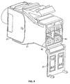
Figure 4 is a perspective rear view of the cap offigure 1 showing wires of a cable. -
Figure 5 is a perspective view of the cap and housing offigures 1 and2 partially assembled together to form a connector; and -
Figure 6 is a perspective view of a fully assembled connector formed from the cap and housing offigures 1 and2 shown with dust cover open; -
Figure 7 is a detail view of the connector offigure 6 ; -
Figure 8 is an alternative perspective view of the connector offigure 6 ; and -
Figure 9 is a side cross sectional view of the connector offigure 6 . - Referring to
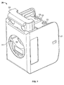
figure 1 acap 20 is shown which includes acover 21 formed from Zamak or other metal or conductive material and preferably by a die-cast process.Cap 20 further includes aplastic lacing fixture 22 having a total of eightwire receiving spaces 23 to receive four pairs of wires.Cap 20 further includes a spring loadedwire clamp 25 which can move between an open position and a clamping position. Infigure 1 ,clamp 25 is shown in the clamping position. Cap includes anaperture 14 which receives a cable to be terminated. - Referring to
figure 1A ,wire clamp 25 is shown in isolation and includeslatches 18 which engage with recesses (not shown) inside cap to retain the latch in the free position or in the no wire inserted position. Referring tofigure 1B , thelower surface 19 ofclamp 25 includesrecesses 17 which house compression springs 15. When installed incover 21,springs 15 serve to bias theclamp 25 towards the clamping position. A cable is gripped byclamp 25 by being squeezed between the lower edge ofrecess 16 and the upper edge ofrecess 14 under force ofcompression springs 15. This type of cable clamp is also described in published paten specificationWO2005/104300 , disclosing a connector according to the preamble of claim 1. - Referring to
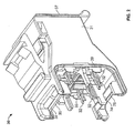
figure 2 , atermination assembly 30 is shown which includes ahousing 31 also formed from Zamak or other metal or conductive material.Termination assembly 30 includes a number of wire receiving contacts in the form ofinsulation displacing contacts 32 which are mounted in pairs incontact carriers 33 which insulate them electrically fromhousing 31. The insulation displacing contacts are in electrical connection withconnectors 40 or can be the same metal part (seefig 8 ) inhousing 31 which form a part of a jack protected bydust cover 37 when used. Termination assembly further includes anupper cutting blade 34 and alower cutting blade 74 mounted inhousing 31 and each having a cutting portion in the form ofcutting edges -
Cap 20 andtermination assembly 30 may be assembled together to form a connector which terminates a cable. The assembly of the connector will now be described. The following description explains termination of a four twisted pair foil shielded cable. However, other types of cable may be terminated by connectors according to the invention. - Referring to
figures 1 ,3 and4 , in order to terminate a cable by way of the connector the wire clamp is pushed to the open position (as shown infigure 4 ) and the end of thecable 28 is inserted throughapertures foil shield 12 to exposing thewires 24 inside the cable. Each of thewires 24 are then pushed into their correct positions in thewire receiving spaces 23 of lacing fixture 22 (seefigure 1 and3 ). Each wire receiving space includes a pair ofguide slots 75 which are provided on opposite sides of eachspace 23 in pairs. The guide slots receive and guide the insulation displacing contacts during assembly of the connector. -
Latches 18 ofwire clamp 25 are then released andcompression springs 15bias clamp 25 to the clamping position so that the folded back portion of the foil orbraid shield 12 becomes gripped bycable clamp 25 to achieve electrical continuity between the foil or braid shield andcap 20. - An internal shielding arrangement is provided inside
cap 20 in the form of quadrant shield 29 (seefigure 3 ) which is formed from Zamak or other conductive material and serves to shield wires in pairs in each quadrant from one another to reduce crosstalk and improve transmission performance.Recesses 26 receive thecutting edge 35 ofcutting blade 34 when assembled as will be later described. -
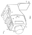
Cap 20 is then assembled to thetermination assembly 30. Referring tofigure 5 , thecap 20 andtermination assembly 30 are shown partly assembled together. It can be seen that cuttingportion 35 ofblade 34 is about to cut free ends ofwires 24 and ascap 20 andtermination assembly 30 are brought closer together the free ends become severed and are ejected from the assembly by way ofangled surface 38 and cuttingportions 35 ofblades 34 are accommodated byrecess 26. Infigure 5 , onlyupper blade 34 is visible aslower blade 74 is obscured in the drawing. Blade 74 operates simultaneously withblade 34 to cut the oppositely directed group of wires which are also not visible infigure 5 . Ascap 21 andhousing 31 are pushed together the guide slots 75 (seefig 3 ) receive theinsulation displacing contacts 32 and guide them into proper engagement with each ofwires 24. - Referring to
figure 6 ,cap 20 and termination assembly are fully assembled together to formconnector 10.Latch 36 engages withaperture 27 to retaincap 20 andtermination assembly 30 together. When assembled, cover 21 overlaps withhousing 31 in the region of rebate 39 (seefig 5 ). This overlap ensures that the wires inside the connector are completely shielded from the outside. - Referring to
figure 7 , it can be seen that cuttingedge 35 is now hidden as it is accommodated byrecess 26.Blade 34 overlaps with both cover 21 andhousing 31 to shield the wires inside the connector. - Referring to
figure 9 , the assembled connector is shown in cross section. It can be seen thatblade 34 overlaps withcover 21 andhousing 31 to shield the inside of the connector. Similarly,lower blade 74 overlaps withcover 21 andhousing 31 and also shields the inside of the connector. Further, it can be seen that the free ends ofwires 24 have been pushed beyondblades wires 24 face intospaces wires 24 andhousing 31. - In the above described embodiment the wire receiving contacts were insulation displacing contacts which disrupt insulation about a wire to achieve electrical contact. Similarly, the ends of the cable wires could be stripped prior to assembly and non-displacement type contacts could be utilised.
- Any reference to prior art contained herein is not to be taken as an admission that the information is common general knowledge, unless otherwise indicated.
- Finally, it is to be appreciated that various alterations or additions may be made to the parts previously described without departing from the scope of the claims.
Claims (16)
- A connector (10) for terminating a communications cable (28) including:a termination assembly (30) including a plurality of wire receiving contacts (32) for receiving wires (24) of a cable (28);a lacing fixture (22) with a number of wire receiving spaces (23) and which is used to guide the wires (24) into engagement with the wire receiving contacts (32);and a cutting blade (34, 74) having a cutting portion (35, 75) and a body portion;wherein the termination assembly (30) and lacing fixture (22) are arranged such that, as they are assembled together, wires (24) held in the lacing fixture (22) are displaced past the cutting portion (35, 75) of the blade (34, 74) and into engagement with the wire receiving contacts (32), which blade (34, 74) extends transversely to the wires (24) and which cuts off excess wire,characterised in thatthe body portion of the blade (34, 74) is located sufficiently in advance of the wire receiving contacts (32) for the cut wires (24) engaged with the contacts (32) to be further displaced beyond the body portion of the blade (34, 74).
- A connector (10) according to claim 1 wherein after assembly the blade (34, 74) serves to shield the wires (24) inside the connector (10) from external electromagnetic radiation.
- A connector (10) according to either claim 1 or claim 2 which further includes a recess (26) in the lacing fixture (22) which receives the cutting portion (35, 75) of a cutting blade (34, 74) when the connector (10) is assembled.
- A connector (10) according to claim 3 which further includes a surface (38) which is disposed at an angle to the cutting blade (34, 74) to assist in ejection of cut wire ends during the assembly of the connector (10).
- A connector (10) according to any preceding claim wherein the connector (10) is a jack.
- A connector (10) according to any preceding claim wherein the wire receiving contacts (32) are insulation displacing contacts.
- A connector (10) according to any preceding claim wherein the lacing fixture (22) and termination assembly (30) each have metal bodies which overlap one another when assembled together.
- A connector (10) according to any preceding claim which includes at least two cutting blades (34, 74).
- A connector (10) according to claim 8 wherein the blades (34, 74) are disposed on opposite sides of the connector (10).
- A connector (10) according to any preceding claim which includes an internal shielding arrangement which provides shielding between pairs of wires (24).
- A connector (10) according to claim 10 which is arranged to terminate 1, 2 or 4 pairs of wires (24).
- A cap (20) for a connector (10) as claimed in any one of the preceding claims which cap includes the lacing fixture (22) and a recess (26) which can accommodate the cutting portion (35, 75) of the cutting blade (34, 74), wherein the wire receiving spaces (23) of the lacing fixture (22) are sufficiently arranged at a distance to the recess (26) for the cut wires (24) engaged with the contacts (32) to be further displaced beyond the body portion of the blade (34, 74).
- A cap (20) according to claim 12 further including a surface (38) which is disposed at an angle to assist in ejection of cut wire ends.
- A termination assembly (30) for use in a connector (10) according to any of claims 1 to 11, including
the said plurality of wire receiving contacts (32) for receiving wires (24) of a communications cable (28),
and the said cutting blade (34, 74) having a cutting portion (35, 75) and a body portion,
wherein the termination assembly (30) is arranged to be assembled with the said lacing fixture (22) such that, as they are assembled together, wires (24) held in the lacing fixture (22) are displaced past the cutting portion (35, 75) of the blade
and into engagement with the wire receiving contacts (32), which blade (34, 74) extends transversely to the wires (24) and which cuts off excess wire,
characterised in that
the body portion of the blade (34, 74) is located sufficiently in advance of the wire-receiving contacts (32) for the cut wires (24) engaged with the contacts (32) to be further displaced beyond the body portion of the blade (34, 74). - A termination assembly (30) according to claim 14 which includes two cutting blades (34, 74).
- A combination of a cable (28) and a connector (10), the cable (28) being terminated by the connector (10) as defined in any one of claims 1 to 11.
Priority Applications (1)
| Application Number | Priority Date | Filing Date | Title |
|---|---|---|---|
| PL07824432T PL2089937T3 (en) | 2006-11-13 | 2007-11-02 | A connector |
Applications Claiming Priority (2)
| Application Number | Priority Date | Filing Date | Title |
|---|---|---|---|
| GBGB0622461.2A GB0622461D0 (en) | 2006-11-13 | 2006-11-13 | A connector |
| PCT/GB2007/004193 WO2008059203A2 (en) | 2006-11-13 | 2007-11-02 | A connector |
Publications (2)
| Publication Number | Publication Date |
|---|---|
| EP2089937A2 EP2089937A2 (en) | 2009-08-19 |
| EP2089937B1 true EP2089937B1 (en) | 2012-03-14 |
Family
ID=37594710
Family Applications (1)
| Application Number | Title | Priority Date | Filing Date |
|---|---|---|---|
| EP07824432A Active EP2089937B1 (en) | 2006-11-13 | 2007-11-02 | A connector |
Country Status (14)
| Country | Link |
|---|---|
| US (1) | US7766688B2 (en) |
| EP (1) | EP2089937B1 (en) |
| CN (1) | CN101573842B (en) |
| AT (1) | ATE549772T1 (en) |
| AU (1) | AU2007320977B2 (en) |
| BR (1) | BRPI0718643A2 (en) |
| CA (1) | CA2669251C (en) |
| CO (1) | CO6180476A2 (en) |
| DK (1) | DK2089937T3 (en) |
| ES (1) | ES2386499T3 (en) |
| GB (1) | GB0622461D0 (en) |
| MX (1) | MX2009004629A (en) |
| PL (1) | PL2089937T3 (en) |
| WO (1) | WO2008059203A2 (en) |
Families Citing this family (24)
| Publication number | Priority date | Publication date | Assignee | Title |
|---|---|---|---|---|
| DE102009021594B4 (en) | 2009-04-09 | 2018-04-12 | Phoenix Contact Gmbh & Co. Kg | Electrical connector and electrical connector and method for connecting the remainder of a multicore cable to an electrical connector |
| EP2256867B1 (en) | 2009-05-11 | 2017-10-04 | CommScope Connectivity Spain, S.L. | Electrical Connector |
| US7871285B1 (en) * | 2009-12-22 | 2011-01-18 | Tyco Electronics Corporation | Methods and apparatus for terminating electrical connectors to cables |
| DE102010014615B4 (en) * | 2010-04-10 | 2012-08-09 | Tyco Electronics Nederland B.V. | Connection terminal with cutting device for an electric cable |
| FR2977388B1 (en) * | 2011-06-28 | 2013-07-12 | Amphenol Air Lb | DEVICE FOR LOCKING CONDUCTOR BEAMS FOR CONNECTOR CONNECTOR |
| JP5259858B1 (en) * | 2012-05-16 | 2013-08-07 | 株式会社東芝 | Connectors, circuit modules and electronic equipment |
| US9343822B2 (en) | 2013-03-15 | 2016-05-17 | Leviton Manufacturing Co., Inc. | Communications connector system |
| USD751034S1 (en) * | 2013-09-30 | 2016-03-08 | Lem Intellectual Property Sa | Electrical current transducer |
| CN104577624B (en) * | 2013-10-18 | 2017-06-23 | 泰科电子(上海)有限公司 | Terminating set, crimping tool, tool combinations and for by the method for conductor termination to communication module |
| US9627827B2 (en) | 2014-04-14 | 2017-04-18 | Leviton Manufacturing Co., Inc. | Communication outlet with shutter mechanism and wire manager |
| EP3134945B1 (en) * | 2014-04-23 | 2019-06-12 | TE Connectivity Corporation | Electrical connector with shield cap and shielded terminals |
| USD752590S1 (en) | 2014-06-19 | 2016-03-29 | Leviton Manufacturing Co., Ltd. | Communication outlet |
| ES2583636B1 (en) | 2015-03-20 | 2017-06-29 | Te Connectivity Amp España, S.L.U. | Connector with detachable link box |
| ES2584540B1 (en) | 2015-03-27 | 2017-07-05 | Te Connectivity Amp España, S.L.U. | Latch for telecommunications connector |
| EP3363082B1 (en) * | 2015-10-14 | 2021-09-22 | Leviton Manufacturing Company, Inc. | Communication outlet with shutter mechanism and wire manager |
| US9608379B1 (en) | 2015-10-14 | 2017-03-28 | Leviton Manufacturing Co., Inc. | Communication connector |
| US10135207B2 (en) | 2016-01-31 | 2018-11-20 | Leviton Manufacturing Co., Inc. | High-speed data communications connector |
| WO2017201177A1 (en) | 2016-05-20 | 2017-11-23 | Communications Systems, Inc. | Toolless communications jack |
| WO2018009698A1 (en) | 2016-07-08 | 2018-01-11 | Commscope Technologies Llc | Connector assembly with grounding clamp system |
| CN109565132B (en) * | 2016-08-15 | 2021-06-18 | 康普技术有限责任公司 | Connector assembly with grounding part |
| CN116207543A (en) | 2017-06-19 | 2023-06-02 | 康普技术有限责任公司 | High-density frame for connector panel |
| CN111345046B (en) | 2017-11-10 | 2022-10-11 | 康普技术有限责任公司 | Telecommunication board with grounding wire |
| EP3657604A1 (en) * | 2018-11-26 | 2020-05-27 | TE Connectivity Germany GmbH | Cable terminating assembly with electrically insulating cutting blades |
| US11112034B2 (en) * | 2019-06-18 | 2021-09-07 | Globalmedia Group, Llc | Cable keeper |
Family Cites Families (4)
| Publication number | Priority date | Publication date | Assignee | Title |
|---|---|---|---|---|
| US4444447A (en) * | 1982-05-24 | 1984-04-24 | Minnesota Mining And Manufacturing Company | Electrical wire connector |
| JPH08162177A (en) * | 1994-12-05 | 1996-06-21 | Yazaki Corp | Pressure contact method of wire to pressure contact connector and pressure contact connector |
| ATE317599T1 (en) * | 2002-11-19 | 2006-02-15 | Tyco Electronics Amp Espanola | APPARATUS AND METHOD FOR CONNECTING CABLES |
| WO2005104300A1 (en) * | 2004-04-23 | 2005-11-03 | Tyco Electronics Amp Espana Sa | A cap, a termination assembly and a housing assembly for a modular telecom connection jack |
-
2006
- 2006-11-13 GB GBGB0622461.2A patent/GB0622461D0/en not_active Ceased
-
2007
- 2007-11-02 WO PCT/GB2007/004193 patent/WO2008059203A2/en active Application Filing
- 2007-11-02 AT AT07824432T patent/ATE549772T1/en active
- 2007-11-02 CA CA2669251A patent/CA2669251C/en not_active Expired - Fee Related
- 2007-11-02 MX MX2009004629A patent/MX2009004629A/en active IP Right Grant
- 2007-11-02 ES ES07824432T patent/ES2386499T3/en active Active
- 2007-11-02 DK DK07824432.4T patent/DK2089937T3/en active
- 2007-11-02 PL PL07824432T patent/PL2089937T3/en unknown
- 2007-11-02 US US12/514,489 patent/US7766688B2/en active Active
- 2007-11-02 AU AU2007320977A patent/AU2007320977B2/en active Active
- 2007-11-02 BR BRPI0718643-6A patent/BRPI0718643A2/en not_active IP Right Cessation
- 2007-11-02 EP EP07824432A patent/EP2089937B1/en active Active
- 2007-11-02 CN CN2007800420114A patent/CN101573842B/en active Active
-
2009
- 2009-05-11 CO CO09047487A patent/CO6180476A2/en active IP Right Grant
Also Published As
| Publication number | Publication date |
|---|---|
| GB0622461D0 (en) | 2006-12-20 |
| AU2007320977A1 (en) | 2008-05-22 |
| WO2008059203A2 (en) | 2008-05-22 |
| AU2007320977B2 (en) | 2011-03-31 |
| CN101573842B (en) | 2011-10-19 |
| MX2009004629A (en) | 2009-06-30 |
| CN101573842A (en) | 2009-11-04 |
| DK2089937T3 (en) | 2012-07-02 |
| ES2386499T3 (en) | 2012-08-22 |
| WO2008059203A3 (en) | 2008-07-17 |
| US20100029122A1 (en) | 2010-02-04 |
| CA2669251A1 (en) | 2008-05-22 |
| CO6180476A2 (en) | 2010-07-19 |
| ATE549772T1 (en) | 2012-03-15 |
| BRPI0718643A2 (en) | 2013-11-26 |
| US7766688B2 (en) | 2010-08-03 |
| PL2089937T3 (en) | 2012-08-31 |
| CA2669251C (en) | 2015-06-02 |
| EP2089937A2 (en) | 2009-08-19 |
Similar Documents
| Publication | Publication Date | Title |
|---|---|---|
| EP2089937B1 (en) | A connector | |
| EP1050932B1 (en) | A shielding terminal and method for connecting a shielding terminal | |
| EP2517304B1 (en) | Electrical connector | |
| JP4823286B2 (en) | Modular plug for use at the end of the cable | |
| EP1295363B1 (en) | High speed connector | |
| CN109314352B (en) | Terminal module and connector | |
| EP2497164B1 (en) | Modular connector plug for high speed applications | |
| EP2256867B1 (en) | Electrical Connector | |
| WO2007113307A1 (en) | Retention ferrule for cable connector | |
| MX2015000529A (en) | Wire connector. | |
| JP2013524435A (en) | Cable organizer for electrical connectors | |
| US6080018A (en) | Grounding arrangement for a shielded cable connector | |
| JPH07106003A (en) | Modular type coaxial cable connector and assembling method thereof | |
| US6238246B1 (en) | Grounding bracket for a shielded cable connector | |
| KR20010021451A (en) | Electrical Connector Including Means for Terminating the Shield of a High Speed Cable | |
| KR20240049371A (en) | High-speed, robust connector | |
| US20230062139A1 (en) | High speed, ruggedized connector | |
| AU2010247553B2 (en) | Electrical connector | |
| EP2011193A1 (en) | Retention ferrule for cable connector |
Legal Events
| Date | Code | Title | Description |
|---|---|---|---|
| PUAI | Public reference made under article 153(3) epc to a published international application that has entered the european phase |
Free format text: ORIGINAL CODE: 0009012 |
|
| 17P | Request for examination filed |
Effective date: 20090511 |
|
| AK | Designated contracting states |
Kind code of ref document: A2 Designated state(s): AT BE BG CH CY CZ DE DK EE ES FI FR GB GR HU IE IS IT LI LT LU LV MC MT NL PL PT RO SE SI SK TR |
|
| 17Q | First examination report despatched |
Effective date: 20090820 |
|
| DAX | Request for extension of the european patent (deleted) | ||
| GRAP | Despatch of communication of intention to grant a patent |
Free format text: ORIGINAL CODE: EPIDOSNIGR1 |
|
| GRAS | Grant fee paid |
Free format text: ORIGINAL CODE: EPIDOSNIGR3 |
|
| GRAA | (expected) grant |
Free format text: ORIGINAL CODE: 0009210 |
|
| AK | Designated contracting states |
Kind code of ref document: B1 Designated state(s): AT BE BG CH CY CZ DE DK EE ES FI FR GB GR HU IE IS IT LI LT LU LV MC MT NL PL PT RO SE SI SK TR |
|
| REG | Reference to a national code |
Ref country code: GB Ref legal event code: FG4D |
|
| REG | Reference to a national code |
Ref country code: AT Ref legal event code: REF Ref document number: 549772 Country of ref document: AT Kind code of ref document: T Effective date: 20120315 Ref country code: CH Ref legal event code: EP |
|
| REG | Reference to a national code |
Ref country code: IE Ref legal event code: FG4D |
|
| REG | Reference to a national code |
Ref country code: DE Ref legal event code: R096 Ref document number: 602007021352 Country of ref document: DE Effective date: 20120510 |
|
| REG | Reference to a national code |
Ref country code: NL Ref legal event code: T3 |
|
| REG | Reference to a national code |
Ref country code: DK Ref legal event code: T3 |
|
| REG | Reference to a national code |
Ref country code: SE Ref legal event code: TRGR |
|
| PG25 | Lapsed in a contracting state [announced via postgrant information from national office to epo] |
Ref country code: LT Free format text: LAPSE BECAUSE OF FAILURE TO SUBMIT A TRANSLATION OF THE DESCRIPTION OR TO PAY THE FEE WITHIN THE PRESCRIBED TIME-LIMIT Effective date: 20120314 |
|
| REG | Reference to a national code |
Ref country code: ES Ref legal event code: FG2A Ref document number: 2386499 Country of ref document: ES Kind code of ref document: T3 Effective date: 20120822 |
|
| LTIE | Lt: invalidation of european patent or patent extension |
Effective date: 20120314 |
|
| PG25 | Lapsed in a contracting state [announced via postgrant information from national office to epo] |
Ref country code: GR Free format text: LAPSE BECAUSE OF FAILURE TO SUBMIT A TRANSLATION OF THE DESCRIPTION OR TO PAY THE FEE WITHIN THE PRESCRIBED TIME-LIMIT Effective date: 20120615 Ref country code: FI Free format text: LAPSE BECAUSE OF FAILURE TO SUBMIT A TRANSLATION OF THE DESCRIPTION OR TO PAY THE FEE WITHIN THE PRESCRIBED TIME-LIMIT Effective date: 20120314 Ref country code: LV Free format text: LAPSE BECAUSE OF FAILURE TO SUBMIT A TRANSLATION OF THE DESCRIPTION OR TO PAY THE FEE WITHIN THE PRESCRIBED TIME-LIMIT Effective date: 20120314 |
|
| REG | Reference to a national code |
Ref country code: PL Ref legal event code: T3 |
|
| REG | Reference to a national code |
Ref country code: AT Ref legal event code: MK05 Ref document number: 549772 Country of ref document: AT Kind code of ref document: T Effective date: 20120314 |
|
| PG25 | Lapsed in a contracting state [announced via postgrant information from national office to epo] |
Ref country code: CY Free format text: LAPSE BECAUSE OF FAILURE TO SUBMIT A TRANSLATION OF THE DESCRIPTION OR TO PAY THE FEE WITHIN THE PRESCRIBED TIME-LIMIT Effective date: 20120314 |
|
| PG25 | Lapsed in a contracting state [announced via postgrant information from national office to epo] |
Ref country code: SI Free format text: LAPSE BECAUSE OF FAILURE TO SUBMIT A TRANSLATION OF THE DESCRIPTION OR TO PAY THE FEE WITHIN THE PRESCRIBED TIME-LIMIT Effective date: 20120314 Ref country code: CZ Free format text: LAPSE BECAUSE OF FAILURE TO SUBMIT A TRANSLATION OF THE DESCRIPTION OR TO PAY THE FEE WITHIN THE PRESCRIBED TIME-LIMIT Effective date: 20120314 Ref country code: IS Free format text: LAPSE BECAUSE OF FAILURE TO SUBMIT A TRANSLATION OF THE DESCRIPTION OR TO PAY THE FEE WITHIN THE PRESCRIBED TIME-LIMIT Effective date: 20120714 Ref country code: EE Free format text: LAPSE BECAUSE OF FAILURE TO SUBMIT A TRANSLATION OF THE DESCRIPTION OR TO PAY THE FEE WITHIN THE PRESCRIBED TIME-LIMIT Effective date: 20120314 Ref country code: RO Free format text: LAPSE BECAUSE OF FAILURE TO SUBMIT A TRANSLATION OF THE DESCRIPTION OR TO PAY THE FEE WITHIN THE PRESCRIBED TIME-LIMIT Effective date: 20120314 |
|
| PG25 | Lapsed in a contracting state [announced via postgrant information from national office to epo] |
Ref country code: PT Free format text: LAPSE BECAUSE OF FAILURE TO SUBMIT A TRANSLATION OF THE DESCRIPTION OR TO PAY THE FEE WITHIN THE PRESCRIBED TIME-LIMIT Effective date: 20120716 Ref country code: SK Free format text: LAPSE BECAUSE OF FAILURE TO SUBMIT A TRANSLATION OF THE DESCRIPTION OR TO PAY THE FEE WITHIN THE PRESCRIBED TIME-LIMIT Effective date: 20120314 |
|
| PLBE | No opposition filed within time limit |
Free format text: ORIGINAL CODE: 0009261 |
|
| STAA | Information on the status of an ep patent application or granted ep patent |
Free format text: STATUS: NO OPPOSITION FILED WITHIN TIME LIMIT |
|
| PG25 | Lapsed in a contracting state [announced via postgrant information from national office to epo] |
Ref country code: AT Free format text: LAPSE BECAUSE OF FAILURE TO SUBMIT A TRANSLATION OF THE DESCRIPTION OR TO PAY THE FEE WITHIN THE PRESCRIBED TIME-LIMIT Effective date: 20120314 |
|
| 26N | No opposition filed |
Effective date: 20121217 |
|
| REG | Reference to a national code |
Ref country code: DE Ref legal event code: R097 Ref document number: 602007021352 Country of ref document: DE Effective date: 20121217 |
|
| REG | Reference to a national code |
Ref country code: CH Ref legal event code: PL |
|
| PG25 | Lapsed in a contracting state [announced via postgrant information from national office to epo] |
Ref country code: LI Free format text: LAPSE BECAUSE OF NON-PAYMENT OF DUE FEES Effective date: 20121130 Ref country code: CH Free format text: LAPSE BECAUSE OF NON-PAYMENT OF DUE FEES Effective date: 20121130 Ref country code: BG Free format text: LAPSE BECAUSE OF FAILURE TO SUBMIT A TRANSLATION OF THE DESCRIPTION OR TO PAY THE FEE WITHIN THE PRESCRIBED TIME-LIMIT Effective date: 20120614 |
|
| REG | Reference to a national code |
Ref country code: IE Ref legal event code: MM4A |
|
| PG25 | Lapsed in a contracting state [announced via postgrant information from national office to epo] |
Ref country code: IE Free format text: LAPSE BECAUSE OF NON-PAYMENT OF DUE FEES Effective date: 20121102 |
|
| PG25 | Lapsed in a contracting state [announced via postgrant information from national office to epo] |
Ref country code: MT Free format text: LAPSE BECAUSE OF FAILURE TO SUBMIT A TRANSLATION OF THE DESCRIPTION OR TO PAY THE FEE WITHIN THE PRESCRIBED TIME-LIMIT Effective date: 20120314 |
|
| PG25 | Lapsed in a contracting state [announced via postgrant information from national office to epo] |
Ref country code: TR Free format text: LAPSE BECAUSE OF FAILURE TO SUBMIT A TRANSLATION OF THE DESCRIPTION OR TO PAY THE FEE WITHIN THE PRESCRIBED TIME-LIMIT Effective date: 20120314 Ref country code: MC Free format text: LAPSE BECAUSE OF NON-PAYMENT OF DUE FEES Effective date: 20121130 |
|
| PG25 | Lapsed in a contracting state [announced via postgrant information from national office to epo] |
Ref country code: LU Free format text: LAPSE BECAUSE OF NON-PAYMENT OF DUE FEES Effective date: 20121102 |
|
| PG25 | Lapsed in a contracting state [announced via postgrant information from national office to epo] |
Ref country code: HU Free format text: LAPSE BECAUSE OF FAILURE TO SUBMIT A TRANSLATION OF THE DESCRIPTION OR TO PAY THE FEE WITHIN THE PRESCRIBED TIME-LIMIT Effective date: 20071102 |
|
| REG | Reference to a national code |
Ref country code: FR Ref legal event code: PLFP Year of fee payment: 9 |
|
| REG | Reference to a national code |
Ref country code: FR Ref legal event code: PLFP Year of fee payment: 10 |
|
| PGFP | Annual fee paid to national office [announced via postgrant information from national office to epo] |
Ref country code: DK Payment date: 20161123 Year of fee payment: 10 Ref country code: NL Payment date: 20161126 Year of fee payment: 10 |
|
| PGFP | Annual fee paid to national office [announced via postgrant information from national office to epo] |
Ref country code: SE Payment date: 20161125 Year of fee payment: 10 |
|
| REG | Reference to a national code |
Ref country code: FR Ref legal event code: PLFP Year of fee payment: 11 |
|
| REG | Reference to a national code |
Ref country code: DK Ref legal event code: EBP Effective date: 20171130 |
|
| REG | Reference to a national code |
Ref country code: SE Ref legal event code: EUG |
|
| REG | Reference to a national code |
Ref country code: NL Ref legal event code: MM Effective date: 20171201 |
|
| PG25 | Lapsed in a contracting state [announced via postgrant information from national office to epo] |
Ref country code: SE Free format text: LAPSE BECAUSE OF NON-PAYMENT OF DUE FEES Effective date: 20171103 |
|
| PG25 | Lapsed in a contracting state [announced via postgrant information from national office to epo] |
Ref country code: NL Free format text: LAPSE BECAUSE OF NON-PAYMENT OF DUE FEES Effective date: 20171201 |
|
| PG25 | Lapsed in a contracting state [announced via postgrant information from national office to epo] |
Ref country code: DK Free format text: LAPSE BECAUSE OF NON-PAYMENT OF DUE FEES Effective date: 20171130 |
|
| PGFP | Annual fee paid to national office [announced via postgrant information from national office to epo] |
Ref country code: IT Payment date: 20221123 Year of fee payment: 16 Ref country code: FR Payment date: 20221123 Year of fee payment: 16 Ref country code: ES Payment date: 20221201 Year of fee payment: 16 Ref country code: DE Payment date: 20221125 Year of fee payment: 16 |
|
| PGFP | Annual fee paid to national office [announced via postgrant information from national office to epo] |
Ref country code: PL Payment date: 20221020 Year of fee payment: 16 Ref country code: BE Payment date: 20221128 Year of fee payment: 16 |
|
| PGFP | Annual fee paid to national office [announced via postgrant information from national office to epo] |
Ref country code: GB Payment date: 20231127 Year of fee payment: 17 |