EP2087221B1 - Wärmetauscher, insbesondere für ein kraftfahrzeug - Google Patents
Wärmetauscher, insbesondere für ein kraftfahrzeug Download PDFInfo
- Publication number
- EP2087221B1 EP2087221B1 EP07846531.7A EP07846531A EP2087221B1 EP 2087221 B1 EP2087221 B1 EP 2087221B1 EP 07846531 A EP07846531 A EP 07846531A EP 2087221 B1 EP2087221 B1 EP 2087221B1
- Authority
- EP
- European Patent Office
- Prior art keywords
- heat exchanger
- exchanger according
- housing
- fluid
- control element
- Prior art date
- Legal status (The legal status is an assumption and is not a legal conclusion. Google has not performed a legal analysis and makes no representation as to the accuracy of the status listed.)
- Not-in-force
Links
- 239000012530 fluid Substances 0.000 claims description 14
- 239000002826 coolant Substances 0.000 claims description 11
- 230000015572 biosynthetic process Effects 0.000 claims description 10
- 238000002485 combustion reaction Methods 0.000 claims description 8
- 238000001816 cooling Methods 0.000 claims description 4
- 230000000930 thermomechanical effect Effects 0.000 claims description 4
- 239000000463 material Substances 0.000 claims description 3
- 238000007789 sealing Methods 0.000 claims description 2
- 238000010586 diagram Methods 0.000 claims 1
- 239000007789 gas Substances 0.000 description 11
- 238000000465 moulding Methods 0.000 description 8
- 238000002347 injection Methods 0.000 description 3
- 239000007924 injection Substances 0.000 description 3
- 230000007246 mechanism Effects 0.000 description 2
- 238000013021 overheating Methods 0.000 description 2
- 230000009467 reduction Effects 0.000 description 2
- 238000007493 shaping process Methods 0.000 description 2
- 230000008859 change Effects 0.000 description 1
- 238000010276 construction Methods 0.000 description 1
- 230000001419 dependent effect Effects 0.000 description 1
- 239000003344 environmental pollutant Substances 0.000 description 1
- 230000006870 function Effects 0.000 description 1
- 238000004519 manufacturing process Methods 0.000 description 1
- 229910052751 metal Inorganic materials 0.000 description 1
- 239000002184 metal Substances 0.000 description 1
- 150000002739 metals Chemical class 0.000 description 1
- 239000012778 molding material Substances 0.000 description 1
- 238000005457 optimization Methods 0.000 description 1
- 231100000719 pollutant Toxicity 0.000 description 1
- 239000000565 sealant Substances 0.000 description 1
- 229910001220 stainless steel Inorganic materials 0.000 description 1
- 239000010935 stainless steel Substances 0.000 description 1
- XLYOFNOQVPJJNP-UHFFFAOYSA-N water Substances O XLYOFNOQVPJJNP-UHFFFAOYSA-N 0.000 description 1
Images
Classifications
-
- F—MECHANICAL ENGINEERING; LIGHTING; HEATING; WEAPONS; BLASTING
- F28—HEAT EXCHANGE IN GENERAL
- F28D—HEAT-EXCHANGE APPARATUS, NOT PROVIDED FOR IN ANOTHER SUBCLASS, IN WHICH THE HEAT-EXCHANGE MEDIA DO NOT COME INTO DIRECT CONTACT
- F28D7/00—Heat-exchange apparatus having stationary tubular conduit assemblies for both heat-exchange media, the media being in contact with different sides of a conduit wall
- F28D7/16—Heat-exchange apparatus having stationary tubular conduit assemblies for both heat-exchange media, the media being in contact with different sides of a conduit wall the conduits being arranged in parallel spaced relation
- F28D7/1684—Heat-exchange apparatus having stationary tubular conduit assemblies for both heat-exchange media, the media being in contact with different sides of a conduit wall the conduits being arranged in parallel spaced relation the conduits having a non-circular cross-section
-
- F—MECHANICAL ENGINEERING; LIGHTING; HEATING; WEAPONS; BLASTING
- F02—COMBUSTION ENGINES; HOT-GAS OR COMBUSTION-PRODUCT ENGINE PLANTS
- F02M—SUPPLYING COMBUSTION ENGINES IN GENERAL WITH COMBUSTIBLE MIXTURES OR CONSTITUENTS THEREOF
- F02M26/00—Engine-pertinent apparatus for adding exhaust gases to combustion-air, main fuel or fuel-air mixture, e.g. by exhaust gas recirculation [EGR] systems
- F02M26/13—Arrangement or layout of EGR passages, e.g. in relation to specific engine parts or for incorporation of accessories
- F02M26/22—Arrangement or layout of EGR passages, e.g. in relation to specific engine parts or for incorporation of accessories with coolers in the recirculation passage
-
- F—MECHANICAL ENGINEERING; LIGHTING; HEATING; WEAPONS; BLASTING
- F02—COMBUSTION ENGINES; HOT-GAS OR COMBUSTION-PRODUCT ENGINE PLANTS
- F02M—SUPPLYING COMBUSTION ENGINES IN GENERAL WITH COMBUSTIBLE MIXTURES OR CONSTITUENTS THEREOF
- F02M26/00—Engine-pertinent apparatus for adding exhaust gases to combustion-air, main fuel or fuel-air mixture, e.g. by exhaust gas recirculation [EGR] systems
- F02M26/13—Arrangement or layout of EGR passages, e.g. in relation to specific engine parts or for incorporation of accessories
- F02M26/22—Arrangement or layout of EGR passages, e.g. in relation to specific engine parts or for incorporation of accessories with coolers in the recirculation passage
- F02M26/29—Constructional details of the coolers, e.g. pipes, plates, ribs, insulation or materials
- F02M26/30—Connections of coolers to other devices, e.g. to valves, heaters, compressors or filters; Coolers characterised by their location on the engine
-
- F—MECHANICAL ENGINEERING; LIGHTING; HEATING; WEAPONS; BLASTING
- F02—COMBUSTION ENGINES; HOT-GAS OR COMBUSTION-PRODUCT ENGINE PLANTS
- F02M—SUPPLYING COMBUSTION ENGINES IN GENERAL WITH COMBUSTIBLE MIXTURES OR CONSTITUENTS THEREOF
- F02M26/00—Engine-pertinent apparatus for adding exhaust gases to combustion-air, main fuel or fuel-air mixture, e.g. by exhaust gas recirculation [EGR] systems
- F02M26/13—Arrangement or layout of EGR passages, e.g. in relation to specific engine parts or for incorporation of accessories
- F02M26/22—Arrangement or layout of EGR passages, e.g. in relation to specific engine parts or for incorporation of accessories with coolers in the recirculation passage
- F02M26/29—Constructional details of the coolers, e.g. pipes, plates, ribs, insulation or materials
- F02M26/32—Liquid-cooled heat exchangers
-
- F—MECHANICAL ENGINEERING; LIGHTING; HEATING; WEAPONS; BLASTING
- F02—COMBUSTION ENGINES; HOT-GAS OR COMBUSTION-PRODUCT ENGINE PLANTS
- F02M—SUPPLYING COMBUSTION ENGINES IN GENERAL WITH COMBUSTIBLE MIXTURES OR CONSTITUENTS THEREOF
- F02M26/00—Engine-pertinent apparatus for adding exhaust gases to combustion-air, main fuel or fuel-air mixture, e.g. by exhaust gas recirculation [EGR] systems
- F02M26/13—Arrangement or layout of EGR passages, e.g. in relation to specific engine parts or for incorporation of accessories
- F02M26/22—Arrangement or layout of EGR passages, e.g. in relation to specific engine parts or for incorporation of accessories with coolers in the recirculation passage
- F02M26/33—Arrangement or layout of EGR passages, e.g. in relation to specific engine parts or for incorporation of accessories with coolers in the recirculation passage controlling the temperature of the recirculated gases
-
- F—MECHANICAL ENGINEERING; LIGHTING; HEATING; WEAPONS; BLASTING
- F28—HEAT EXCHANGE IN GENERAL
- F28F—DETAILS OF HEAT-EXCHANGE AND HEAT-TRANSFER APPARATUS, OF GENERAL APPLICATION
- F28F21/00—Constructions of heat-exchange apparatus characterised by the selection of particular materials
- F28F21/06—Constructions of heat-exchange apparatus characterised by the selection of particular materials of plastics material
- F28F21/067—Details
-
- F—MECHANICAL ENGINEERING; LIGHTING; HEATING; WEAPONS; BLASTING
- F28—HEAT EXCHANGE IN GENERAL
- F28F—DETAILS OF HEAT-EXCHANGE AND HEAT-TRANSFER APPARATUS, OF GENERAL APPLICATION
- F28F27/00—Control arrangements or safety devices specially adapted for heat-exchange or heat-transfer apparatus
- F28F27/02—Control arrangements or safety devices specially adapted for heat-exchange or heat-transfer apparatus for controlling the distribution of heat-exchange media between different channels
-
- F—MECHANICAL ENGINEERING; LIGHTING; HEATING; WEAPONS; BLASTING
- F28—HEAT EXCHANGE IN GENERAL
- F28F—DETAILS OF HEAT-EXCHANGE AND HEAT-TRANSFER APPARATUS, OF GENERAL APPLICATION
- F28F9/00—Casings; Header boxes; Auxiliary supports for elements; Auxiliary members within casings
- F28F9/02—Header boxes; End plates
- F28F9/0246—Arrangements for connecting header boxes with flow lines
-
- F—MECHANICAL ENGINEERING; LIGHTING; HEATING; WEAPONS; BLASTING
- F01—MACHINES OR ENGINES IN GENERAL; ENGINE PLANTS IN GENERAL; STEAM ENGINES
- F01P—COOLING OF MACHINES OR ENGINES IN GENERAL; COOLING OF INTERNAL-COMBUSTION ENGINES
- F01P3/00—Liquid cooling
- F01P3/18—Arrangements or mounting of liquid-to-air heat-exchangers
-
- F—MECHANICAL ENGINEERING; LIGHTING; HEATING; WEAPONS; BLASTING
- F01—MACHINES OR ENGINES IN GENERAL; ENGINE PLANTS IN GENERAL; STEAM ENGINES
- F01P—COOLING OF MACHINES OR ENGINES IN GENERAL; COOLING OF INTERNAL-COMBUSTION ENGINES
- F01P7/00—Controlling of coolant flow
- F01P7/14—Controlling of coolant flow the coolant being liquid
- F01P7/16—Controlling of coolant flow the coolant being liquid by thermostatic control
-
- F—MECHANICAL ENGINEERING; LIGHTING; HEATING; WEAPONS; BLASTING
- F01—MACHINES OR ENGINES IN GENERAL; ENGINE PLANTS IN GENERAL; STEAM ENGINES
- F01P—COOLING OF MACHINES OR ENGINES IN GENERAL; COOLING OF INTERNAL-COMBUSTION ENGINES
- F01P7/00—Controlling of coolant flow
- F01P7/14—Controlling of coolant flow the coolant being liquid
- F01P7/16—Controlling of coolant flow the coolant being liquid by thermostatic control
- F01P7/167—Controlling of coolant flow the coolant being liquid by thermostatic control by adjusting the pre-set temperature according to engine parameters, e.g. engine load, engine speed
-
- F—MECHANICAL ENGINEERING; LIGHTING; HEATING; WEAPONS; BLASTING
- F02—COMBUSTION ENGINES; HOT-GAS OR COMBUSTION-PRODUCT ENGINE PLANTS
- F02M—SUPPLYING COMBUSTION ENGINES IN GENERAL WITH COMBUSTIBLE MIXTURES OR CONSTITUENTS THEREOF
- F02M26/00—Engine-pertinent apparatus for adding exhaust gases to combustion-air, main fuel or fuel-air mixture, e.g. by exhaust gas recirculation [EGR] systems
- F02M26/11—Manufacture or assembly of EGR systems; Materials or coatings specially adapted for EGR systems
-
- F—MECHANICAL ENGINEERING; LIGHTING; HEATING; WEAPONS; BLASTING
- F28—HEAT EXCHANGE IN GENERAL
- F28D—HEAT-EXCHANGE APPARATUS, NOT PROVIDED FOR IN ANOTHER SUBCLASS, IN WHICH THE HEAT-EXCHANGE MEDIA DO NOT COME INTO DIRECT CONTACT
- F28D21/00—Heat-exchange apparatus not covered by any of the groups F28D1/00 - F28D20/00
- F28D2021/0019—Other heat exchangers for particular applications; Heat exchange systems not otherwise provided for
- F28D2021/0077—Other heat exchangers for particular applications; Heat exchange systems not otherwise provided for for tempering, e.g. with cooling or heating circuits for temperature control of elements
-
- F—MECHANICAL ENGINEERING; LIGHTING; HEATING; WEAPONS; BLASTING
- F28—HEAT EXCHANGE IN GENERAL
- F28D—HEAT-EXCHANGE APPARATUS, NOT PROVIDED FOR IN ANOTHER SUBCLASS, IN WHICH THE HEAT-EXCHANGE MEDIA DO NOT COME INTO DIRECT CONTACT
- F28D21/00—Heat-exchange apparatus not covered by any of the groups F28D1/00 - F28D20/00
- F28D21/0001—Recuperative heat exchangers
- F28D21/0003—Recuperative heat exchangers the heat being recuperated from exhaust gases
Definitions
- the present invention relates to a heat exchanger, in particular for a motor vehicle, according to the preamble of claim 1.
- US 2,864,589 discloses such a heat exchanger.
- innovations such.
- Demands are not only on fundamentally functioning systems, but also the reduction of costs by reducing the number of components and assembly costs.
- heat exchangers such. B. exhaust gas cooler to control a coolant flow to be provided with a thermostat.
- the thermostat must be installed in the coolant lines via suitable adapters. This creates effort in terms of assembly and the number of required components.
- the housing consists of a plastic, wherein the molding material is integrally formed integrally with the housing. In a simple way, this can be done by making the housing as an injection molded part. Thus, the provision of a molding for fixing the control member requires only a one-time effort in the design of the injection mold.
- the control element is a thermostat with a thermomechanical adjustment of the fluid flow.
- thermomechanical By thermomechanical is meant that a change in temperature of the fluid directly mechanically, for example by changes in length of suitable components, affects the setting.
- the thermostat preferably comprises an expansion element.
- expansion elements for. As wax-based, are common for thermostat and well suited. In principle, however, other suitable components such as bimetallic strips, memory metals or the like can be used.
- the thermostat can also be designed as a map thermostat.
- map thermostats is basically a thermo-mechanical control z. B. over expansion elements before, this control can be influenced by an additional electric heater in their characteristic. In this way, a fine optimization of the control characteristic of the control element can be achieved in a simple manner, whereby the basic function is ensured even in the event of failure of the electrical influence.
- a spring of the control member is supported against the connection of the housing.
- the connection of the housing or its adapted to determine the control member shaping is included as a functional part of the control element, so that particularly largely material and components can be saved and the required space is reduced.
- a sealant is arranged on the molding to ensure a reliable seal of the fluid flow with attached control member.
- connection is designed in a simple way as a tube-like connection piece, wherein the projection has a lateral projection of the projection Includes neck.
- a lateral Abkragung may be formed depending on detail design as a screw-flange or as a component of a latching or positive closure.
- the control element can be fixed latching on the molding. This can be z. B. by means of resilient hook, which are pushed over the formation or lateral Abkragung of the nozzle and engage undercutting.
- the control member may also be fixed in the manner of a bayonet closure on the molding, wherein the determination takes place in a form-fitting manner by means of an axial and at the same time superimposed rotary motion. Any other conceivable way of simply fixing the control member to the molding is possible, for example by means of clamps, clamps, retaining rings etc ...
- the shape may also be formed as a thread, so that the control member is screwed directly onto the molding.
- a heat exchanger according to the invention is particularly suitable in training as exhaust gas cooler, wherein the second fluid consists at least partially of exhaust gas of an internal combustion engine.
- the first fluid is preferably a coolant of a cooling circuit of an internal combustion engine.
- the coolant e.g. B. branches off from the coolant circuit of the engine, is protected by the control element against excessive heat input by the exhaust gas to avoid overheating of the engine by the exhaust gas cooling.
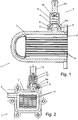
- the in Fig. 2 illustrated heat exchanger 1 is an exhaust gas cooler for an internal combustion engine comprising an outer housing 2, which is made as a plastic injection molded part.
- the housing 2 surrounds in the manner of a water jacket exchange means 11, which are formed as a bundle of flat tubes made of stainless steel.
- the flat tubes 11 carry in their interior the flow of hot exhaust gases of an internal combustion engine, wherein the exhaust gas flow is cooled by circulating in the housing 2 and the exchanger tubes 11 flowing around the coolant.
- the housing 2 comprises two connections 3, 4 for the supply and discharge of the coolant.
- the one connection 3 is designed as a simple tube-like connection for attaching a flexible hose.
- the other connection 4 comprises a tubular stub 5 and a molding 6, which is formed as a lateral, flange-like Abkragung of the nozzle 5.
- the Abkragung 6 suitable gradations 6a.
- a control member 7 is formed as a thermostat with an expansion element as a functionally essential component and fixed directly to the formation of the nozzle 6 5 of the terminal 4.
- the determination is carried out by means of a correspondingly shaped housing 8 made of plastic, which has a corresponding with the Abkragung 6 connection area 9 in the manner of a shaping 6 cross-cap.
- a thermostat mechanism 12 is arranged with an expansion element in a known per se. In this case, the thermostat mechanism 12 is supported by a spring 10 against the terminal 4, so that the terminal. 4 with its formation 6 forms a functional part of the control element 7.
- control member 7 On its opposite side of the terminal 4, the control member has a pipe socket 13 which corresponds in shape to the terminal 3 of the housing 2 and is used for easy attachment of a flexible hose in a known manner.
- the control member 7 is thus serially integrated into the coolant flow and fixed directly to the material integrally integrally molded housing 2, to which the housing 2 has a specially adapted molding 6 for cooperation with the control member 7.
- control element can be arranged on the inlet side or also on the outlet side of the housing 2. Depending on the temperature of the coolant, another passage cross section of the control element 7 is established.
- control element can be used to prevent overheating of the internal combustion engine if too much heat is released from the exhaust gas via the heat exchanger into the coolant.
Landscapes
- Engineering & Computer Science (AREA)
- Mechanical Engineering (AREA)
- General Engineering & Computer Science (AREA)
- Physics & Mathematics (AREA)
- Thermal Sciences (AREA)
- Chemical & Material Sciences (AREA)
- Combustion & Propulsion (AREA)
- Heat-Exchange Devices With Radiators And Conduit Assemblies (AREA)
- Exhaust Silencers (AREA)
Description
- Die vorliegende Erfindung betrifft einen Wärmetauscher, insbesondere für ein Kraftfahrzeug, nach dem Oberbegriff des Anspruchs 1.
US 2 864 589 offenbart einen derartigen Wärmetauscher. Im Bau von Wärmetauschern für Kraftfahrzeuge existieren Innovationen wie z. B. Abgaskühler zur Kühlung von zur Reduktion von Schadstoffen rückgeführtem Abgas eines Verbrennungsmotors. Gefordert sind dabei nicht nur grundsätzlich funktionierende Systeme, sondern auch die Reduktion von Kosten durch Verringerung der Anzahl von Bauteilen und Montageaufwand. - Es ist bekannt, Wärmetauscher wie z. B. Abgaskühler zur Regelung eines Kühlmittelstroms mit einem Thermostat zu versehen. Das Thermostat muss über geeignete Adapter in die Kühlmittelleitungen eingebracht werden. Hierdurch entsteht Aufwand bezüglich der Montage und der Anzahl der erforderlichen Bauteile.
- Es ist die Aufgabe der Erfindung, einen Wärmetauscher insbesondere für ein Kraftfahrzeug anzugeben, bei dem die Herstellungskosten und der Montageaufwand verringert sind.
- Diese Aufgabe wird für einen eingangs genannten Wärmetauscher erfindungsgemäß mit den kennzeichnenden Merkmalen des Anspruchs 1 gelöst. Durch das Vorsehen einer geeigneten Ausformung an dem Anschluss des Gehäuses ist die Anbringung eines Regelglieds auf besonders einfache Weise möglich und die Anzahl von benötigten Bauteilen zur Integration eines Regelglieds in den Fluidkreislauf wird reduziert. Erfindungsgemäß besteht das Gehäuse aus einem Kunststoff, wobei die Ausformung materialeinheitlich einstückig mit dem Gehäuse ausgebildet ist. Auf einfache Weise kann dies dadurch geschehen, dass das Gehäuse als Spritzgussteil hergestellt wird. Somit erfordert die Bereitstellung einer Ausformung zur Festlegung des Regelglieds lediglich einen einmaligen Aufwand bei der Gestaltung der Spritzgussform. In bevorzugter Ausführung ist das Regelglied dabei ein Thermostat mit einer thermomechanischen Einstellung des Fluidstroms. Unter thermomechanisch ist zu verstehen, dass eine Temperaturänderung des Fluids sich unmittelbar mechanisch, zum Beispiel durch Längenänderungen von geeigneten Komponenten, auf die Einstellung auswirkt. Bevorzugt umfasst das Thermostat dabei ein Dehnstoffelement. Solche Dehnstoffelemente, z. B. auf Wachsbasis, sind für Thermostatregler verbreitet und gut geeignet. Grundsätzlich können aber auch andere geeignete Bauteile wie zum Beispiel Bimetallstreifen, Memory-Metalle oder ähnliches Verwendung finden.
- In bevorzugter Weiterbildung kann das Thermostat auch als Kennfeld-Thermostat ausgebildet sein. Bei solchen Kennfeld-Thermostaten liegt grundsätzlich eine thermomechanische Regelung z. B. über Dehnstoffelemente vor, wobei diese Regelung über eine zusätzliche elektrische Heizung in ihrer Kennlinie beeinflusst werden kann. Hierdurch lässt sich eine Feinoptimierung der Regelungscharakteristik des Regelglieds auf einfache Weise erzielen, wobei auch bei Ausfall der elektrischen Beeinflussung die grundsätzliche Funktion gewährleistet ist.
- Zur weiteren Vereinfachung ist es vorteilhaft vorgesehen, dass eine Feder des Regelglieds gegen den Anschluss des Gehäuses abgestützt ist. Hierdurch wird der Anschluss des Gehäuses bzw. seine zur Festlegung des Regelglieds angepasste Ausformung als funktioneller Bestandteil des Regelglieds einbezogen, so dass besonders weitegehend Material und Bauteile eingespart werden können und der benötigte Bauraum reduziert wird.
- Zweckmäßig ist an der Ausformung ein Dichtmittel angeordnet, um eine zuverlässige Abdichtung des Fluidstroms bei aufgesetztem Regelglied zu gewährleisten.
- Allgemein vorteilhaft ist der Anschluss auf einfache Weise als rohrartiger Stutzen ausgebildet, wobei die Ausformung eine seitliche Abkragung des Stutzens umfasst. Eine solche seitliche Abkragung kann je nach Detailgestaltung als verschraubbarer Flansch ausgeformt sein oder als Komponente eines rastenden oder formschlüssigen Verschlusses. In einer bevorzugten Ausführung kann dabei das Regelglied rastend an der Ausformung festgelegt sein. Dies kann z. B. mittels federnder Haken erfolgen, die über die Ausformung oder seitliche Abkragung des Stutzens geschoben werden und hinterschneidend einrasten. Alternativ oder ergänzend kann das Regelglied auch nach Art eines Bajonettverschlusses an der Ausformung festgelegt sein, wobei die Festlegung auf formschlüssige Weise mittels einer axialen und zugleich überlagerten Drehbewegung erfolgt. Auch jede andere denkbare Art der einfachen Festlegung des Regelglieds an der Ausformung ist möglich, zum Beispiel mittels Klammern, Schellen, Halteringen etc... Zum Beispiel die Ausformung auch als Gewinde ausgebildet sein, so dass das Regelglied unmittelbar auf die Ausformung aufgeschraubt wird.
- Ein erfindungsgemäßer Wärmetauscher ist besonders in Ausbildung als Abgaskühler geeignet, wobei das zweite Fluid zumindest teilweise aus Abgas eines Verbrennungsmotors besteht. Das erste Fluid ist bevorzugt ein Kühlmittel eines Kühlkreislaufs eines Verbrennungsmotors. Bei einer solchen Verwendung ist es gewünscht, dass das Kühlmittel, das z. B. aus dem Kühlmittelkreislauf des Verbrennungsmotors abzweigt, über das Regelglied vor einem zu hohen Wärmeeintrag durch das Abgas geschützt wird, um eine Überhitzung des Verbrennungsmotors durch die Abgaskühlung zu vermeiden.
- Weitere Vorteile und Merkmale der Erfindung ergeben sich aus dem nachfolgend beschriebenen Ausführungsbeispiel sowie aus den abhängigen Ansprüchen.
- Nachfolgend wird ein bevorzugtes Ausführungsbeispiel einer erfindungsgemäßen Vorrichtung beschrieben und anhand der anliegenden Zeichnungen näher erläutert.
- Fig. 1
- zeigt eine schematische Schnittdarstellung eines Wärmetauschers mit einem daran vorgesehenen Regelglied.
- Fig. 2
- zeigt eine Draufsicht auf den Wärmetauscher aus
Fig. 1 von vorne. - Der in
Fig. 2 dargestellte Wärmetauscher 1 ist ein Abgaskühler für einen Verbrennungsmotor, der ein äußeres Gehäuse 2 umfasst, das als Kunststoff-Spritzgussteil hergestellt ist. Das Gehäuse 2 umfängt nach Art eines Wassermantels Tauschermittel 11, die als Bündel von Flachrohren aus nichtrostendem Stahl ausgebildet sind. Die Flachrohre 11 führen in ihrem Inneren den Strom aus heißen Abgasen eines Verbrennungsmotors, wobei der Abgasstrom mittels in dem Gehäuse 2 zirkulierenden und die Tauscherrohre 11 umströmenden Kühlmittels gekühlt wird. Hierzu umfasst das Gehäuse 2 zwei Anschlüsse 3, 4 zur Zuführung und Abführung des Kühlmittels. Der eine Anschluss 3 ist dabei als einfacher rohrartiger Stutzen zur Anbringung einer flexiblen Schlauchleitung ausgebildet. Der andere Anschluss 4 umfasst einen rohrartigen Stutzen 5 und eine Ausformung 6, die als seitliche, flanschartige Abkragung des Stutzens 5 ausgebildet ist. Zur Positionierung eines Dichtungsrings umfasst die Abkragung 6 geeignete Abstufungen 6a. - Ein Regelglied 7 ist als Thermostat mit einem Dehnstoff-Element als funktionswesentliches Bauteil ausgebildet und unmittelbar an der Ausformung 6 des Stutzens 5 des Anschlusses 4 festgelegt. Die Festlegung erfolgt mittels eines entsprechend ausgeformten Gehäuses 8 aus Kunststoff, das einen mit der Abkragung 6 korrespondierenden Anschlussbereich 9 nach Art einer die Ausformung 6 übergreifenden Kappe aufweist. Innerhalb des Gehäuses 8 ist eine Thermostatmechanik 12 mit einem Dehnstoffelement auf an sich bekannte Weise angeordnet. Dabei ist die Thermostatmechanik 12 mittels einer Feder 10 gegen den Anschluss 4 abgestützt, so dass der Anschluss 4 mit seiner Ausformung 6 einen funktionalen Bestandteil des Regelglieds 7 ausbildet.
- Auf seiner dem Anschluss 4 entgegengesetzten Seite hat das Regelglied einen Rohrstutzen 13, der in seiner Form dem Anschluss 3 des Gehäuses 2 entspricht und zur einfachen Anbringung einer flexiblen Schlauchleitung auf bekannte Weise dient. Das Regelglied 7 ist somit seriell in den Kühlmittelstrom integriert und unmittelbar an dem materialeinheitlich einstückig ausgeformten Gehäuse 2 festgelegt, wozu das Gehäuse 2 eine speziell angepasste Ausformung 6 zum Zusammenwirken mit dem Regelglied 7 aufweist.
- Grundsätzlich kann das Regelglied eintrittsseitig oder auch austrittsseitig des Gehäuses 2 angeordnet sein. Je nach Temperatur des Kühlmittels stellt sich ein anderer Durchtrittsquerschnitt des Regelglieds 7 ein. So kann das Regelglied zum Beispiel dazu eingesetzt werden, eine Überhitzung des Verbrennungsmotors zu vermeiden, falls zuviel Wärmemenge von dem Abgas über den Wärmetauscher in das Kühlmittel abgegeben wird.
Claims (12)
- Wärmetauscher, insbesondere für ein Kraftfahrzeug, umfassend ein Gehäuse (2) mit einem Anschluss (4) für den Einlass oder Auslass eines erstes Fluids, wobei das Gehäuse (2) von dem ersten Fluid durchströmbar ist und wobei in dem Gehäuse (2) Tauschermittel (11) zur Durchströmung mit einem zweiten Fluid angeordnet sind, wobei das erste Fluid ein Regelglied (7) durchströmt, mittels dessen die Strömung des ersten Fluids veränderbar ist, wobei der Anschluss (4) eine Ausformung (6) zur Halterung des Regelglieds (7) aufweist, dadurch gekennzeichnet, dass das Gehäuse (2) aus einem Kunststoff besteht, wobei die Ausformung (6) materialeinheitlich einstückig mit dem Gehäuse (2) ausgebildet ist.
- Wärmetauscher nach Anspruch 1, dadurch gekennzeichnet, dass das Regelglied (7) als ein Thermostat mit einer thermomechanischen Einstellung des Fluidstroms ist.
- Wärmetauscher nach Anspruch 2, dadurch gekennzeichnet, dass das Thermostat (7) ein Dehnstoffelement (12) umfasst.
- Wärmetauscher nach einem der Ansprüche 2 oder 3, dadurch gekennzeichnet, dass das Thermostat (7) als Kennfeld-Thermostat ausgebildet ist.
- Wärmetauscher nach einem der vorhergehenden Ansprüche, dadurch gekennzeichnet, dass eine Feder (10) des Regelglieds (7) gegen den Anschluss (4) des Gehäuses (2) abgestützt ist.
- Wärmetauscher nach einem der vorhergehenden Ansprüche, dadurch gekennzeichnet, dass ein Dichtmittel an der Ausformung (6) angeordnet ist.
- Wärmetauscher nach einem der vorhergehenden Ansprüche, dadurch gekennzeichnet, dass der Anschluss (4) als rohrartiger Stutzen (5) ausgebildet ist, wobei die Ausformung (6) eine seitliche Abkragung des Stutzens (5) umfasst.
- Wärmetauscher nach einem der vorhergehenden Ansprüche, dadurch gekennzeichnet, dass das Regelglied (7) mit der Ausformung (6) verschraubt ist.
- Wärmetauscher nach einem der vorhergehenden Ansprüche, dadurch gekennzeichnet, dass das Regelglied (7) rastend an der Ausformung (6) festgelegt ist.
- Wärmetauscher nach einem der vorhergehenden Ansprüche, dadurch gekennzeichnet, dass das Regelglied (7) nach Art eines Bajonettverschlusses an der Ausformung (6) festgelegt ist.
- Wärmetauscher nach einem der vorhergehenden Ansprüche, dadurch gekennzeichnet, dass der Wärmetauscher ein Abgaskühler (1) ist, wobei das zweite Fluid zumindest teilweise aus Abgas eines Verbrennungsmotors besteht.
- Wärmetauscher nach einem der vorhergehenden Ansprüche, dadurch gekennzeichnet, dass das erste Fluid ein Kühlmittel eines Kühlkreislaufs eines Verbrennungsmotors ist.
Applications Claiming Priority (2)
| Application Number | Priority Date | Filing Date | Title |
|---|---|---|---|
| DE102006052526A DE102006052526A1 (de) | 2006-11-06 | 2006-11-06 | Wärmetauscher, insbesondere für ein Kraftfahrzeug |
| PCT/EP2007/009582 WO2008055642A1 (de) | 2006-11-06 | 2007-11-06 | Wärmetauscher, insbesondere für ein kraftfahrzeug |
Publications (2)
| Publication Number | Publication Date |
|---|---|
| EP2087221A1 EP2087221A1 (de) | 2009-08-12 |
| EP2087221B1 true EP2087221B1 (de) | 2018-09-05 |
Family
ID=38969926
Family Applications (1)
| Application Number | Title | Priority Date | Filing Date |
|---|---|---|---|
| EP07846531.7A Not-in-force EP2087221B1 (de) | 2006-11-06 | 2007-11-06 | Wärmetauscher, insbesondere für ein kraftfahrzeug |
Country Status (4)
| Country | Link |
|---|---|
| US (1) | US20100051255A1 (de) |
| EP (1) | EP2087221B1 (de) |
| DE (1) | DE102006052526A1 (de) |
| WO (1) | WO2008055642A1 (de) |
Families Citing this family (4)
| Publication number | Priority date | Publication date | Assignee | Title |
|---|---|---|---|---|
| FR2938322B1 (fr) * | 2008-11-07 | 2010-12-03 | Valeo Sys Controle Moteur Sas | Echangeur thermique comportant un profile incluant des conduites et une coque entourant ce profile |
| FR3008175A1 (fr) * | 2013-07-04 | 2015-01-09 | Valeo Systemes Thermiques | Dispositif de regulation de la circulation d'un liquide de refroidissement pour un echangeur de chaleur, en particulier refroidisseur d'air de suralimentation de moteur de vehicule automobile |
| US10400714B2 (en) * | 2017-09-28 | 2019-09-03 | Senior Ip Gmbh | Heat exchanger with annular coolant chamber |
| DE102022209294A1 (de) * | 2022-09-07 | 2024-03-07 | Robert Bosch Gesellschaft mit beschränkter Haftung | Kühlkreislaufvorrichtung |
Citations (1)
| Publication number | Priority date | Publication date | Assignee | Title |
|---|---|---|---|---|
| US2864589A (en) * | 1955-06-14 | 1958-12-16 | United Aircraft Prod | Heat transfer device |
Family Cites Families (16)
| Publication number | Priority date | Publication date | Assignee | Title |
|---|---|---|---|---|
| AT299724B (de) * | 1968-07-29 | 1972-06-26 | Eberspaecher J | Wärmetauscher, vorzugsweise für Kraftfahrzeugheizungen |
| US4000849A (en) * | 1972-12-06 | 1977-01-04 | Robertshaw Controls Company | Temperature responsive valve |
| DE3828034A1 (de) * | 1988-08-18 | 1990-02-22 | Borsig Gmbh | Waermetauscher |
| DE19606202B4 (de) * | 1996-02-21 | 2010-07-01 | Behr Thermot-Tronik Gmbh | Kühlsystem für einen Verbrennungsmotor |
| DE19754797A1 (de) * | 1997-12-10 | 1999-06-17 | Behr Gmbh & Co | Entgasungsvorrichtung |
| DE29722813U1 (de) * | 1997-12-24 | 1999-04-22 | Behr Thermot-Tronik Gmbh & Co., 70806 Kornwestheim | Abgasrückführungseinrichtung für einen Verbrennungsmotor eines Kraftfahrzeuges |
| DE19902885C1 (de) * | 1999-01-26 | 2000-05-31 | Delta Radiatoren Gmbh | Heizkörper, insbesondere Röhrenradiator |
| FR2811709B1 (fr) * | 2000-07-17 | 2003-02-21 | Vernet Sa | Dispositif thermostatique pilote a commande proportionnelle, a element thermostatique de securite |
| US6976480B2 (en) * | 2002-01-16 | 2005-12-20 | Mitsubishi Denki Kabushiki Kaisha | Exhaust gas recirculating device |
| DE50311520D1 (de) * | 2002-05-15 | 2009-06-25 | Behr Gmbh & Co Kg | Schaltbarer abgaswaermetauscher |
| DE20316688U1 (de) * | 2003-10-29 | 2004-03-11 | Behr Gmbh & Co. Kg | Wärmetauscher |
| US7108193B2 (en) * | 2003-12-29 | 2006-09-19 | Wahler Metalurgica Ltda | Integration of a thermostat in the recycling system of the vehicular exhaust gas recirculation (EGR) system |
| DE102004045021B4 (de) * | 2004-09-15 | 2013-07-11 | Behr Gmbh & Co. Kg | Wärmetauscher für Verbrennungsmotoren |
| FR2879711B1 (fr) * | 2004-12-21 | 2007-02-09 | Vernet Sa | Vanne thermostatique de regulation d'un fluide et circuit de refroidissement incorporant une telle vanne |
| DE102005057674B4 (de) * | 2005-12-01 | 2008-05-08 | Alstom Technology Ltd. | Abhitzekessel |
| US20100084111A1 (en) * | 2006-07-11 | 2010-04-08 | Brunswick Corporation | Liquid to liquid heat exchanger for a marine engine cooling system |
-
2006
- 2006-11-06 DE DE102006052526A patent/DE102006052526A1/de not_active Withdrawn
-
2007
- 2007-11-06 WO PCT/EP2007/009582 patent/WO2008055642A1/de not_active Ceased
- 2007-11-06 EP EP07846531.7A patent/EP2087221B1/de not_active Not-in-force
- 2007-11-06 US US12/513,170 patent/US20100051255A1/en not_active Abandoned
Patent Citations (1)
| Publication number | Priority date | Publication date | Assignee | Title |
|---|---|---|---|---|
| US2864589A (en) * | 1955-06-14 | 1958-12-16 | United Aircraft Prod | Heat transfer device |
Also Published As
| Publication number | Publication date |
|---|---|
| DE102006052526A1 (de) | 2008-05-08 |
| EP2087221A1 (de) | 2009-08-12 |
| US20100051255A1 (en) | 2010-03-04 |
| WO2008055642A1 (de) | 2008-05-15 |
Similar Documents
| Publication | Publication Date | Title |
|---|---|---|
| DE69100764T2 (de) | Erwärmer für Scheibenwaschflüssigkeit für Motorkühlflüssigkeitskreislauf. | |
| EP1967714B1 (de) | Kühlmittelregler und Verfahren zu dessen Herstellung | |
| DE69816891T2 (de) | Kühlungsanlage für eine Brennkraftmaschine, insbesondere für Kraftfahrzeuge | |
| EP1881171B1 (de) | Ventil zur Steuerung eines Kühlmittelstroms für einen Heizkörper eines Kraftfahrzeugs und System mit zumindest einem solchen Ventil | |
| DE19606202A1 (de) | Kühlsystem für einen Verbrennungsmotor | |
| WO1998012425A1 (de) | Einrichtung und verfahren zum kühlen und vorwärmen | |
| DE102007052706A1 (de) | Wärmetauscher | |
| EP2181375A2 (de) | Thermostatisches sicherheitsventil | |
| DE69801472T2 (de) | Abgasanlage für einen Kraftfahrzeugmotor | |
| DE4325975C5 (de) | Thermostatventil | |
| DE10119484B4 (de) | Flüssigkeitsgekühlte Brennkraftmaschine mit einem Abgasrückführsystem | |
| DE102010010624A1 (de) | Koaxialer Wärmetauscher für eine Kraftfahrzeug-Abgasanlage | |
| EP2087221A1 (de) | Wärmetauscher, insbesondere für ein kraftfahrzeug | |
| DE102010033125A1 (de) | Wärmetauschereinrichtung | |
| DE19506935C1 (de) | Kühlmittelkreislauf für einen Verbrennungsmotor eines Kraftfahrzeugs | |
| DE102019123181A1 (de) | Thermostat und Kühlmittelleitungsaufbau | |
| EP3527800B1 (de) | Kühlkreislauf für eine antriebseinheit eines kraftfahrzeuges | |
| DE102008060224B4 (de) | Öl-Abgas-Kühlmodul für eine Verbrennungskraftmaschine | |
| DE102004062908A1 (de) | Sensor und Verfahren zum Herstellen eines Sensors | |
| DE10346195B4 (de) | Thermostatventil | |
| EP3510835B1 (de) | Ringförmiges heizelement | |
| DE10340908A1 (de) | Brennkraftmaschine für Kraftfahrzeuge | |
| DE102004030153A1 (de) | Kühlkreislauf für eine Brennkraftmaschine | |
| DE102007022859A1 (de) | Anordnung von in Reihe geschalteten Heizungswärmeaustauschern in einem Kraftfahrzeug | |
| DE102007052263B4 (de) | Thermostatventilanordnung |
Legal Events
| Date | Code | Title | Description |
|---|---|---|---|
| PUAI | Public reference made under article 153(3) epc to a published international application that has entered the european phase |
Free format text: ORIGINAL CODE: 0009012 |
|
| 17P | Request for examination filed |
Effective date: 20090608 |
|
| AK | Designated contracting states |
Kind code of ref document: A1 Designated state(s): AT BE BG CH CY CZ DE DK EE ES FI FR GB GR HU IE IS IT LI LT LU LV MC MT NL PL PT RO SE SI SK TR |
|
| RIN1 | Information on inventor provided before grant (corrected) |
Inventor name: ROESCHMANN, TIMM Inventor name: EMRICH, KARSTEN Inventor name: CZEMMEL, HEINZ Inventor name: FRIESENHAHN, WALDEMAR |
|
| RIN1 | Information on inventor provided before grant (corrected) |
Inventor name: FRIESENHAHN, WALDEMAR Inventor name: CZEMMEL, HEINZ Inventor name: EMRICH, KARSTEN Inventor name: ROESCHMANN, TIMM |
|
| 17Q | First examination report despatched |
Effective date: 20090921 |
|
| DAX | Request for extension of the european patent (deleted) | ||
| RAP1 | Party data changed (applicant data changed or rights of an application transferred) |
Owner name: MAHLE BEHR GMBH & CO. KG Owner name: BEHR THERMOT-TRONIK GMBH |
|
| RAP1 | Party data changed (applicant data changed or rights of an application transferred) |
Owner name: MAHLE BEHR GMBH & CO. KG Owner name: MAHLE BEHR KORNWESTHEIM GMBH |
|
| REG | Reference to a national code |
Ref country code: DE Ref legal event code: R079 Ref document number: 502007016377 Country of ref document: DE Free format text: PREVIOUS MAIN CLASS: F02M0025070000 Ipc: F02M0026220000 |
|
| GRAP | Despatch of communication of intention to grant a patent |
Free format text: ORIGINAL CODE: EPIDOSNIGR1 |
|
| RIC1 | Information provided on ipc code assigned before grant |
Ipc: F02M 26/33 20160101ALI20180419BHEP Ipc: F02M 26/22 20160101AFI20180419BHEP Ipc: F02M 26/32 20160101ALI20180419BHEP Ipc: F28F 9/02 20060101ALI20180419BHEP Ipc: F01P 3/18 20060101ALI20180419BHEP Ipc: F28F 21/06 20060101ALI20180419BHEP Ipc: F28D 21/00 20060101ALI20180419BHEP Ipc: F28D 7/16 20060101ALI20180419BHEP Ipc: F28F 27/02 20060101ALI20180419BHEP Ipc: F01P 7/16 20060101ALI20180419BHEP Ipc: F02M 26/30 20160101ALI20180419BHEP |
|
| INTG | Intention to grant announced |
Effective date: 20180522 |
|
| GRAS | Grant fee paid |
Free format text: ORIGINAL CODE: EPIDOSNIGR3 |
|
| GRAA | (expected) grant |
Free format text: ORIGINAL CODE: 0009210 |
|
| AK | Designated contracting states |
Kind code of ref document: B1 Designated state(s): AT BE BG CH CY CZ DE DK EE ES FI FR GB GR HU IE IS IT LI LT LU LV MC MT NL PL PT RO SE SI SK TR |
|
| REG | Reference to a national code |
Ref country code: GB Ref legal event code: FG4D Free format text: NOT ENGLISH |
|
| RIN1 | Information on inventor provided before grant (corrected) |
Inventor name: CZEMMEL, HEINZ Inventor name: EMRICH, KARSTEN Inventor name: ROESCHMANN, TIMM Inventor name: FRIESENHAHN, WALDEMAR |
|
| REG | Reference to a national code |
Ref country code: CH Ref legal event code: EP |
|
| REG | Reference to a national code |
Ref country code: AT Ref legal event code: REF Ref document number: 1038103 Country of ref document: AT Kind code of ref document: T Effective date: 20180915 |
|
| REG | Reference to a national code |
Ref country code: IE Ref legal event code: FG4D Free format text: LANGUAGE OF EP DOCUMENT: GERMAN |
|
| REG | Reference to a national code |
Ref country code: DE Ref legal event code: R096 Ref document number: 502007016377 Country of ref document: DE |
|
| REG | Reference to a national code |
Ref country code: NL Ref legal event code: MP Effective date: 20180905 |
|
| REG | Reference to a national code |
Ref country code: LT Ref legal event code: MG4D |
|
| PG25 | Lapsed in a contracting state [announced via postgrant information from national office to epo] |
Ref country code: BG Free format text: LAPSE BECAUSE OF FAILURE TO SUBMIT A TRANSLATION OF THE DESCRIPTION OR TO PAY THE FEE WITHIN THE PRESCRIBED TIME-LIMIT Effective date: 20181205 Ref country code: LT Free format text: LAPSE BECAUSE OF FAILURE TO SUBMIT A TRANSLATION OF THE DESCRIPTION OR TO PAY THE FEE WITHIN THE PRESCRIBED TIME-LIMIT Effective date: 20180905 Ref country code: GR Free format text: LAPSE BECAUSE OF FAILURE TO SUBMIT A TRANSLATION OF THE DESCRIPTION OR TO PAY THE FEE WITHIN THE PRESCRIBED TIME-LIMIT Effective date: 20181206 Ref country code: FI Free format text: LAPSE BECAUSE OF FAILURE TO SUBMIT A TRANSLATION OF THE DESCRIPTION OR TO PAY THE FEE WITHIN THE PRESCRIBED TIME-LIMIT Effective date: 20180905 Ref country code: SE Free format text: LAPSE BECAUSE OF FAILURE TO SUBMIT A TRANSLATION OF THE DESCRIPTION OR TO PAY THE FEE WITHIN THE PRESCRIBED TIME-LIMIT Effective date: 20180905 |
|
| PGFP | Annual fee paid to national office [announced via postgrant information from national office to epo] |
Ref country code: DE Payment date: 20181203 Year of fee payment: 12 |
|
| PG25 | Lapsed in a contracting state [announced via postgrant information from national office to epo] |
Ref country code: LV Free format text: LAPSE BECAUSE OF FAILURE TO SUBMIT A TRANSLATION OF THE DESCRIPTION OR TO PAY THE FEE WITHIN THE PRESCRIBED TIME-LIMIT Effective date: 20180905 Ref country code: ES Free format text: LAPSE BECAUSE OF FAILURE TO SUBMIT A TRANSLATION OF THE DESCRIPTION OR TO PAY THE FEE WITHIN THE PRESCRIBED TIME-LIMIT Effective date: 20180905 |
|
| PG25 | Lapsed in a contracting state [announced via postgrant information from national office to epo] |
Ref country code: EE Free format text: LAPSE BECAUSE OF FAILURE TO SUBMIT A TRANSLATION OF THE DESCRIPTION OR TO PAY THE FEE WITHIN THE PRESCRIBED TIME-LIMIT Effective date: 20180905 Ref country code: PL Free format text: LAPSE BECAUSE OF FAILURE TO SUBMIT A TRANSLATION OF THE DESCRIPTION OR TO PAY THE FEE WITHIN THE PRESCRIBED TIME-LIMIT Effective date: 20180905 Ref country code: IS Free format text: LAPSE BECAUSE OF FAILURE TO SUBMIT A TRANSLATION OF THE DESCRIPTION OR TO PAY THE FEE WITHIN THE PRESCRIBED TIME-LIMIT Effective date: 20190105 Ref country code: RO Free format text: LAPSE BECAUSE OF FAILURE TO SUBMIT A TRANSLATION OF THE DESCRIPTION OR TO PAY THE FEE WITHIN THE PRESCRIBED TIME-LIMIT Effective date: 20180905 Ref country code: IT Free format text: LAPSE BECAUSE OF FAILURE TO SUBMIT A TRANSLATION OF THE DESCRIPTION OR TO PAY THE FEE WITHIN THE PRESCRIBED TIME-LIMIT Effective date: 20180905 Ref country code: NL Free format text: LAPSE BECAUSE OF FAILURE TO SUBMIT A TRANSLATION OF THE DESCRIPTION OR TO PAY THE FEE WITHIN THE PRESCRIBED TIME-LIMIT Effective date: 20180905 Ref country code: CZ Free format text: LAPSE BECAUSE OF FAILURE TO SUBMIT A TRANSLATION OF THE DESCRIPTION OR TO PAY THE FEE WITHIN THE PRESCRIBED TIME-LIMIT Effective date: 20180905 |
|
| PG25 | Lapsed in a contracting state [announced via postgrant information from national office to epo] |
Ref country code: PT Free format text: LAPSE BECAUSE OF FAILURE TO SUBMIT A TRANSLATION OF THE DESCRIPTION OR TO PAY THE FEE WITHIN THE PRESCRIBED TIME-LIMIT Effective date: 20190105 Ref country code: SK Free format text: LAPSE BECAUSE OF FAILURE TO SUBMIT A TRANSLATION OF THE DESCRIPTION OR TO PAY THE FEE WITHIN THE PRESCRIBED TIME-LIMIT Effective date: 20180905 |
|
| REG | Reference to a national code |
Ref country code: DE Ref legal event code: R097 Ref document number: 502007016377 Country of ref document: DE |
|
| REG | Reference to a national code |
Ref country code: CH Ref legal event code: PL |
|
| PLBE | No opposition filed within time limit |
Free format text: ORIGINAL CODE: 0009261 |
|
| STAA | Information on the status of an ep patent application or granted ep patent |
Free format text: STATUS: NO OPPOSITION FILED WITHIN TIME LIMIT |
|
| PG25 | Lapsed in a contracting state [announced via postgrant information from national office to epo] |
Ref country code: DK Free format text: LAPSE BECAUSE OF FAILURE TO SUBMIT A TRANSLATION OF THE DESCRIPTION OR TO PAY THE FEE WITHIN THE PRESCRIBED TIME-LIMIT Effective date: 20180905 Ref country code: LU Free format text: LAPSE BECAUSE OF NON-PAYMENT OF DUE FEES Effective date: 20181106 Ref country code: MC Free format text: LAPSE BECAUSE OF FAILURE TO SUBMIT A TRANSLATION OF THE DESCRIPTION OR TO PAY THE FEE WITHIN THE PRESCRIBED TIME-LIMIT Effective date: 20180905 |
|
| 26N | No opposition filed |
Effective date: 20190606 |
|
| REG | Reference to a national code |
Ref country code: BE Ref legal event code: MM Effective date: 20181130 |
|
| REG | Reference to a national code |
Ref country code: IE Ref legal event code: MM4A |
|
| GBPC | Gb: european patent ceased through non-payment of renewal fee |
Effective date: 20181205 |
|
| PG25 | Lapsed in a contracting state [announced via postgrant information from national office to epo] |
Ref country code: SI Free format text: LAPSE BECAUSE OF FAILURE TO SUBMIT A TRANSLATION OF THE DESCRIPTION OR TO PAY THE FEE WITHIN THE PRESCRIBED TIME-LIMIT Effective date: 20180905 Ref country code: CH Free format text: LAPSE BECAUSE OF NON-PAYMENT OF DUE FEES Effective date: 20181130 Ref country code: LI Free format text: LAPSE BECAUSE OF NON-PAYMENT OF DUE FEES Effective date: 20181130 |
|
| PG25 | Lapsed in a contracting state [announced via postgrant information from national office to epo] |
Ref country code: FR Free format text: LAPSE BECAUSE OF NON-PAYMENT OF DUE FEES Effective date: 20181130 Ref country code: IE Free format text: LAPSE BECAUSE OF NON-PAYMENT OF DUE FEES Effective date: 20181106 |
|
| PG25 | Lapsed in a contracting state [announced via postgrant information from national office to epo] |
Ref country code: BE Free format text: LAPSE BECAUSE OF NON-PAYMENT OF DUE FEES Effective date: 20181130 |
|
| PG25 | Lapsed in a contracting state [announced via postgrant information from national office to epo] |
Ref country code: GB Free format text: LAPSE BECAUSE OF NON-PAYMENT OF DUE FEES Effective date: 20181205 |
|
| REG | Reference to a national code |
Ref country code: AT Ref legal event code: MM01 Ref document number: 1038103 Country of ref document: AT Kind code of ref document: T Effective date: 20181106 |
|
| PG25 | Lapsed in a contracting state [announced via postgrant information from national office to epo] |
Ref country code: MT Free format text: LAPSE BECAUSE OF FAILURE TO SUBMIT A TRANSLATION OF THE DESCRIPTION OR TO PAY THE FEE WITHIN THE PRESCRIBED TIME-LIMIT Effective date: 20180905 Ref country code: AT Free format text: LAPSE BECAUSE OF NON-PAYMENT OF DUE FEES Effective date: 20181106 |
|
| PG25 | Lapsed in a contracting state [announced via postgrant information from national office to epo] |
Ref country code: TR Free format text: LAPSE BECAUSE OF FAILURE TO SUBMIT A TRANSLATION OF THE DESCRIPTION OR TO PAY THE FEE WITHIN THE PRESCRIBED TIME-LIMIT Effective date: 20180905 |
|
| REG | Reference to a national code |
Ref country code: DE Ref legal event code: R119 Ref document number: 502007016377 Country of ref document: DE |
|
| PG25 | Lapsed in a contracting state [announced via postgrant information from national office to epo] |
Ref country code: HU Free format text: LAPSE BECAUSE OF FAILURE TO SUBMIT A TRANSLATION OF THE DESCRIPTION OR TO PAY THE FEE WITHIN THE PRESCRIBED TIME-LIMIT; INVALID AB INITIO Effective date: 20071106 Ref country code: CY Free format text: LAPSE BECAUSE OF FAILURE TO SUBMIT A TRANSLATION OF THE DESCRIPTION OR TO PAY THE FEE WITHIN THE PRESCRIBED TIME-LIMIT Effective date: 20180905 |
|
| PG25 | Lapsed in a contracting state [announced via postgrant information from national office to epo] |
Ref country code: DE Free format text: LAPSE BECAUSE OF NON-PAYMENT OF DUE FEES Effective date: 20200603 |