EP2082667B1 - Dämpfungseinrichtung für bewegbare Möbelteile - Google Patents
Dämpfungseinrichtung für bewegbare Möbelteile Download PDFInfo
- Publication number
- EP2082667B1 EP2082667B1 EP08169374.9A EP08169374A EP2082667B1 EP 2082667 B1 EP2082667 B1 EP 2082667B1 EP 08169374 A EP08169374 A EP 08169374A EP 2082667 B1 EP2082667 B1 EP 2082667B1
- Authority
- EP
- European Patent Office
- Prior art keywords
- gear
- gear wheel
- freewheel
- driver
- damping device
- Prior art date
- Legal status (The legal status is an assumption and is not a legal conclusion. Google has not performed a legal analysis and makes no representation as to the accuracy of the status listed.)
- Not-in-force
Links
- 238000013016 damping Methods 0.000 claims description 26
- 238000000034 method Methods 0.000 claims 1
- 230000005540 biological transmission Effects 0.000 description 6
- 238000006073 displacement reaction Methods 0.000 description 3
- 230000000694 effects Effects 0.000 description 2
- 230000001419 dependent effect Effects 0.000 description 1
- 239000012530 fluid Substances 0.000 description 1
- 238000002347 injection Methods 0.000 description 1
- 239000007924 injection Substances 0.000 description 1
- 238000004519 manufacturing process Methods 0.000 description 1
Images




Classifications
-
- E—FIXED CONSTRUCTIONS
- E05—LOCKS; KEYS; WINDOW OR DOOR FITTINGS; SAFES
- E05F—DEVICES FOR MOVING WINGS INTO OPEN OR CLOSED POSITION; CHECKS FOR WINGS; WING FITTINGS NOT OTHERWISE PROVIDED FOR, CONCERNED WITH THE FUNCTIONING OF THE WING
- E05F5/00—Braking devices, e.g. checks; Stops; Buffers
- E05F5/003—Braking devices, e.g. checks; Stops; Buffers for sliding wings
-
- A—HUMAN NECESSITIES
- A47—FURNITURE; DOMESTIC ARTICLES OR APPLIANCES; COFFEE MILLS; SPICE MILLS; SUCTION CLEANERS IN GENERAL
- A47B—TABLES; DESKS; OFFICE FURNITURE; CABINETS; DRAWERS; GENERAL DETAILS OF FURNITURE
- A47B88/00—Drawers for tables, cabinets or like furniture; Guides for drawers
- A47B88/40—Sliding drawers; Slides or guides therefor
- A47B88/453—Actuated drawers
- A47B88/46—Actuated drawers operated by mechanically-stored energy, e.g. by springs
- A47B88/467—Actuated drawers operated by mechanically-stored energy, e.g. by springs self-closing
-
- E—FIXED CONSTRUCTIONS
- E05—LOCKS; KEYS; WINDOW OR DOOR FITTINGS; SAFES
- E05F—DEVICES FOR MOVING WINGS INTO OPEN OR CLOSED POSITION; CHECKS FOR WINGS; WING FITTINGS NOT OTHERWISE PROVIDED FOR, CONCERNED WITH THE FUNCTIONING OF THE WING
- E05F1/00—Closers or openers for wings, not otherwise provided for in this subclass
- E05F1/08—Closers or openers for wings, not otherwise provided for in this subclass spring-actuated, e.g. for horizontally sliding wings
- E05F1/16—Closers or openers for wings, not otherwise provided for in this subclass spring-actuated, e.g. for horizontally sliding wings for sliding wings
-
- E—FIXED CONSTRUCTIONS
- E05—LOCKS; KEYS; WINDOW OR DOOR FITTINGS; SAFES
- E05Y—INDEXING SCHEME ASSOCIATED WITH SUBCLASSES E05D AND E05F, RELATING TO CONSTRUCTION ELEMENTS, ELECTRIC CONTROL, POWER SUPPLY, POWER SIGNAL OR TRANSMISSION, USER INTERFACES, MOUNTING OR COUPLING, DETAILS, ACCESSORIES, AUXILIARY OPERATIONS NOT OTHERWISE PROVIDED FOR, APPLICATION THEREOF
- E05Y2201/00—Constructional elements; Accessories therefor
- E05Y2201/20—Brakes; Disengaging means; Holders; Stops; Valves; Accessories therefor
- E05Y2201/21—Brakes
-
- E—FIXED CONSTRUCTIONS
- E05—LOCKS; KEYS; WINDOW OR DOOR FITTINGS; SAFES
- E05Y—INDEXING SCHEME ASSOCIATED WITH SUBCLASSES E05D AND E05F, RELATING TO CONSTRUCTION ELEMENTS, ELECTRIC CONTROL, POWER SUPPLY, POWER SIGNAL OR TRANSMISSION, USER INTERFACES, MOUNTING OR COUPLING, DETAILS, ACCESSORIES, AUXILIARY OPERATIONS NOT OTHERWISE PROVIDED FOR, APPLICATION THEREOF
- E05Y2201/00—Constructional elements; Accessories therefor
- E05Y2201/20—Brakes; Disengaging means; Holders; Stops; Valves; Accessories therefor
- E05Y2201/23—Actuation thereof
- E05Y2201/232—Actuation thereof by automatically acting means
- E05Y2201/234—Actuation thereof by automatically acting means direction dependent
-
- E—FIXED CONSTRUCTIONS
- E05—LOCKS; KEYS; WINDOW OR DOOR FITTINGS; SAFES
- E05Y—INDEXING SCHEME ASSOCIATED WITH SUBCLASSES E05D AND E05F, RELATING TO CONSTRUCTION ELEMENTS, ELECTRIC CONTROL, POWER SUPPLY, POWER SIGNAL OR TRANSMISSION, USER INTERFACES, MOUNTING OR COUPLING, DETAILS, ACCESSORIES, AUXILIARY OPERATIONS NOT OTHERWISE PROVIDED FOR, APPLICATION THEREOF
- E05Y2201/00—Constructional elements; Accessories therefor
- E05Y2201/20—Brakes; Disengaging means; Holders; Stops; Valves; Accessories therefor
- E05Y2201/252—Type of friction
- E05Y2201/254—Fluid or viscous friction
-
- E—FIXED CONSTRUCTIONS
- E05—LOCKS; KEYS; WINDOW OR DOOR FITTINGS; SAFES
- E05Y—INDEXING SCHEME ASSOCIATED WITH SUBCLASSES E05D AND E05F, RELATING TO CONSTRUCTION ELEMENTS, ELECTRIC CONTROL, POWER SUPPLY, POWER SIGNAL OR TRANSMISSION, USER INTERFACES, MOUNTING OR COUPLING, DETAILS, ACCESSORIES, AUXILIARY OPERATIONS NOT OTHERWISE PROVIDED FOR, APPLICATION THEREOF
- E05Y2201/00—Constructional elements; Accessories therefor
- E05Y2201/20—Brakes; Disengaging means; Holders; Stops; Valves; Accessories therefor
- E05Y2201/252—Type of friction
- E05Y2201/258—Magnetic or electromagnetic friction
-
- E—FIXED CONSTRUCTIONS
- E05—LOCKS; KEYS; WINDOW OR DOOR FITTINGS; SAFES
- E05Y—INDEXING SCHEME ASSOCIATED WITH SUBCLASSES E05D AND E05F, RELATING TO CONSTRUCTION ELEMENTS, ELECTRIC CONTROL, POWER SUPPLY, POWER SIGNAL OR TRANSMISSION, USER INTERFACES, MOUNTING OR COUPLING, DETAILS, ACCESSORIES, AUXILIARY OPERATIONS NOT OTHERWISE PROVIDED FOR, APPLICATION THEREOF
- E05Y2201/00—Constructional elements; Accessories therefor
- E05Y2201/20—Brakes; Disengaging means; Holders; Stops; Valves; Accessories therefor
- E05Y2201/262—Type of motion, e.g. braking
- E05Y2201/266—Type of motion, e.g. braking rotary
-
- E—FIXED CONSTRUCTIONS
- E05—LOCKS; KEYS; WINDOW OR DOOR FITTINGS; SAFES
- E05Y—INDEXING SCHEME ASSOCIATED WITH SUBCLASSES E05D AND E05F, RELATING TO CONSTRUCTION ELEMENTS, ELECTRIC CONTROL, POWER SUPPLY, POWER SIGNAL OR TRANSMISSION, USER INTERFACES, MOUNTING OR COUPLING, DETAILS, ACCESSORIES, AUXILIARY OPERATIONS NOT OTHERWISE PROVIDED FOR, APPLICATION THEREOF
- E05Y2201/00—Constructional elements; Accessories therefor
- E05Y2201/40—Motors; Magnets; Springs; Weights; Accessories therefor
- E05Y2201/404—Function thereof
- E05Y2201/41—Function thereof for closing
- E05Y2201/412—Function thereof for closing for the final closing movement
-
- E—FIXED CONSTRUCTIONS
- E05—LOCKS; KEYS; WINDOW OR DOOR FITTINGS; SAFES
- E05Y—INDEXING SCHEME ASSOCIATED WITH SUBCLASSES E05D AND E05F, RELATING TO CONSTRUCTION ELEMENTS, ELECTRIC CONTROL, POWER SUPPLY, POWER SIGNAL OR TRANSMISSION, USER INTERFACES, MOUNTING OR COUPLING, DETAILS, ACCESSORIES, AUXILIARY OPERATIONS NOT OTHERWISE PROVIDED FOR, APPLICATION THEREOF
- E05Y2400/00—Electronic control; Electrical power; Power supply; Power or signal transmission; User interfaces
- E05Y2400/10—Electronic control
- E05Y2400/30—Electronic control of motors
- E05Y2400/3013—Electronic control of motors during manual wing operation
-
- E—FIXED CONSTRUCTIONS
- E05—LOCKS; KEYS; WINDOW OR DOOR FITTINGS; SAFES
- E05Y—INDEXING SCHEME ASSOCIATED WITH SUBCLASSES E05D AND E05F, RELATING TO CONSTRUCTION ELEMENTS, ELECTRIC CONTROL, POWER SUPPLY, POWER SIGNAL OR TRANSMISSION, USER INTERFACES, MOUNTING OR COUPLING, DETAILS, ACCESSORIES, AUXILIARY OPERATIONS NOT OTHERWISE PROVIDED FOR, APPLICATION THEREOF
- E05Y2800/00—Details, accessories and auxiliary operations not otherwise provided for
- E05Y2800/20—Combinations of elements
- E05Y2800/23—Combinations of elements of elements of different categories
- E05Y2800/24—Combinations of elements of elements of different categories of springs and brakes
-
- E—FIXED CONSTRUCTIONS
- E05—LOCKS; KEYS; WINDOW OR DOOR FITTINGS; SAFES
- E05Y—INDEXING SCHEME ASSOCIATED WITH SUBCLASSES E05D AND E05F, RELATING TO CONSTRUCTION ELEMENTS, ELECTRIC CONTROL, POWER SUPPLY, POWER SIGNAL OR TRANSMISSION, USER INTERFACES, MOUNTING OR COUPLING, DETAILS, ACCESSORIES, AUXILIARY OPERATIONS NOT OTHERWISE PROVIDED FOR, APPLICATION THEREOF
- E05Y2900/00—Application of doors, windows, wings or fittings thereof
- E05Y2900/20—Application of doors, windows, wings or fittings thereof for furniture, e.g. cabinets
Definitions
- the present invention relates to a damping device for movable furniture parts, in particular for cabinet doors, with a driver which is coupled to a movable furniture part and which is coupled via a transmission with a damper, wherein the transmission has a gear of a freewheel that with an adjacent gear can be coupled and uncoupled.
- the WO 2006/114352 discloses a damping device for movable furniture parts, in which a driver is coupled to a rack which drives a gear of a freewheel.
- the gear of the freewheel is connected in a first position with a gear and an eddy current brake and disengaged in a second position of the transmission, so that a damping effect is present only in one direction of movement.
- the gear of the freewheel is biased by a spring in the engaged position, wherein the spring is acted upon by a projection.
- This design has the disadvantage that comparatively many components are necessary for a switching operation and because of manufacturing tolerances and inaccuracies the switching behavior is not particularly precisely designed.
- the spring causes noise as a switching element during operation.
- a positive guide for the gear of the freewheel is provided in order to engage or disengage this at a predetermined position of the driver with the adjacent gear. This ensures that the switching operation of the gear can be made more accurate, because the positive guidance realized depending on the position of the driver the switching operation.
- the positive guide comprises a cam guide, by means of which the gear of the freewheel is displaceable during a movement of the driver.
- a cam guide by means of which the gear of the freewheel is displaceable during a movement of the driver.
- Such a curved guide can be made up of a few components and is not susceptible to wear. Furthermore, the accuracy of the switching movement of the gear can be significantly improved.
- the gear of the freewheel is engaged in an end position of the driver with the adjacent gear by means of the forced operation.
- the damping device is tensioned and a movable furniture part is usually decoupled from the driver.
- a movement of the furniture part to the driver towards this is then actuated and moved back to a starting position, wherein the travel of the damper then runs muted.
- the forced operation is effective both in the starting position and in the end position of the driver.
- the forced operation can also be used only in the final position, since in this position, the greater mechanical loads occur.
- the gear of the freewheel on an axis which is displaceable between a coupled and a disengaged position of the gear.
- the axis can be guided in a recording, so that the displacement of the axis is precisely defined.
- this may have a control which is fixed to the gear of the freewheel.
- the control element may be formed as a projection on the gear, which is at least partially movable along a cam guide.
- the curve guide can be fixed integrally with the housing of the damping device or in the housing.
- the forced operation in the end position of the driver is effective to the gear of the freewheel on or disengage. Because starting from the starting position is ensured by the forced operation that initially the gear is disengaged and the freewheel is effective to a smooth displacement of the driver in the end position to enable. Once the driver is moved from the end position, must be effective by engaging in the end position of the damper to achieve a displacement of the driver with damping effect.
- the driver may be coupled to a rack which is in engagement with the gear of the freewheel.
- the output and the end position of the driver are assigned a predetermined angular position of the gear.
- a mark on the rack and the gear of the freewheel for alignment of the gear or the rack may be provided during assembly, so that incorrect assembly is avoided.
- At least one tooth on the gear of the freewheel may have a shape modified from the other teeth. Due to a predetermined angular position when engaging the gear of the freewheel in the end position of the or the teeth can be located, which come into engagement with the teeth of the adjacent gear. Preferably, two teeth on the gear on a tooth flank on a chamfer in order to facilitate the engagement.
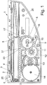
- a damping device 1 comprises a driver 2, which can be coupled with a movable furniture part, such as a cabinet door.
- a recess 25 is formed on the driver 2, in which a pin of a furniture part can be inserted.
- the driver 2 is guided over a pin 3 along a path 4, which has an angled end 5.
- the driver 2 is rotatably mounted on a boom 6, which is connected to a rack 7.
- the rack 7 is in engagement with a gear 8, which is part of a transmission, and is rotatably supported by an axle 9.
- the axis 9 is held in an elongated receptacle 10, so that the axis 9 in the receptacle 10 both rotated and can be moved.
- the gear 8 meshes with a smaller diameter adjacent gear 11, which in turn is connected to a larger diameter gear 12.
- the gear 12 is in engagement with a gear 13, which also has a smaller and a larger gear, which is in engagement with a damper 14.
- the damper 14 is designed as a rotary damper, preferably as an eddy current brake, wherein other dampers, such as fluid damper can be used.
- a control 15 in the form of a protruding pin on the gear 8 is formed, along a first cam guide 16 for the starting position of the driver 2 and a second cam guide 17 for the end position of the driver 2 movable is.
- the gear 8 is positioned in a predetermined orientation relative to the rack 7, wherein for the sake of assembly, a cut tooth base 30 is provided on the rack 7, which is in engagement with a cut flat tooth 31 on the gear 8.
- This tooth base 30 or tooth 31 form markings to set the gear 8 in a predetermined position on the rack 7, so that the position of the control element 15 is defined relative to the driver 2.
- FIG. 1 the starting position of the driver 2 is shown, in which a movable furniture part, such as a cabinet door in the closed position.
- a movable furniture part such as a cabinet door in the closed position.
- the rack 7 moves with and acts on the gear 8, which is moved with its axis 9 within the receptacle 10 and thus disengaged from the adjacent gear 11 passes.
- This movement of the axis 9 for disengaging the gear 8 of the freewheel is optionally supported by the control element 15 and the cam guide 16.
- the cam guide 16 may be formed integrally with a housing 20 or is fixed thereto.
- FIG. 3 the damping device 1 is shown in a position shortly before the disengagement of the furniture part of the driver 2.
- the driver 2 has moved along the track 4 to the angled portion 5. Since the rack 7 meshes with the gear 8 of the freewheel, the gear 8 is dependent on the position of the driver 2 in a predetermined angular position. Shortly before reaching the end position of the driver 2, the control 15 begins to abut the cam guide 17 for engaging the gear 8 of the freewheel.
- two teeth 32 of the gear 8 are provided with a chamfer 33, which facilitate the engagement of the gear 8 with the adjacent gear 11.
- the chamfers 33 give the teeth 32 an asymmetrical shape and ensure that the gears 8 and 11 can not get caught or jammed together.
- the remaining teeth of the gear 8 also have chamfers 34 at the tooth tip, which, however, are oriented in a different direction.
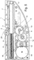
- FIG. 4 a position of the driver 2 is shown in which the pin 3 is guided at the angled portion 5 down and thus the driver 2 is pivoted.
- the cam guide 17 begins, so on the Actuate control element 15 of the gear 8, that this is moved along the axis 9 in the receptacle 10.
- the operation of engaging the gear 8 with the adjacent gear 11 begins.
- one or more teeth 32 adjacent to the gear 11 in the position of engagement are configured with a particular shape that facilitates engagement.
- a tooth flank is bevelled, so that accidental jamming of the opposing teeth is reliably avoided.
- the switching operation of the gear 8 of the freewheel can be realized with only a few components in a simple manner, with the predetermined position of the gear 8 relative to the driver 2 an exact switching is possible. In particular, loud noises can be avoided by a precise switching.
- the gear 8 has a protruding axis 9 which can be inserted into the receptacle 10. Further, on a tooth of the gear, a protruding in the axial direction control element 15 is formed in the form of a driver, which can be brought into engagement with the cam guides 16 and 17.
- FIG. 8 shows the housing of the damping device 1, which may be made of plastic as an injection molded part. Integral with the housing are formed by a wall protruding webs for forming the receptacle 10 and the cam guide 16 and 17. Furthermore, annular receptacles 41 and 42 are formed on the wall of the housing, which serve as axle mounts for gears. At a portion of the housing, a pot 40 is formed, in which the disc-shaped rotary damper 14 can be inserted.
- the positive guidance is realized by a control element 15 on the gear 8 and a cam guide 17 and 16 respectively. It is of course possible to realize the positive guidance of the gear 8 of the freewheel by other means, for example, a cam guide can also be used to move the axle 9.
- a cam guide can also be used to move the axle 9.
- the curved guides 16 and 17 formed in two sections can also be connected to one another and formed in one piece.
Landscapes
- Engineering & Computer Science (AREA)
- Mechanical Engineering (AREA)
- Gears, Cams (AREA)
- Transmission Devices (AREA)
Description
- Die vorliegende Erfindung betrifft eine Dämpfungseinrichtung für bewegbare Möbelteile, insbesondere für Schranktüren, mit einem Mitnehmer, der mit einem bewegbaren Möbelteil koppelbar ist und der über ein Getriebe mit einem Dämpfer gekoppelt ist, wobei das Getriebe ein Zahnrad eines Freilaufes aufweist, das mit einem benachbarten Zahnrad ein- und auskuppelbar ist.
- Die
WO 2006/114352 offenbart eine Dämpfungseinrichtung für bewegbare Möbelteile, bei der ein Mitnehmer mit einer Zahnstange gekoppelt ist, die ein Zahnrad eines Freilaufs antreibt. Das Zahnrad des Freilaufs ist in einer ersten Position mit einem Getriebe und einer Wirbelstrombremse verbunden und in einer zweiten Position von dem Getriebe ausgekuppelt, so dass eine Dämpfungswirkung nur in eine Bewegungsrichtung vorhanden ist. Das Zahnrad des Freilaufs ist dabei über eine Feder in die eingekuppelte Position vorgespannt, wobei die Feder über einen Vorsprung beaufschlagbar ist. Diese Konstruktion besitzt den Nachteil, dass für einen Schaltvorgang vergleichsweise viele Bauteile notwendig sind und aufgrund von Herstellungstoleranzen und Ungenauigkeiten das Schaltverhalten nicht besonders exakt ausgestaltet ist. Dabei verursacht die Feder als Schaltelement im Betrieb Geräusche. - Es ist daher Aufgabe der vorliegenden Erfindung eine Dämpfungseinrichtung für bewegbare Möbelteile zu schaffen, bei der das Schaltverhalten eines Zahnrades des Freilaufs verbessert ist.
- Diese Aufgabe wird mit einer Dämpfungseinrichtung mit den Merkmalen des Anspruches 1 gelöst.
- Erfindungsgemäß ist eine Zwangsführung für das Zahnrad des Freilaufs vorgesehen, um dieses bei einer vorbestimmten Position des Mitnehmers mit dem benachbarten Zahnrad ein- oder auszukuppeln. Dadurch wird erreicht, dass der Schaltvorgang des Zahnrades genauer ausgeführt werden kann, weil die Zwangsführung abhängig von der Position des Mitnehmers den Schaltvorgang realisiert.
- Die Zwangsführung umfasst eine Kurvenführung, mittels der das Zahnrad des Freilaufs bei einer Bewegung des Mitnehmers verschiebbar ist. Eine solche Kurvenführung kann aus wenigen Bauteilen aufgebaut sein und ist verschleißunanfällig. Ferner kann die Genauigkeit der Schaltbewegung des Zahnrades deutlich verbessert werden.
- Vorzugsweise ist mittels der Zwangsführung das Zahnrad des Freilaufs in einer Endposition des Mitnehmers mit dem benachbarten Zahnrad eingekuppelt. In dieser Endposition ist die Dämpfungseinrichtung gespannt und ein bewegbares Möbelteil meist von dem Mitnehmer entkoppelt. Durch eine Bewegung des Möbelteils zu dem Mitnehmer hin wird dann dieser betätigt und in eine Ausgangsposition zurückbewegt, wobei der Verfahrweg des Dämpfers dann gedämpft verläuft. Dabei ist es möglich, dass die Zwangsführung sowohl in der Ausgangsposition als auch in der Endposition des Mitnehmers wirksam ist. Alternativ kann die Zwangsführung auch nur in der Endposition eingesetzt werden, da in dieser Position die größeren mechanischen Belastungen auftreten.
- Gemäß einer weiteren Ausgestaltung der Erfindung weist das Zahnrad des Freilaufs eine Achse auf, die zwischen einer eingekuppelten und einer ausgekuppelten Position des Zahnrads verschiebbar ist. Die Achse kann dabei in einer Aufnahme geführt sein, so dass der Verschiebeweg der Achse genau festgelegt ist.
- Für eine einfache Ausgestaltung der Zwangsführung kann diese ein Steuerelement aufweisen, das an dem Zahnrad des Freilaufs festgelegt ist. Das Steuerelement kann dabei als Vorsprung an dem Zahnrad ausgebildet sein, der zumindest bereichsweise entlang einer Kurvenführung bewegbar ist. Die Kurvenführung kann dabei integral mit dem Gehäuse der Dämpfungseinrichtung oder in dem Gehäuse festgelegt sein.
- Gemäß einer weiteren Ausgestaltung der Erfindung ist die Zwangsführung in Endstellung des Mitnehmers wirksam um das Zahnrad des Freilaufs ein- bzw. auszukuppeln. Denn ausgehend von der Ausgangsposition wird durch die Zwangsführung sichergestellt, dass zunächst das Zahnrad ausgekuppelt ist und der Freilauf wirksam ist, um ein leichtgängiges Verschieben des Mitnehmers in die Endstellung zu ermöglichen. Sobald der Mitnehmer aus der Endstellung bewegt wird, muss durch das Einkuppeln in der Endstellung der Dämpfer wirksam werden, um ein Verschieben des Mitnehmers mit Dämpfungswirkung zu erreichen.
- Damit die Position des Mitnehmers relativ zu dem Zahnrad des Freilaufs exakt vorgegeben ist, kann der Mitnehmer mit einer Zahnstange gekoppelt sein, die in Eingriff mit dem Zahnrad des Freilaufs steht. Dadurch werden der Ausgangs- und der Endposition des Mitnehmers eine vorbestimmte Winkelposition des Zahnrades zugeordnet. Dabei kann eine Markierung an der Zahnstange und dem Zahnrad des Freilaufs zur Ausrichtung des Zahnrades bzw. der Zahnstange bei der Montage vorgesehen sein, damit eine Fehlmontage vermieden wird.
- Um das Ein- und Auskuppeln zu erleichtern, kann mindestens ein Zahn an dem Zahnrad des Freilaufs eine von den anderen Zähnen modifizierte Form aufweisen. Aufgrund einer vorgegebenen Winkelposition beim Einkuppeln des Zahnrades des Freilaufs in der Endstellung kann der bzw. können die Zähne lokalisiert werden, die mit den Zähnen des benachbarten Zahnrades in Eingriff gelangen. Vorzugsweise weisen zwei Zähne an dem Zahnrad an einer Zahnflanke eine Abschrägung auf, um das Einkuppeln zu erleichtern.
- Die Erfindung wird nachfolgend anhand eines Ausführungsbeispiels mit Bezug auf die beigefügten Zeichnungen näher erläutert. Es zeigen:
- Figur 1
- eine Ansicht eines Ausführungsbeispiels einer erfindungsgemäßen Dämpfungseinrichtung in einer Ausgangsposition;
- Figuren 2 bis 5
- mehrere Ansichten der Dämpfungseinrichtung der
Figur 1 in unterschiedlichen Positionen des Mitnehmers; - Figur 6
- eine Detailansicht der Dämpfungseinrichtung in einer Schaltposition;
- Figur 7
- eine perspektivische Ansicht eines Zahnrades der Dämpfungseinrichtung, und
- Figur 8
- eine perspektivische Ansicht des Gehäuses der Dämpfungseinrichtung.
- Eine Dämpfungseinrichtung 1 umfasst einen Mitnehmer 2, der mit einem bewegbaren Möbelteil, wie einer Schranktür koppelbar ist. Hierfür ist an dem Mitnehmer 2 eine Aussparung 25 ausgebildet, in die ein Stift eines Möbelteils einfügbar ist. Der Mitnehmer 2 ist über einen Stift 3 entlang einer Bahn 4 geführt, die ein abgewinkeltes Ende 5 aufweist. Der Mitnehmer 2 ist dabei drehbar an einem Ausleger 6 gelagert, der mit einer Zahnstange 7 verbunden ist.
- Die Zahnstange 7 steht mit einem Zahnrad 8 in Eingriff, das Bestandteil eines Getriebes ist, und über eine Achse 9 drehbar gelagert ist. Die Achse 9 ist dabei in einer länglichen Aufnahme 10 gehalten, so dass die Achse 9 in der Aufnahme 10 sowohl gedreht als auch verschoben werden kann.
- Das Zahnrad 8 kämmt mit einem benachbarten Zahnrad 11 mit kleinerem Durchmesser, das wiederum mit einem Zahnrad 12 mit größerem Durchmesser verbunden ist. Das Zahnrad 12 steht in Eingriff mit einem Zahnrad 13, das ebenfalls ein kleineres und ein größeres Zahnrad aufweist, das in Eingriff mit einem Dämpfer 14 steht. Der Dämpfer 14 ist als Drehdämpfer ausgebildet, vorzugsweise als Wirbelstrombremse, wobei auch andere Dämpfer, wie Fluiddämpfer eingesetzt werden können.
- Um das Zahnrad 8 bei einem Schaltvorgang exakt zu bewegen, ist ein Steuerelement 15 in Form eines hervorstehenden Zapfens an dem Zahnrad 8 ausgebildet, der entlang einer ersten Kurvenführung 16 für die Ausgangsposition des Mitnehmers 2 und einer zweiten Kurvenführung 17 für die Endposition des Mitnehmers 2 bewegbar ist. Dabei ist das Zahnrad 8 in einer vorbestimmten Ausrichtung relativ zu der Zahnstange 7 positioniert, wobei zur Erleichterung der Montage ein abgeschnittener Zahngrund 30 an der Zahnstange 7 vorgesehen ist, der in Eingriff mit einem abgeschnittenen Flachzahn 31 an dem Zahnrad 8 steht. Dieser Zahngrund 30 bzw. Zahn 31 bilden Markierungen aus, um das Zahnrad 8 in einer vorbestimmten Position an der Zahnstange 7 festzulegen, so dass auch die Position des Steuerelementes 15 relativ zu dem Mitnehmer 2 definiert ist.
- In
Figur 1 ist die Ausgangsposition des Mitnehmers 2 gezeigt, in dem ein bewegbares Möbelteil, wie eine Schranktür in der geschlossenen Position ist. Wird der Mitnehmer 2 beim Öffnen der Schranktür bewegt (Figur 2 ), bewegt sich die Zahnstange 7 mit und wirkt auf das Zahnrad 8 ein, das mit seiner Achse 9 verschoben wird innerhalb der Aufnahme 10 und somit außer Eingriff mit dem benachbarten Zahnrad 11 gelangt. Diese Bewegung der Achse 9 zum Auskuppeln des Zahnrades 8 des Freilaufs wird gegebenenfalls durch das Steuerelement 15 und die Kurvenführung 16 unterstützt. Die Kurvenführung 16 kann dabei integral mit einem Gehäuse 20 ausgebildet sein oder ist daran festgelegt. - In
Figur 3 ist die Dämpfungseinrichtung 1 in einer Position kurz vor dem Auskuppeln des Möbelteils von dem Mitnehmer 2 gezeigt. Der Mitnehmer 2 hat sich entlang der Bahn 4 bis vor den abgewinkelten Abschnitt 5 bewegt. Da die Zahnstange 7 mit dem Zahnrad 8 des Freilaufs kämmt, befindet sich das Zahnrad 8 abhängig von der Position des Mitnehmers 2 in einer vorbestimmten Winkelposition. Kurz vor dem Erreichen der Endstellung des Mitnehmers 2 fängt das Steuerelement 15 an an der Kurvenführung 17 zum Einkuppeln des Zahnrads 8 des Freilaufs anzuliegen. - Wie aus der vergrößerten Darstellung der
Figur 3A erkennbar ist sind zwei Zähne 32 des Zahnrads 8 mit einer Abschrägung 33 versehen, die das Einkuppeln des Zahnrads 8 mit dem benachbarten Zahnrad 11 erleichtern. Die Abschrägungen 33 geben den Zähnen 32 eine asymmetrische Form und sorgen dafür, dass die Zahnräder 8 und 11 nicht aneinander verhaken bzw. verklemmen können. Die übrigen Zähne des Zahnrades 8 weisen ebenfalls Abschrägungen 34 an der Zahnspitze auf, die allerdings in eine andere Richtung orientiert sind. - In
Figur 4 ist eine Position des Mitnehmers 2 gezeigt, in der der Stift 3 an dem abgewinkelten Abschnitt 5 nach unten geführt wird und somit der Mitnehmer 2 verschwenkt wird. In dieser Position fängt die Kurvenführung 17 an, derart auf das Steuerelement 15 des Zahnrades 8 einzuwirken, dass dieses entlang der Achse 9 in der Aufnahme 10 verschoben wird. Dadurch beginnt der Vorgang des Einkuppelns des Zahnrades 8 mit dem benachbarten Zahnrad 11. - Da die Position des Einkuppelns des Zahnrades 8 exakt vorbestimmt ist, werden ein oder mehrere Zähne 32, die in der Position des Einkuppelns benachbart zu dem Zahnrad 11 liegen, mit einer besonderen Form ausgestaltet, die das Einkuppeln erleichtert. Bei dem Zahn 32 ist eine Zahnflanke abgeschrägt ausgebildet, so dass ein versehentliches Verklemmen der sich gegenüberliegenden Zähne sicher vermieden wird.
- Aufgrund der Zwangsführung des Zahnrades 8 durch das Steuerelement 15 und die Kurvenführung 17 wird die Achse 9 soweit in der Aufnahme 10 verschoben worden ist, dass bereits ein leichter Eingriff mit dem benachbarten Zahnrad 11 stattgefunden hat.
- In den
Figur 5 und6 ist die Endposition des Mitnehmers 2 gezeigt, der nun mit dem Stift 3 bis zum Ende des abgewinkelten Abschnittes 5 verfahren ist. Dadurch wurde der Mitnehmer 2 verschwenkt und ein mit dem Möbelteil verbundenes Element aus der Aufnahme 25 herausbewegt. In dieser Position wurde aufgrund der Zwangsführung des Zahnrads 8 mittels der Kurvenführung 17 und dem Steuerelement 15 die Achse 9 in die vollständig eingekuppelte Position innerhalb der Aufnahme 10 bewegt und die Zähne des Zahnrades 8 stehen in Eingriff mit dem Zähnen des benachbarten Zahnrades 11. Eine zwischen dem Gehäuse 20 und der Zahnstange 7 gespannte Feder 18 ist gespannt und der Mitnehmer 2 ist verriegelt. Sobald der Mitnehmer 2 durch das in die geschlossene Position sich bewegende Möbelteil entriegelt wird, zieht die Feder 18 die Zahnstange 7 in die Ausgangsposition. Aufgrund der Kraft der Zahnstange 7 auf das Zahnrad 8 wird dieses inFigur 6 nach links gedrückt und kann allerdings aufgrund der Aufnahme 10 nicht weiter verschoben werden, weshalb eine Drehbewegung des Zahnrades 8 eingeleitet wird. Diese Drehbewegung setzt sich fort auf das Zahnrad 11 und die anderen Zahnräder 12 und 13 des Getriebes. Durch das Getriebe wird der Dämpfer 14 betätigt, der dafür sorgt, dass der Schließvorgang des Möbelteils gedämpft mit der gewünschten Geschwindigkeit erfolgt. Wenn der Mitnehmer 2 wieder in die Ausgangsposition kommt, wird wieder die inFigur 1 gezeigte Position erreicht. - Der Schaltvorgang des Zahnrades 8 des Freilaufs kann mit nur wenigen Bauteilen auf einfache Weise realisiert werden, wobei durch die vorbestimmte Position des Zahnrades 8 relativ zu dem Mitnehmer 2 ein exaktes Schalten möglich ist. Insbesondere können laute Geräusche durch ein exaktes Schalten vermieden werden.
- Wie aus
Figur 7 erkennbar ist, weist das Zahnrad 8 eine hervorstehende Achse 9 auf, die in die Aufnahme 10 einfügbar ist. Ferner ist an einem Zahn des Zahnrades ein in axiale Richtung hervorstehendes Steuerelement 15 in Form eines Mitnehmers ausgebildet, der in Eingriff mit den Kurvenführungen 16 und 17 gebracht werden kann. - Die
Figur 8 zeigt das Gehäuse der Dämpfungseinrichtung 1, das als Spritzgussteil aus Kunststoff hergestellt sein kann. Integral mit dem Gehäuse sind von einer Wand hervorstehende Stege zur Ausbildung der Aufnahme 10 und für die Kurvenführung 16 und 17 ausgebildet. Ferner sind an der Wand des Gehäuses ringförmige Aufnahmen 41 und 42 ausgebildet, die als Achsaufnahmen für Zahnräder dienen. An einem Abschnitt des Gehäuses ist ein Topf 40 ausgebildet, in den der scheibenförmige Drehdämpfer 14 einfügbar ist. - In dem dargestellten Ausführungsbeispiel ist die Zwangsführung durch ein Steuerelement 15 an dem Zahnrad 8 und eine Kurvenführung 17 bzw. 16 realisiert. es ist natürlich möglich, die Zwangsführung des Zahnrades 8 des Freilaufes auch mit anderen Mitteln zu realisieren, beispielsweise kann eine Kurvenführung auch zum Verschieben der Achse 9 eingesetzt werden. Zudem können die in zwei Abschnitten ausgebildeten Kurvenführungen 16 und 17 auch miteinander verbunden und einteilig ausgebildet sein.
Claims (10)
- Dämpfungseinrichtung (1) für bewegbare Möbelteile, insbesondere für Schranktüren, mit einem Mitnehmer (2), der mit einem bewegbaren Möbelteil koppelbar ist, und der über ein Getriebe (8, 11, 12, 13) mit einem Dämpfer (14) gekoppelt ist, wobei das Getriebe ein Zahnrad (8) eines Freilaufs aufweist, das mit einem benachbarten Zahnrad (11) ein- und auskuppelbar ist, wobei eine Zwangsführung (15, 16, 17) für das Zahnrad (8) des Freilaufs vorgesehen ist, um dieses bei einer vorbestimmten Position des Mitnehmers (2) mit dem benachbarten Zahnrad (11) ein- oder auszukuppeln, dadurch gekennzeichnet, dass die Zwangsführung eine Kurvenführung (15, 16, 17) umfasst, mittels der das Zahnrad (8) des Freilaufs bei einer Bewegung des Mitnehmers (2) verschiebbar ist.
- Dämpfungseinrichtung nach Anspruch 1, dadurch gekennzeichnet, dass mittels der Zwangsführung (15, 17) das Zahnrad (8) des Freilaufs in einer Endposition des Mitnehmers (2) mit dem benachbarten Zahnrad (11) eingekuppelt ist.
- Dämpfungseinrichtung nach Anspruch 1 oder 2, dadurch gekennzeichnet, dass das Zahnrad (8) des Freilaufs eine Achse (9) aufweist, die zwischen einer eingekuppelten und einer ausgekuppelten Position des Zahnrades (8) verschiebbar ist.
- Dämpfungseinrichtung nach einem der Ansprüche 1 bis 3, dadurch gekennzeichnet, dass die Zwangsführung ein Steuerelement (15) aufweist, das an dem Zahnrad (8) des Freilaufs festgelegt ist.
- Dämpfungseinrichtung nach Anspruch 4, dadurch gekennzeichnet, dass das Steuerelement (15) als Vorsprung an dem Zahnrad (8) ausgebildet ist, der zumindest bereichsweise entlang einer Kurvenführung (16, 17) bewegbar ist.
- Dämpfungseinrichtung nach einem der Ansprüche 1 bis 5, dadurch gekennzeichnet, dass die Zwangsführung in Endstellungen des Mitnehmers (2) wirksam ist, um das Zahnrad (8) des Freilaufs ein- bzw. auszukuppeln.
- Dämpfungseinrichtung nach einem der Ansprüche 1 bis 6, dadurch gekennzeichnet, dass der Mitnehmer (2) mit einer Zahnstange (7) gekoppelt ist, die mit dem Zahnrad (8) des Freilaufs in Eingriff steht.
- Dämpfungseinrichtung nach einem der Ansprüche 1 bis 7, dadurch gekennzeichnet, dass mindestens ein Zahn (32) an dem Zahnrad (8) des Freilaufs eine von den anderen Zähnen modifizierte Form zum Erleichtern des Ein- und Auskuppelns aufweist.
- Dämpfungseinrichtung nach Anspruch 8, dadurch gekennzeichnet, dass zwei Zähne an dem Zahnrad (8) an einer Zahnflanke eine Abschrägung aufweisen.
- Dämpfungseinrichtung nach einem der Ansprüche 1 bis 9, dadurch gekennzeichnet, dass eine Markierung (30, 31) an der Zahnstange (7) und dem Zahnrad (8) des Freilaufs zur Ausrichtung des Zahnrades (8) bzw. der Zahnstange (7) bei der Montage vorgesehen ist.
Priority Applications (1)
| Application Number | Priority Date | Filing Date | Title |
|---|---|---|---|
| SI200831832T SI2082667T1 (sl) | 2008-01-22 | 2008-11-18 | Dušilna naprava za premične dele pohištva |
Applications Claiming Priority (1)
| Application Number | Priority Date | Filing Date | Title |
|---|---|---|---|
| DE202008000931U DE202008000931U1 (de) | 2008-01-22 | 2008-01-22 | Dämpfungseinrichtung für bewegbare Möbelteile |
Publications (2)
| Publication Number | Publication Date |
|---|---|
| EP2082667A1 EP2082667A1 (de) | 2009-07-29 |
| EP2082667B1 true EP2082667B1 (de) | 2017-04-12 |
Family
ID=40602245
Family Applications (1)
| Application Number | Title | Priority Date | Filing Date |
|---|---|---|---|
| EP08169374.9A Not-in-force EP2082667B1 (de) | 2008-01-22 | 2008-11-18 | Dämpfungseinrichtung für bewegbare Möbelteile |
Country Status (5)
| Country | Link |
|---|---|
| EP (1) | EP2082667B1 (de) |
| DE (1) | DE202008000931U1 (de) |
| ES (1) | ES2630157T3 (de) |
| PL (1) | PL2082667T3 (de) |
| SI (1) | SI2082667T1 (de) |
Families Citing this family (1)
| Publication number | Priority date | Publication date | Assignee | Title |
|---|---|---|---|---|
| AT509923B1 (de) * | 2010-06-01 | 2013-12-15 | Blum Gmbh Julius | Einzugsvorrichtung zum einziehen eines bewegbar gelagerten möbelteiles |
Family Cites Families (5)
| Publication number | Priority date | Publication date | Assignee | Title |
|---|---|---|---|---|
| US5690194A (en) * | 1995-10-30 | 1997-11-25 | Illinois Tool Works Inc. | One-way pivoting gear damper |
| US6848759B2 (en) * | 2002-04-03 | 2005-02-01 | Illinois Tool Works Inc. | Self-closing slide mechanism with damping |
| GB0328262D0 (en) * | 2003-12-05 | 2004-01-07 | Titus Int Plc | Improvements in movement controls |
| DE202005006931U1 (de) | 2005-04-28 | 2006-08-31 | Hettich-Heinze Gmbh & Co. Kg | Dämpfungseinrichtung für bewegbare Möbelteile |
| DE102006059585A1 (de) * | 2006-12-16 | 2008-06-19 | Huf Hülsbeck & Fürst Gmbh & Co. Kg | Vorrichtung mit einem abbremsbaren beweglichen Glied |
-
2008
- 2008-01-22 DE DE202008000931U patent/DE202008000931U1/de not_active Expired - Lifetime
- 2008-11-18 SI SI200831832T patent/SI2082667T1/sl unknown
- 2008-11-18 PL PL08169374T patent/PL2082667T3/pl unknown
- 2008-11-18 EP EP08169374.9A patent/EP2082667B1/de not_active Not-in-force
- 2008-11-18 ES ES08169374.9T patent/ES2630157T3/es active Active
Non-Patent Citations (1)
| Title |
|---|
| None * |
Also Published As
| Publication number | Publication date |
|---|---|
| DE202008000931U1 (de) | 2009-05-28 |
| SI2082667T1 (sl) | 2017-08-31 |
| ES2630157T3 (es) | 2017-08-18 |
| PL2082667T3 (pl) | 2017-09-29 |
| EP2082667A1 (de) | 2009-07-29 |
Similar Documents
| Publication | Publication Date | Title |
|---|---|---|
| EP2174571B1 (de) | Öffnungsvorrichtung für eine Ausziehführung und Rastmechanismus | |
| DE102004036369B4 (de) | Steuertrommelanordnung für ein Kraftfahrzeug-Wechselgetriebe | |
| EP2931998B1 (de) | Kraftfahrzeugtürschloss | |
| EP2208440A1 (de) | Rastbeschlag und Auszugsführung | |
| AT514666B1 (de) | Führungsvorrichtung für bewegbare Möbelteile | |
| DE102016118687A1 (de) | Spindeleinheit | |
| WO2014117188A1 (de) | Möbelbeschlag | |
| EP3274612B1 (de) | Stelleinheit für einen zuziehantrieb für ein kraftfahrzeugschloss | |
| EP2526825B1 (de) | Einzugvorrichtung | |
| DE10300876A1 (de) | Gleitstück für Türschliesser oder Drehflügelantriebe | |
| DE102009020994B4 (de) | Einzugvorrichtung | |
| DE2921343C2 (de) | Reißverschlußschieber mit Sperrschloß | |
| EP1136728B1 (de) | Stufenwechselgetriebe | |
| DE10029620B4 (de) | Schaltwelle für ein Schaltgetriebe und Verfahren zu ihrer Herstellung | |
| EP2082667A1 (de) | Dämpfungseinrichtung für bewegbare Möbelteile | |
| DE102014202886A1 (de) | Schaltanordnung für ein Getriebe | |
| DE102013105366A1 (de) | Kupplungsvorrichtung sowie Klappenvorrichtung mit einer derartigen Kupplungsvorrichtung | |
| DE102006012726A1 (de) | Anschlagpufferanordnung | |
| WO2013020541A1 (de) | Parksperre | |
| DE102014107767B3 (de) | Schaltwellenmodul zum Schalten von Gängen in einem Schaltgetriebe | |
| DE102018119638A1 (de) | Fahrzeuginnenraumkomponente zur Anbringung an einer Fahrzeugkarosserie | |
| DE102013210516B3 (de) | Einzugsvorrichtung für einen Flügel einer Tür oder eines Fensters | |
| EP2317629B1 (de) | Stellantrieb einer Komponente eines Kraftfahrzeugs | |
| DE102013219943A1 (de) | Schaltanordnung für ein Kraftfahrzeug-Zahnräderwechselgetriebe | |
| DE202009006855U1 (de) | Einzugvorrichtung |
Legal Events
| Date | Code | Title | Description |
|---|---|---|---|
| PUAI | Public reference made under article 153(3) epc to a published international application that has entered the european phase |
Free format text: ORIGINAL CODE: 0009012 |
|
| AK | Designated contracting states |
Kind code of ref document: A1 Designated state(s): AT BE BG CH CY CZ DE DK EE ES FI FR GB GR HR HU IE IS IT LI LT LU LV MC MT NL NO PL PT RO SE SI SK TR |
|
| AX | Request for extension of the european patent |
Extension state: AL BA MK RS |
|
| 17P | Request for examination filed |
Effective date: 20090813 |
|
| 17Q | First examination report despatched |
Effective date: 20090914 |
|
| AKX | Designation fees paid |
Designated state(s): AT BE BG CH CY CZ DE DK EE ES FI FR GB GR HR HU IE IS IT LI LT LU LV MC MT NL NO PL PT RO SE SI SK TR |
|
| RAP1 | Party data changed (applicant data changed or rights of an application transferred) |
Owner name: HETTICH-HEINZE GMBH & CO. KG |
|
| GRAP | Despatch of communication of intention to grant a patent |
Free format text: ORIGINAL CODE: EPIDOSNIGR1 |
|
| INTG | Intention to grant announced |
Effective date: 20160803 |
|
| GRAS | Grant fee paid |
Free format text: ORIGINAL CODE: EPIDOSNIGR3 |
|
| STAA | Information on the status of an ep patent application or granted ep patent |
Free format text: STATUS: GRANT OF PATENT IS INTENDED |
|
| REG | Reference to a national code |
Ref country code: DE Ref legal event code: R079 Ref document number: 502008015207 Country of ref document: DE Free format text: PREVIOUS MAIN CLASS: A47B0088040000 Ipc: A47B0088467000 |
|
| GRAA | (expected) grant |
Free format text: ORIGINAL CODE: 0009210 |
|
| STAA | Information on the status of an ep patent application or granted ep patent |
Free format text: STATUS: THE PATENT HAS BEEN GRANTED |
|
| AK | Designated contracting states |
Kind code of ref document: B1 Designated state(s): AT BE BG CH CY CZ DE DK EE ES FI FR GB GR HR HU IE IS IT LI LT LU LV MC MT NL NO PL PT RO SE SI SK TR |
|
| REG | Reference to a national code |
Ref country code: GB Ref legal event code: FG4D Free format text: NOT ENGLISH |
|
| RIC1 | Information provided on ipc code assigned before grant |
Ipc: A47B 88/467 20170101AFI20170308BHEP |
|
| REG | Reference to a national code |
Ref country code: CH Ref legal event code: EP |
|
| REG | Reference to a national code |
Ref country code: IE Ref legal event code: FG4D Free format text: LANGUAGE OF EP DOCUMENT: GERMAN |
|
| REG | Reference to a national code |
Ref country code: AT Ref legal event code: REF Ref document number: 883023 Country of ref document: AT Kind code of ref document: T Effective date: 20170515 Ref country code: CH Ref legal event code: NV Representative=s name: ISLER AND PEDRAZZINI AG, CH |
|
| REG | Reference to a national code |
Ref country code: DE Ref legal event code: R096 Ref document number: 502008015207 Country of ref document: DE |
|
| REG | Reference to a national code |
Ref country code: ES Ref legal event code: FG2A Ref document number: 2630157 Country of ref document: ES Kind code of ref document: T3 Effective date: 20170818 Ref country code: NL Ref legal event code: MP Effective date: 20170412 |
|
| REG | Reference to a national code |
Ref country code: LT Ref legal event code: MG4D |
|
| PG25 | Lapsed in a contracting state [announced via postgrant information from national office to epo] |
Ref country code: NL Free format text: LAPSE BECAUSE OF FAILURE TO SUBMIT A TRANSLATION OF THE DESCRIPTION OR TO PAY THE FEE WITHIN THE PRESCRIBED TIME-LIMIT Effective date: 20170412 |
|
| PG25 | Lapsed in a contracting state [announced via postgrant information from national office to epo] |
Ref country code: NO Free format text: LAPSE BECAUSE OF FAILURE TO SUBMIT A TRANSLATION OF THE DESCRIPTION OR TO PAY THE FEE WITHIN THE PRESCRIBED TIME-LIMIT Effective date: 20170712 Ref country code: FI Free format text: LAPSE BECAUSE OF FAILURE TO SUBMIT A TRANSLATION OF THE DESCRIPTION OR TO PAY THE FEE WITHIN THE PRESCRIBED TIME-LIMIT Effective date: 20170412 Ref country code: LT Free format text: LAPSE BECAUSE OF FAILURE TO SUBMIT A TRANSLATION OF THE DESCRIPTION OR TO PAY THE FEE WITHIN THE PRESCRIBED TIME-LIMIT Effective date: 20170412 Ref country code: GR Free format text: LAPSE BECAUSE OF FAILURE TO SUBMIT A TRANSLATION OF THE DESCRIPTION OR TO PAY THE FEE WITHIN THE PRESCRIBED TIME-LIMIT Effective date: 20170713 Ref country code: HR Free format text: LAPSE BECAUSE OF FAILURE TO SUBMIT A TRANSLATION OF THE DESCRIPTION OR TO PAY THE FEE WITHIN THE PRESCRIBED TIME-LIMIT Effective date: 20170412 |
|
| PG25 | Lapsed in a contracting state [announced via postgrant information from national office to epo] |
Ref country code: BG Free format text: LAPSE BECAUSE OF FAILURE TO SUBMIT A TRANSLATION OF THE DESCRIPTION OR TO PAY THE FEE WITHIN THE PRESCRIBED TIME-LIMIT Effective date: 20170712 Ref country code: SE Free format text: LAPSE BECAUSE OF FAILURE TO SUBMIT A TRANSLATION OF THE DESCRIPTION OR TO PAY THE FEE WITHIN THE PRESCRIBED TIME-LIMIT Effective date: 20170412 Ref country code: LV Free format text: LAPSE BECAUSE OF FAILURE TO SUBMIT A TRANSLATION OF THE DESCRIPTION OR TO PAY THE FEE WITHIN THE PRESCRIBED TIME-LIMIT Effective date: 20170412 Ref country code: IS Free format text: LAPSE BECAUSE OF FAILURE TO SUBMIT A TRANSLATION OF THE DESCRIPTION OR TO PAY THE FEE WITHIN THE PRESCRIBED TIME-LIMIT Effective date: 20170812 |
|
| REG | Reference to a national code |
Ref country code: SK Ref legal event code: T3 Ref document number: E 24729 Country of ref document: SK |
|
| REG | Reference to a national code |
Ref country code: DE Ref legal event code: R097 Ref document number: 502008015207 Country of ref document: DE |
|
| PG25 | Lapsed in a contracting state [announced via postgrant information from national office to epo] |
Ref country code: RO Free format text: LAPSE BECAUSE OF FAILURE TO SUBMIT A TRANSLATION OF THE DESCRIPTION OR TO PAY THE FEE WITHIN THE PRESCRIBED TIME-LIMIT Effective date: 20170412 Ref country code: EE Free format text: LAPSE BECAUSE OF FAILURE TO SUBMIT A TRANSLATION OF THE DESCRIPTION OR TO PAY THE FEE WITHIN THE PRESCRIBED TIME-LIMIT Effective date: 20170412 Ref country code: DK Free format text: LAPSE BECAUSE OF FAILURE TO SUBMIT A TRANSLATION OF THE DESCRIPTION OR TO PAY THE FEE WITHIN THE PRESCRIBED TIME-LIMIT Effective date: 20170412 |
|
| PLBE | No opposition filed within time limit |
Free format text: ORIGINAL CODE: 0009261 |
|
| STAA | Information on the status of an ep patent application or granted ep patent |
Free format text: STATUS: NO OPPOSITION FILED WITHIN TIME LIMIT |
|
| 26N | No opposition filed |
Effective date: 20180115 |
|
| REG | Reference to a national code |
Ref country code: DE Ref legal event code: R084 Ref document number: 502008015207 Country of ref document: DE |
|
| PG25 | Lapsed in a contracting state [announced via postgrant information from national office to epo] |
Ref country code: MC Free format text: LAPSE BECAUSE OF FAILURE TO SUBMIT A TRANSLATION OF THE DESCRIPTION OR TO PAY THE FEE WITHIN THE PRESCRIBED TIME-LIMIT Effective date: 20170412 |
|
| GBPC | Gb: european patent ceased through non-payment of renewal fee |
Effective date: 20171118 |
|
| PG25 | Lapsed in a contracting state [announced via postgrant information from national office to epo] |
Ref country code: CZ Free format text: LAPSE BECAUSE OF NON-PAYMENT OF DUE FEES Effective date: 20171118 Ref country code: SK Free format text: LAPSE BECAUSE OF NON-PAYMENT OF DUE FEES Effective date: 20171118 Ref country code: CH Free format text: LAPSE BECAUSE OF NON-PAYMENT OF DUE FEES Effective date: 20171130 Ref country code: LI Free format text: LAPSE BECAUSE OF NON-PAYMENT OF DUE FEES Effective date: 20171130 |
|
| REG | Reference to a national code |
Ref country code: SK Ref legal event code: MM4A Ref document number: E 24729 Country of ref document: SK Effective date: 20171118 |
|
| PG25 | Lapsed in a contracting state [announced via postgrant information from national office to epo] |
Ref country code: SI Free format text: LAPSE BECAUSE OF NON-PAYMENT OF DUE FEES Effective date: 20171119 Ref country code: LU Free format text: LAPSE BECAUSE OF NON-PAYMENT OF DUE FEES Effective date: 20171118 |
|
| REG | Reference to a national code |
Ref country code: SI Ref legal event code: KO00 Effective date: 20180709 Ref country code: FR Ref legal event code: ST Effective date: 20180731 Ref country code: BE Ref legal event code: MM Effective date: 20171130 |
|
| REG | Reference to a national code |
Ref country code: IE Ref legal event code: MM4A |
|
| PG25 | Lapsed in a contracting state [announced via postgrant information from national office to epo] |
Ref country code: MT Free format text: LAPSE BECAUSE OF FAILURE TO SUBMIT A TRANSLATION OF THE DESCRIPTION OR TO PAY THE FEE WITHIN THE PRESCRIBED TIME-LIMIT Effective date: 20170412 |
|
| PG25 | Lapsed in a contracting state [announced via postgrant information from national office to epo] |
Ref country code: IT Free format text: LAPSE BECAUSE OF NON-PAYMENT OF DUE FEES Effective date: 20171118 Ref country code: FR Free format text: LAPSE BECAUSE OF NON-PAYMENT OF DUE FEES Effective date: 20171130 Ref country code: IE Free format text: LAPSE BECAUSE OF NON-PAYMENT OF DUE FEES Effective date: 20171118 |
|
| PG25 | Lapsed in a contracting state [announced via postgrant information from national office to epo] |
Ref country code: GB Free format text: LAPSE BECAUSE OF NON-PAYMENT OF DUE FEES Effective date: 20171118 Ref country code: BE Free format text: LAPSE BECAUSE OF NON-PAYMENT OF DUE FEES Effective date: 20171130 |
|
| REG | Reference to a national code |
Ref country code: AT Ref legal event code: MM01 Ref document number: 883023 Country of ref document: AT Kind code of ref document: T Effective date: 20171118 |
|
| PG25 | Lapsed in a contracting state [announced via postgrant information from national office to epo] |
Ref country code: AT Free format text: LAPSE BECAUSE OF NON-PAYMENT OF DUE FEES Effective date: 20171118 |
|
| PGFP | Annual fee paid to national office [announced via postgrant information from national office to epo] |
Ref country code: DE Payment date: 20181122 Year of fee payment: 11 |
|
| PG25 | Lapsed in a contracting state [announced via postgrant information from national office to epo] |
Ref country code: ES Free format text: LAPSE BECAUSE OF NON-PAYMENT OF DUE FEES Effective date: 20171119 |
|
| PG25 | Lapsed in a contracting state [announced via postgrant information from national office to epo] |
Ref country code: PL Free format text: LAPSE BECAUSE OF NON-PAYMENT OF DUE FEES Effective date: 20171118 |
|
| PG25 | Lapsed in a contracting state [announced via postgrant information from national office to epo] |
Ref country code: HU Free format text: LAPSE BECAUSE OF FAILURE TO SUBMIT A TRANSLATION OF THE DESCRIPTION OR TO PAY THE FEE WITHIN THE PRESCRIBED TIME-LIMIT; INVALID AB INITIO Effective date: 20081118 |
|
| PG25 | Lapsed in a contracting state [announced via postgrant information from national office to epo] |
Ref country code: CY Free format text: LAPSE BECAUSE OF NON-PAYMENT OF DUE FEES Effective date: 20170412 |
|
| PG25 | Lapsed in a contracting state [announced via postgrant information from national office to epo] |
Ref country code: PT Free format text: LAPSE BECAUSE OF FAILURE TO SUBMIT A TRANSLATION OF THE DESCRIPTION OR TO PAY THE FEE WITHIN THE PRESCRIBED TIME-LIMIT Effective date: 20170412 |
|
| REG | Reference to a national code |
Ref country code: DE Ref legal event code: R119 Ref document number: 502008015207 Country of ref document: DE |
|
| PG25 | Lapsed in a contracting state [announced via postgrant information from national office to epo] |
Ref country code: DE Free format text: LAPSE BECAUSE OF NON-PAYMENT OF DUE FEES Effective date: 20200603 |
|
| PG25 | Lapsed in a contracting state [announced via postgrant information from national office to epo] |
Ref country code: TR Free format text: LAPSE BECAUSE OF NON-PAYMENT OF DUE FEES Effective date: 20171118 |