EP2081070A2 - Microscope à phase polariscopique - Google Patents
Microscope à phase polariscopique Download PDFInfo
- Publication number
- EP2081070A2 EP2081070A2 EP09150365A EP09150365A EP2081070A2 EP 2081070 A2 EP2081070 A2 EP 2081070A2 EP 09150365 A EP09150365 A EP 09150365A EP 09150365 A EP09150365 A EP 09150365A EP 2081070 A2 EP2081070 A2 EP 2081070A2
- Authority
- EP
- European Patent Office
- Prior art keywords
- light beams
- phase
- polariscopic
- transform lens
- image generator
- Prior art date
- Legal status (The legal status is an assumption and is not a legal conclusion. Google has not performed a legal analysis and makes no representation as to the accuracy of the status listed.)
- Withdrawn
Links
Images

Classifications
-
- G—PHYSICS
- G02—OPTICS
- G02B—OPTICAL ELEMENTS, SYSTEMS OR APPARATUS
- G02B21/00—Microscopes
-
- G—PHYSICS
- G02—OPTICS
- G02B—OPTICAL ELEMENTS, SYSTEMS OR APPARATUS
- G02B21/00—Microscopes
- G02B21/0004—Microscopes specially adapted for specific applications
- G02B21/0092—Polarisation microscopes
-
- G—PHYSICS
- G02—OPTICS
- G02B—OPTICAL ELEMENTS, SYSTEMS OR APPARATUS
- G02B21/00—Microscopes
- G02B21/02—Objectives
-
- G—PHYSICS
- G02—OPTICS
- G02B—OPTICAL ELEMENTS, SYSTEMS OR APPARATUS
- G02B21/00—Microscopes
- G02B21/02—Objectives
- G02B21/04—Objectives involving mirrors
-
- G—PHYSICS
- G02—OPTICS
- G02B—OPTICAL ELEMENTS, SYSTEMS OR APPARATUS
- G02B21/00—Microscopes
- G02B21/06—Means for illuminating specimens
- G02B21/08—Condensers
- G02B21/14—Condensers affording illumination for phase-contrast observation
Definitions
- the present invention relates to a polariscopic phase microscope that can precisely observe a specimen, and more specifically, to a polariscopic phase microscope that can observe a structure and change of a physiological cell by using a phase contrast of light passing through components of the physiological cell.
- An optical microscope has been mainly used for the purpose of studying in medical and biological fields.
- a general optical microscope is configured to perform a method that directs light on a specimen, allows the light passing through the specimen to reflect a magnified real image on an objective lens, then re-magnifies the real image through an ocular lens, and observes the re-magnified real image.
- the general optical microscope observes the biological specimen such as the physiological cell, there is a problem in that it cannot completely perform the observation due to characteristic of the physiological cell, because it is transparent in a visible ray region. As a result, light is not absorbed other than a circumferential portion of the physiological cell. Therefore, microscopes have been developed to completely observe the biological specimen.
- phase-contrast microscope which is a microscope devised to be able to observe the biological specimen by using a difference in a refractive index unlike the general optical microscope, observes the biological specimen using a method of a phase contrast generated due to an interference phenomenon between a diffracted beam and a non-diffracted beam as a difference in light and shade.
- DIC microscope Differential interference microscope
- the Differential interference microscope is a microscope that can observe the biological specimen using the inference phenomenon of an optical wavelength with a method that overlaps an object light transmitting the specimen with the interference light separated from a light source by using a characteristic that allows an object to delay a light transmitting rate when light passes through the object.
- the method that observes the specimen using the phase contrast is an very useful method for a thin specimen.
- a cultured cell in a test dish is transparent in a visible wavelength and thus, can not be observed by the naked eye.
- the method using the phase contrast can observe the slight refractive index difference as described above by using the optical apparatus.
- the method transforms the optical path length difference of sample into different light intensities. While the light passes through the cytoplasm, the cell sap, and water, the light path is changed due to the difference in the refractive index.
- phase change This phenomenon is referred to as a phase change. That is, the light wave is still in an in-phase before the light completely enters the inside of the specimen, but after the light passes through the specimen, the phase of the light wave is changed. Therefore, the phase change depends on the type of materials in the path through which the light passes and the difference of the optical path occurring at the time of transmitting.
- the phase-contrast microscope and the differential interference microscope can observe the biological specimen such as the physiological cell, which cannot be observed by the existing optical microscope, by transforming the different phase information into different intensities of light due to the difference in the refractive index.
- the method using the phase contrast and differential phase contrast provides only qualitative phase information of the cell, there is a problem in that it has a limitation in accurately analyzing the biological specimen quantitatively. Therefore, apparatuses, which can provide quantitative information regarding the biological specimen, have been developed.
- the present invention proposes to solve the above problems. It is an object of the present invention to provide a polariscopic phase microscope that can acquire quantitative phase information having high transverse resolution and low noise that considers a change in a structure of a physiological cell.
- a polariscopic phase microscope comprising: an optical image generator that acquires images for a specimen to be observed; an object plane onto which light beams of the images acquired from the optical image generator are projected; a first transform lens that performs primary Fourier transformation on the light beams passing through the object plane; a ⁇ /4 wavelength plate that is positioned to be spaced at a focal distance of the first transform lens from the first transform lens; a secondary transform lens that performs secondary Fourier transformation on the light beams passing through the ⁇ /4 wavelength plate; and a phase image generator including a photo detector on which the images of the light beams subjected to the secondary Fourier transformation is focused.
- a central portion of the ⁇ /4 wavelength plate may be provided with holes.
- the optical image generator may include a light source that irradiates light having a predetermined intensity, a specimen holder that holds a specimen, an objective lens that collects the light beams passing through the specimen holder, a mirror that transforms a path of the light beams passing through the objective lens, and a tube lens that collects the light beams reflected from the mirror to form intermediate images.
- the phase image generator may further comprises a polarizer that is provided on a front of the first transform lens in order to selectively transmit the light beams passing through the object plane.
- the polarizer may be coupled with a rotating member in order to rotate the polarizer.
- the polarizer may rotates with the step angle of ⁇ /4 per rotation.
- the photo detector may use a charge-coupled device or a CMOS.
- the present invention has an effect that can track even slight changes occurring in a cell unit by acquiring the quantitative phase information having high transverse resolution and low noise of the biological specimen such as the physiological cell that can not normally be observed by the general optical microscope.
- FIG. 1 is a conceptual diagram showing a phase image generator according to an exemplary embodiment of the present invention.
- a phase image generator 100 includes an object plane 110, a first transform lens 120, a transform plane 130, a second transform lens 140, and an image plane 150.
- Reference numeral f1 represents a focal distance of the first transform lens 120 and reference numeral f2 represents a focal distance of the second transform lens 140.
- the object plane 110 is a plane that is positioned to be spaced by a pre-focal distance of the first transform lens 120 and has an image focused thereon.
- the first transform lens 120 is a portion that performs a primary Fourier transformation on light beams that pass through the object plane 110 and travels.
- the transform plane 130 which is positioned to be spaced by a post-focal distance of the first transform lens 120, is a portion on which an image formed by passing through the first transform lens 120 and being subjected to the primary Fourier transformation is focused.
- the second transform lens 140 is a portion that is positioned to be spaced by a pre-focal distance of the second transform lens 120 from the transform plane 130 and performs a secondary Fourier transformation on the light beams that pass through the transform plane 130 and then travels.
- the image plane 150 which is positioned to be spaced by a post-focal distance of the second transform lens 140, is a portion on which an image formed by being subjected to the secondary Fourier transformation is focused.
- the process where the light beams pass through the phase image generator 100 is as follows. First, the light beams from the light source are irradiated on the image positioned at the object plane 110. The light beams starting from the object plane 110 pass through the first transform lens 120 and are subjected to the primary Fourier transform. If the primary Fourier transformation is performed on the light beams in the first transform lens 120, the image in a spatial frequency distribution form for the light beams is focused on the transform plane 130 that is positioned at the post-focal distance of the first transform lens 120. Next, the light beams passing through the transform plane pass through the second transform lens 140 and are subjected to the secondary Fourier transformation. If the secondary Fourier transformation is performed on the light beams in the second transform lens 140, the image subjected to the secondary Fourier transformation is focused on the transform plane 150 that is positioned at the post-focal distance of the second transform lens 140.
- Equation 1 represents that the image focused on the image plane 150 is implemented in a rotation symmetry state to the image positioned at the object plane 110.
- a 4F system including the first transform lens 120 and the second transform lens 140 of the phase image generator 100 uses the Fourier transformation so that the object and image spatially have the Fourier transform relationship when the object is positioned at the pre-focal distance of the first transform lens 120 and the image is positioned at the post-focal distance.
- the image positioned at the pre-focal distance of the second transform lens 140 uses a principle where the image in the same space is focused on the image plane 150 positioned at the post-focal distance of the second transform lens 140 via the second transform lens 140.
- FIG. 2 is a conceptual diagram showing a polariscopic phase microscope according to an exemplary embodiment of the present invention.
- the polariscopic phase microscope 1 includes the optical image generator 10 and the phase image generator 100.
- the optical image generator 10 acquires the image for the specimen to be observed and includes a light source 20, a specimen holder 30, an objective lens 40, a reflector 50, a tube lens 60, and a projection lens 70.
- the light source 20 generates light beams irradiated on the specimen to be observed.
- the light beams for observing the specimen it is preferable to use a continuous-wave laser to which a single mode optical fiber is coupled in order to assure high coherence and sufficient illumination intensity on the space.
- the specimen holder 30 positioned at the lower portion of the light source 20 is a portion on which the specimen to be observed is placed and the objective lens positioned at the lower portion of the specimen holder 30 collects the light beams that are irradiated from the light source 20 and pass through the specimen holder 30.
- the reflector 50 is positioned at the lower portion of the objective lens 40 and reflects the light beams collected in the objective lens 40, thereby performing a role of changing a path of the light beams.
- the tube lens 60 collects the light beams reflected from the reflector to form an intermediate image.
- the projection lens 70 positioned at a rear side of the tube lens collects the light beams passing through the tube lens 60 and forming the intermediate image and travels to the phase image generator 100 side.
- the phase image generator 100 performs a role of acquiring the quantitative phase information regarding the specimen from the light beams passing through the optical image generator 10 and includes the object plane 110, a polarizer 115, a rotation member 118, the first transform lens 120, and a wavelength plate 135, the second transform lens 140, a photo detector 155.
- Reference numeral f1 represents the focal distance of the first transform lens 120 and reference numeral f2 is the focal distance of the second transform lens 140.
- the object plane 110 is a portion that is positioned to be spaced by the pre-focal distance of the first transform lens 120 and on which the image of the light beams processed in the optical image generator 10 is focused.
- the polarizer 115 is positioned between the object plane 110 and the first transform lens 120 and performs a role of selectively transmitting the light beams that pass through the object plane.
- the rotation member 118 is coupled to the polarizer 115 and performs a role of rotating the polarizer 115. It is preferable that the rotation member 118 is a motor.
- the first transform lens 120 is a portion that transmits the light beams passing through the polarizer 115 and performs the primary Fourier transformation.
- the central portion of the wavelength plate 135 positioned to be spaced by the post-focal distance of the first transform lens 120 is formed with micro holes.
- the wavelength plate it is preferable to use a ⁇ /4 wavelength plate.
- the second transform lens 140 is a portion that transmits the light beams passing through the wavelength plate 135 and is subjected to the secondary Fourier transformation.
- the photo detector 155 positioned to be spaced by the post-focal distance of the second transform lens 140 is a portion on which the image of the light beams subjected to the secondary Fourier transform is focused and acquires the quantitative phase information regarding the specimen through the image.
- the photo detector 155 is a charge-coupled device (CCD) or a CMOS.
- the operational principle of the polariscopic phase microscope 1 is as follows. If the parallel light beams is vertically incident on the specimen coupled to the specimen holder 30 from the light source 20 of the optical image generator 10, the incident light beams are divided into a first light beams that travels in the same direction as the incident light beams and a second light beam that finely deviates travel from the incident direction.
- the first light beam and the second light beam are collected by the objective lens 40 and the path thereof is changed into the phase image generator 100 side by the reflector 50, which in turn pass through the object plane 110 of the phase image generator 100 via the tube lens 60 and the projection lens 70. Only the required components of the first light beam and the second light beam passing through the object plane 110 selectively pass through the polarizer 115.
- the images of the first light beam and the second light beam passing through the polarizer 115 are focused at different positions of the wavelength plate that is positioned to be spaced by the post-focal distance of the first transform lens 120.
- the phase change in the first light beam is not generated and the phase of the second light beam is applied in a integer multiple of ⁇ /2 every time the polariscopic phase microscope rotates at an integer multiple of ⁇ /4.
- the incident axis of the polarizer 115 conforms to an X-axis or a Y-axis of the wavelength plate 135 and the polarizer is then rotated, since it is possible to obtain a plurality of images for the changed phase in the photo detector 155, the phase value is calculated as four sheets of images whose phase is increased by ⁇ /2 using the following equation 2.
- ⁇ (x, y) is a phase value of two-dimensional coordinates (x, y)
- I 1 (x, y) is an image for the two-dimensional coordinates (x, y) of the image when the polarizer does not rotate
- I 2 (x, y) is an image for the two-dimensional coordinates (x, y) of the image when the polarizer rotates by ⁇ /2
- I 3 (x, y) is an image for the two-dimensional coordinates (x, y) of the image when the polarizer rotates by ⁇
- I 4 (x, y) is an image for the two-dimensional coordinates (x, y) of the image when the polarizer rotates by 3 ⁇ /2.
- phase image generator 100 since it is possible to remove unnecessary components of the light beams entering the phase image generator 100 using the 4F system including the polarizer 115 and the wavelength plate 135 and to acquire the phase value for the light beams having the spatial frequency components, it is possible to acquire quantitative phase information having high traverse resolution and low noise for the specimen to be observed in respects to the phase value.
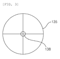
- FIG. 3 is a plan view of the wavelength plate according to an exemplary embodiment of the present invention.
- the central portion of the wavelength plate 135 is formed with the micro hole 138 so that the DC component region of the light beams whose images are focused on the central portion completely passes through the micro hole 138 and the region of the light beams having the spatial frequency components passes through the wavelength plate 135.
- the quantitative phase information for the specimen to be observed can be acquired and thus, the very delicate change in a cell unit that is hardly observed by the general optical microscope can be tracked.
- the present invention can be applied in the biological research field.
Landscapes
- Physics & Mathematics (AREA)
- Chemical & Material Sciences (AREA)
- Analytical Chemistry (AREA)
- General Physics & Mathematics (AREA)
- Optics & Photonics (AREA)
- Microscoopes, Condenser (AREA)
- Investigating Or Analysing Materials By Optical Means (AREA)
- Investigating, Analyzing Materials By Fluorescence Or Luminescence (AREA)
Applications Claiming Priority (1)
| Application Number | Priority Date | Filing Date | Title |
|---|---|---|---|
| KR1020080005810A KR100924574B1 (ko) | 2008-01-18 | 2008-01-18 | 편광 위상 현미경 |
Publications (2)
| Publication Number | Publication Date |
|---|---|
| EP2081070A2 true EP2081070A2 (fr) | 2009-07-22 |
| EP2081070A3 EP2081070A3 (fr) | 2009-07-29 |
Family
ID=40471076
Family Applications (1)
| Application Number | Title | Priority Date | Filing Date |
|---|---|---|---|
| EP09150365A Withdrawn EP2081070A3 (fr) | 2008-01-18 | 2009-01-12 | Microscope à phase polariscopique |
Country Status (4)
| Country | Link |
|---|---|
| US (1) | US7679038B2 (fr) |
| EP (1) | EP2081070A3 (fr) |
| JP (1) | JP5002604B2 (fr) |
| KR (1) | KR100924574B1 (fr) |
Cited By (2)
| Publication number | Priority date | Publication date | Assignee | Title |
|---|---|---|---|---|
| IT201600132813A1 (it) * | 2016-12-30 | 2018-06-30 | Istituto Naz Fisica Nucleare | Metodo e apparato per rilevare particelle di dimensioni subdiffrattive |
| TWI677705B (zh) * | 2018-04-09 | 2019-11-21 | 國立臺北科技大學 | 使用薩爾瓦稜鏡為剪切元件的剪切干涉顯微鏡 |
Families Citing this family (5)
| Publication number | Priority date | Publication date | Assignee | Title |
|---|---|---|---|---|
| JP5696396B2 (ja) * | 2010-08-16 | 2015-04-08 | ソニー株式会社 | 顕微鏡及びゴースト除去方法 |
| KR101593080B1 (ko) | 2014-01-22 | 2016-02-11 | 연세대학교 산학협력단 | 회절 위상 현미경 시스템 및 이를 이용한 측정방법 |
| JP6131204B2 (ja) | 2014-02-28 | 2017-05-17 | 富士フイルム株式会社 | 観察装置 |
| KR101938849B1 (ko) | 2017-12-28 | 2019-04-10 | 울산과학기술원 | 회절 위상 현미경 시스템의 동작 방법 및 이를 이용한 회절 위상 현미경 시스템 |
| CN111505817B (zh) * | 2020-04-30 | 2022-05-20 | 河北大学 | 基于偏振编码的相衬显微系统及其成像方法 |
Family Cites Families (13)
| Publication number | Priority date | Publication date | Assignee | Title |
|---|---|---|---|---|
| US3052152A (en) * | 1959-03-27 | 1962-09-04 | American Optical Corp | Optical compensating system |
| JPS57178211A (en) * | 1981-04-27 | 1982-11-02 | Nippon Kogaku Kk <Nikon> | Microscope optical system |
| US4765714A (en) * | 1984-04-03 | 1988-08-23 | Horner Joseph L | Binary phase-only optical correlation system |
| JP3253791B2 (ja) * | 1994-02-25 | 2002-02-04 | 三菱電機株式会社 | フーリエ変換光学系装置 |
| US5969855A (en) * | 1995-10-13 | 1999-10-19 | Olympus Optical Co., Ltd. | Microscope apparatus |
| JPH09281400A (ja) * | 1996-04-13 | 1997-10-31 | Nikon Corp | 物体観察装置 |
| KR100218665B1 (ko) * | 1997-01-13 | 1999-09-01 | 정선종 | 평판광학적위상-광세기변환용현미경 |
| JP2000269285A (ja) | 1999-03-15 | 2000-09-29 | Toshiba Corp | 半導体基板の欠陥検査装置 |
| JP2001194625A (ja) | 1999-10-27 | 2001-07-19 | Olympus Optical Co Ltd | 光画像処理装置 |
| US6924898B2 (en) | 2000-08-08 | 2005-08-02 | Zygo Corporation | Phase-shifting interferometry method and system |
| JP2004101403A (ja) * | 2002-09-11 | 2004-04-02 | Tokyo Seimitsu Co Ltd | 外観検査装置 |
| JP4645113B2 (ja) | 2004-09-21 | 2011-03-09 | 日本電気株式会社 | 光検査方法及び光検査装置並びに光検査システム |
| JP5055568B2 (ja) * | 2006-02-17 | 2012-10-24 | 株式会社ニコン | 位相差顕微鏡 |
-
2008
- 2008-01-18 KR KR1020080005810A patent/KR100924574B1/ko not_active IP Right Cessation
-
2009
- 2009-01-08 US US12/350,809 patent/US7679038B2/en not_active Expired - Fee Related
- 2009-01-12 EP EP09150365A patent/EP2081070A3/fr not_active Withdrawn
- 2009-01-14 JP JP2009005442A patent/JP5002604B2/ja not_active Expired - Fee Related
Non-Patent Citations (1)
| Title |
|---|
| None |
Cited By (3)
| Publication number | Priority date | Publication date | Assignee | Title |
|---|---|---|---|---|
| IT201600132813A1 (it) * | 2016-12-30 | 2018-06-30 | Istituto Naz Fisica Nucleare | Metodo e apparato per rilevare particelle di dimensioni subdiffrattive |
| WO2018122814A1 (fr) * | 2016-12-30 | 2018-07-05 | Istituto Nazionale Di Fisica Nucleare | Procédé et microscope optique permettant de détecter des particules ayant une taille sous-diffractive |
| TWI677705B (zh) * | 2018-04-09 | 2019-11-21 | 國立臺北科技大學 | 使用薩爾瓦稜鏡為剪切元件的剪切干涉顯微鏡 |
Also Published As
| Publication number | Publication date |
|---|---|
| US20090184240A1 (en) | 2009-07-23 |
| KR20090079670A (ko) | 2009-07-22 |
| US7679038B2 (en) | 2010-03-16 |
| EP2081070A3 (fr) | 2009-07-29 |
| JP2009169420A (ja) | 2009-07-30 |
| JP5002604B2 (ja) | 2012-08-15 |
| KR100924574B1 (ko) | 2009-10-30 |
Similar Documents
| Publication | Publication Date | Title |
|---|---|---|
| US7679038B2 (en) | Optical phase microscope using rotating 1/4 wavelength plate with pinhole in the center position and Fourier transformed lens | |
| EP2713195B1 (fr) | Microscopie à haute résolution au moyen de l'éclairage structuré sur de grandes distances de travail | |
| US8848199B2 (en) | Tomographic phase microscopy | |
| Chen et al. | Multi-color live-cell super-resolution volume imaging with multi-angle interference microscopy | |
| US9134110B2 (en) | Phase image acquisition device | |
| EP2910928B1 (fr) | Microscope drasc | |
| JP2018515744A (ja) | 光学測定装置および工程 | |
| CN106290284A (zh) | 结构光照明的双光子荧光显微系统与方法 | |
| JP4481397B2 (ja) | 光学装置及び顕微鏡 | |
| US20150185460A1 (en) | Image forming method and image forming apparatus | |
| EP2988092A1 (fr) | Appareil de mesure d'image optique | |
| EP2712542A1 (fr) | Ophtalmoscope d'éclairage structuré | |
| JP5109025B2 (ja) | 位相物体識別装置及び方法 | |
| CN116194818A (zh) | 观察装置和观察方法 | |
| US20180373010A1 (en) | Point-spread-function measurement device and measurement method, image acquisition apparatus, and image acquisition method | |
| EP2685239B1 (fr) | Microscope non linéaire et procédé d'observation non linéaire | |
| JP2009258080A (ja) | 穴形状測定装置 | |
| JP6623029B2 (ja) | 光学的距離計測装置 | |
| US10955349B2 (en) | Fluorescence observation device | |
| CN117007567A (zh) | 基于五芯光纤主动光操控的数字扫描光片荧光显微成像系统 | |
| Müllenbroich | Sensorless adaptive optics in advanced microscopy techniques | |
| POH | DEVELOPMENT OF HIGH-SPEED FOCAL MODULATION MICROSCOPY FOR VISUALIZATION OF THICK BIOLOGICAL SPECIMENS |
Legal Events
| Date | Code | Title | Description |
|---|---|---|---|
| PUAI | Public reference made under article 153(3) epc to a published international application that has entered the european phase |
Free format text: ORIGINAL CODE: 0009012 |
|
| PUAL | Search report despatched |
Free format text: ORIGINAL CODE: 0009013 |
|
| 17P | Request for examination filed |
Effective date: 20090112 |
|
| AK | Designated contracting states |
Kind code of ref document: A2 Designated state(s): AT BE BG CH CY CZ DE DK EE ES FI FR GB GR HR HU IE IS IT LI LT LU LV MC MK MT NL NO PL PT RO SE SI SK TR |
|
| AX | Request for extension of the european patent |
Extension state: AL BA RS |
|
| AK | Designated contracting states |
Kind code of ref document: A3 Designated state(s): AT BE BG CH CY CZ DE DK EE ES FI FR GB GR HR HU IE IS IT LI LT LU LV MC MK MT NL NO PL PT RO SE SI SK TR |
|
| AX | Request for extension of the european patent |
Extension state: AL BA RS |
|
| 17Q | First examination report despatched |
Effective date: 20100210 |
|
| AKX | Designation fees paid |
Designated state(s): DE FR GB |
|
| STAA | Information on the status of an ep patent application or granted ep patent |
Free format text: STATUS: THE APPLICATION IS DEEMED TO BE WITHDRAWN |
|
| 18D | Application deemed to be withdrawn |
Effective date: 20131019 |