EP2079184A2 - Contrôle de pouvoir pour transmission MDFO - Google Patents
Contrôle de pouvoir pour transmission MDFO Download PDFInfo
- Publication number
- EP2079184A2 EP2079184A2 EP09250018A EP09250018A EP2079184A2 EP 2079184 A2 EP2079184 A2 EP 2079184A2 EP 09250018 A EP09250018 A EP 09250018A EP 09250018 A EP09250018 A EP 09250018A EP 2079184 A2 EP2079184 A2 EP 2079184A2
- Authority
- EP
- European Patent Office
- Prior art keywords
- transmission
- signal
- frequency band
- power
- prescribed frequency
- Prior art date
- Legal status (The legal status is an assumption and is not a legal conclusion. Google has not performed a legal analysis and makes no representation as to the accuracy of the status listed.)
- Withdrawn
Links
Images


Classifications
-
- H—ELECTRICITY
- H04—ELECTRIC COMMUNICATION TECHNIQUE
- H04L—TRANSMISSION OF DIGITAL INFORMATION, e.g. TELEGRAPHIC COMMUNICATION
- H04L5/00—Arrangements affording multiple use of the transmission path
- H04L5/003—Arrangements for allocating sub-channels of the transmission path
-
- H—ELECTRICITY
- H04—ELECTRIC COMMUNICATION TECHNIQUE
- H04L—TRANSMISSION OF DIGITAL INFORMATION, e.g. TELEGRAPHIC COMMUNICATION
- H04L27/00—Modulated-carrier systems
- H04L27/0006—Assessment of spectral gaps suitable for allocating digitally modulated signals, e.g. for carrier allocation in cognitive radio
-
- H—ELECTRICITY
- H04—ELECTRIC COMMUNICATION TECHNIQUE
- H04W—WIRELESS COMMUNICATION NETWORKS
- H04W52/00—Power management, e.g. TPC [Transmission Power Control], power saving or power classes
- H04W52/04—TPC
- H04W52/38—TPC being performed in particular situations
- H04W52/42—TPC being performed in particular situations in systems with time, space, frequency or polarisation diversity
-
- H—ELECTRICITY
- H04—ELECTRIC COMMUNICATION TECHNIQUE
- H04L—TRANSMISSION OF DIGITAL INFORMATION, e.g. TELEGRAPHIC COMMUNICATION
- H04L27/00—Modulated-carrier systems
- H04L27/26—Systems using multi-frequency codes
- H04L27/2601—Multicarrier modulation systems
- H04L27/2602—Signal structure
- H04L27/2605—Symbol extensions, e.g. Zero Tail, Unique Word [UW]
- H04L27/2607—Cyclic extensions
-
- H—ELECTRICITY
- H04—ELECTRIC COMMUNICATION TECHNIQUE
- H04L—TRANSMISSION OF DIGITAL INFORMATION, e.g. TELEGRAPHIC COMMUNICATION
- H04L5/00—Arrangements affording multiple use of the transmission path
- H04L5/0001—Arrangements for dividing the transmission path
- H04L5/0003—Two-dimensional division
- H04L5/0005—Time-frequency
- H04L5/0007—Time-frequency the frequencies being orthogonal, e.g. OFDM(A), DMT
-
- H—ELECTRICITY
- H04—ELECTRIC COMMUNICATION TECHNIQUE
- H04L—TRANSMISSION OF DIGITAL INFORMATION, e.g. TELEGRAPHIC COMMUNICATION
- H04L5/00—Arrangements affording multiple use of the transmission path
- H04L5/003—Arrangements for allocating sub-channels of the transmission path
- H04L5/0058—Allocation criteria
- H04L5/0062—Avoidance of ingress interference, e.g. ham radio channels
Definitions
- the present invention contains subject matter related to Japanese Patent Application JP 2008-005070 filed in the Japan Patent Office on January 11, 2008, the entire contents of which being incorporated herein by reference.
- the present invention relates to a transmitting apparatus, a communication system, a transmitting method and a program.
- OFDM orthogonal frequency division multiplexing
- the Institute of Electrical and Electronic Engineers (IEEE) 802.11a which is one of wireless local area network (LAN) standards, wirelessly transmits data by the OFDM technology.
- ultra wideband (UWB) technology which is being promoted for the practical use, transmits a multicarrier signal using a high frequency such as the GHz band with a relatively wide bandwidth.
- interference with a carrier used in another communication network possibly occurs. This occurs, for example, in the case where a cellular phone in another communication network performs communication using a prescribed frequency that is included in the frequency band of a multicarrier signal. Because the occurrence of such interference causes degradation of a communication quality and even leads to a failure in communication, it is necessary to take appropriate measures to prevent the occurrence of interference at the OFDM transmitting end. As one of the measures, technology called detect and avoid (DAA) has been studied recently.
- the DAA is a technique that, when transmitting a multicarrier signal, stops transmission of a particular frequency band (e.g. a subcarrier unit) in a relatively wide frequency band for wireless transmission.
- FIGS. 10 and 11 are schematic views to explain the silent period.
- FIG. 10 is a schematic view showing a subcarrier before performing time domain transform by an inverse fast Fourier transformer (IFFT) of a transmitting apparatus in the frequency domain.
- IFFT inverse fast Fourier transformer
- a frequency band (SB) in which an interfered system possibly exists is specified in advance.
- the frequency band of an interfered system varies by country and region, and in the WiMAX standard in Europe, for example, it is mandatory to reduce a transmission power in a prescribed frequency band when the band is used by the WiMAX (interfered system).
- FIG. 11 is a schematic view showing the silent period in the time domain after performing time domain transform by the IFFT in the transmitting apparatus.
- the reduction of a transmission power is performed during the silent period SP (the portion indicated by dots in FIG. 11 ).
- Each regular interval including the silent period SP is referred to as SPC, and transmission is performed without reducing a transmission power as shown in FIG. 10 (a) during a non-silent period (NSP) in the SPC.
- NSP non-silent period
- transmission is performed by reducing a transmission power in the frequency band SB in which an interfered system possibly exists as shown in FIG. 10 (b) during the silent period SP in the SPC.
- the silent period time SP, the interval SPC, and the frequency band SB in which transmission is to be avoided may be regulated by the legal system of the country in which an interfered system exists.
- the silent period prevents noise in the OFDM transmission from affecting the detection of an interfered system when the interfered system exists. It is thereby possible to reliably detect the interfered system during the silent period. After detecting the interfered system, transmission is stopped only in the particular frequency band used by the interfered system by the DAA technology, thereby suppressing the effect on the interfered system.
- the silent period is set according to the above-described technique, a transmission power is reduced in a relatively wide frequency band in which an interfered system possibly exists, which causes degradation of reception characteristics during the silent period.
- the significant degradation of reception characteristics causes an increase in a retransmission signal or the like in spite of rate adaptation and so on, resulting in a decrease in overall throughput.
- a carrier to be transmitted is normally spread by a technique such as interleaving, frequency domain spreading and time domain spreading in order to suppress the degradation of reception characteristics.
- a transmission power is reduced in a relatively wide frequency band as shown in FIGS. 10 and 11 , a large part of the spread signal is contained in the frequency band in which a transmission power is reduced, making it difficult to decode the signal in a receiving apparatus.
- the reception characteristics of a particular signal with a reduced transmission power continue to be degraded even if an overall transmission rate is lowered. Therefore, the reception characteristics are degraded each time a transmission power is reduced in the silent period, causing an error in a reception packet.
- a transmitting apparatus including a transmission power reducing section to reduce a power of a transmission signal in a prescribed frequency band of a multicarrier signal containing a plurality of subcarriers, wherein the transmission power reducing section changes the prescribed frequency band in which the power of the transmission signal is reduced in time sequence.
- the power of the transmission signal is reduced in the prescribed frequency band of the multicarrier signal containing the plurality of subcarriers, and the prescribed frequency band in which the power of the transmission signal is reduced is changed in time sequence. Therefore, when detecting an interfered system by reducing a transmission power in the prescribed frequency band, it is possible to minimize the bandwidth of the prescribed frequency band and thereby minimize degradation of reception characteristics due to the reduction of the transmission power.
- the transmission power reducing section may reduce the power of the transmission signal in the prescribed frequency band equivalent to at least a part of a band corresponding to an interfered system and change the prescribed frequency band in time sequence within the band corresponding to the interfered system.
- the power of the transmission signal is reduced in at least a part of the band corresponding to the interfered system, and thus the transmission power is not reduced in the whole range of the band corresponding to the interfered system, it is possible to reliably suppress degradation of reception characteristics.
- the number of patterns of change in the prescribed frequency band may be set to a value obtained by dividing an interval of a silent period to be set for avoiding the interfered system by a time of the silent period.
- the prescribed frequency band in which the transmission power is reduced is spread over the number of patterns obtained by dividing the interval of the silent period by the time of the silent period, it is possible to suppress degradation of reception characteristics more reliably than the case of reducing the transmission power in the bandwidth of the silent period.
- the bandwidth of the prescribed frequency band may be set to a value obtained by dividing a bandwidth corresponding to the interfered system by the number of patterns.
- the prescribed frequency band in which the transmission power is reduced is set to the value obtained by dividing the bandwidth corresponding to the interfered system by the number of patterns, it is possible to suppress degradation of reception characteristics more reliably than the case of reducing the transmission power in the bandwidth of the silent period.
- the transmitting apparatus may further include an antenna to transmit the transmission signal.
- the transmitting apparatus including the antenna to transmit the transmission signal detects an interfered system by reducing a transmission power in the prescribed frequency band, it is possible to minimize the bandwidth of the prescribed frequency band and improve reception characteristics.
- a communication system including a transmitting apparatus and a receiving apparatus connected over a wireless communication network, wherein the transmitting apparatus includes a transmission power reducing section to reduce a power of a transmission signal in a prescribed frequency band of a multicarrier signal containing a plurality of subcarriers and change the prescribed frequency band in which the power of the transmission signal is reduced in time sequence, and the receiving apparatus includes a waveform shaping section to shape a waveform of a reception signal by cyclic addition to add a signal component extending off an effective symbol portion of a signal received from the transmitting apparatus to an opposite end of the effective symbol portion.
- the power of the transmission signal is reduced in the prescribed frequency band of the multicarrier signal containing the plurality of subcarriers, and the prescribed frequency band in which the power of the transmission signal is reduced is changed in time sequence in the transmitting apparatus. Therefore, when detecting an interfered system by reducing a transmission power in the prescribed frequency band, it is possible to minimize the bandwidth of the prescribed frequency band and thereby minimize degradation of reception characteristics due to the reduction of the transmission power.
- the waveform of the reception signal is shaped by cyclic addition that adds the signal component extending off the effective symbol portion of the signal received from the transmitting apparatus to the opposite end of the effective symbol portion. Therefore, even if the signal waveform is expanded in the time domain due to adjustment of the power of the transmission signal in the transmitting apparatus, it is possible to shape the waveform of the reception signal by the cyclic addition, thereby reliably suppressing degradation of reception characteristics.
- a transmitting method including the steps of reducing a power of a transmission signal in a prescribed frequency band of a multicarrier signal containing a plurality of subcarriers, and changing the prescribed frequency band in which the power of the transmission signal is reduced in time sequence.
- the power of the transmission signal is reduced in the prescribed frequency band of the multicarrier signal containing the plurality of subcarriers, and the prescribed frequency band in which the power of the transmission signal is reduced is changed in time sequence. Therefore, when detecting an interfered system by reducing a transmission power in the prescribed frequency band, it is possible to minimize the bandwidth of the prescribed frequency band and thereby minimize degradation of reception characteristics due to the reduction of the transmission power.
- the power of the transmission signal is reduced in the prescribed frequency band of the multicarrier signal containing the plurality of subcarriers, and the prescribed frequency band in which the power of the transmission signal is reduced is changed in time sequence. Therefore, when detecting an interfered system by reducing a transmission power in the prescribed frequency band, it is possible to minimize the bandwidth of the prescribed frequency band and thereby minimize degradation of reception characteristics due to the reduction of the transmission power.
- FIG. 1 is a schematic view showing the configuration of a transmitting apparatus 100 according to an embodiment of the present invention.
- the transmitting apparatus 100 is an example of an apparatus that performs transmission by OFDM.
- the transmitting apparatus 100 includes a MAC 102, an encoder 104, a modulator 106, a subcarrier-unit transmission avoidance circuit 108, an IFFT 110, a repetitive signal adding section 112, a guard interval inserting section 114, a waveform shaping section 116, a transmission power control section 118, a D-A converter (DAC) 120, a wireless transmitting section 122, and an antenna 124.
- DAC D-A converter
- Transmission data generated by the MAC 102 is encoded by the encoder 104 and modulated by the modulator 106 for wireless transmission.
- the transmission data (transmission symbol) modulated by the modulator 106 is transmitted to the subcarrier-unit transmission avoidance circuit 108.
- information about the location (position) of a subcarrier whose transmission is to be avoided is transmitted from the MAC 102 to the transmission avoidance circuit 108.
- the transmission avoidance circuit 108 Based on the information about the location of a subcarrier whose transmission is to be avoided that is transmitted from the MAC 102, the transmission avoidance circuit 108 replaces the data in the designated subcarrier location with a null signal.
- the processing in the transmission avoidance circuit 108 is described in detail later.
- the transmission symbol sequence that is partly replaced with the null signal by the transmission avoidance circuit 108 then undergoes orthogonal transformation from the frequency domain to the time domain by the IFFT 110, thereby being converted into a multicarrier signal.
- the processing of replacing data with a null signal performed in the transmission avoidance circuit 108 may replace data of only one subcarrier with a null signal or may replace data of a plurality of adjacent subcarriers with a null signal, for example.
- FIG. 2 is a schematic view showing processing to add a repetitive signal in the repetitive signal adding section 112.
- one transmission symbol length is Ts
- a symbols of a prescribed segment at the front end and the back end of an effective symbol Te in one symbol is added (copied) to the opposite end as a repetitive signal Tr.
- copies Tr of both the front end and the back end of the effective symbol Te are added in the example of FIG. 2
- a copy of either one end may be added.
- FIG. 2 also shows a guard interval Tg that is added by the guard interval inserting section 114.
- Ts Te+2Tr+Tg.
- the guard interval inserting section 114 adds the guard interval Tg by inserting a null signal, for example.
- the data of one transmission symbol in which the repetitive signal Tr is added by the repetitive signal adding section 112 and the guard interval Tg is inserted by the guard interval inserting section 114 is supplied to the waveform shaping section 116 where waveform shaping is performed.
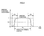
- the waveform shaping processing in the waveform shaping section 116 may be window multiplication that multiplies the transmission symbol with the repetitive signal Tr and the guard interval Tg by a coefficient of a window function, for example.
- FIG. 3 is a schematic view showing an example of a coefficient of a window function.
- the window function is a function that is set corresponding to the length of the effective symbol Te, of which level gradually increases and decreases at the front end and the back end of the effective symbol Te.
- the range 2Tr where the level of the window function increases and decreases is set to twice the repetitive signal Tr added by the copying described above.
- the transmission power control section 118 adjusts the overall transmission power in a time-domain waveform using the number of transmission-avoided subcarriers and a power level in the transmission avoidance position (information about a notch depth in the transmission avoidance position) as parameters. Because a transmission power is lowered when the notch is deep more than when the notch is shallow, the transmission power control section 118 increases the overall signal level as the notch is deepened so as to add the amount of power reduced by the notch as the overall signal power. Further, because a transmission power is lowered as the number of transmission-avoided subcarriers is larger, the transmission power control section 118 increases the overall signal level as the number of transmission-avoided subcarriers is larger.
- the signal with a transmission power controlled by the transmission power control section 118 is supplied to the D-A converter 120 and converted into an analog signal.
- the converted analog signal is supplied to the wireless transmitting section 122 and wirelessly transmitted at a prescribed transmission frequency from the antenna 124 connected thereto.
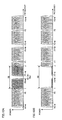
- FIG. 4 is a schematic view showing the state where the subcarrier in the transmission avoidance position is replaced with a null signal by the transmission avoidance circuit 108 in the frequency domain.
- the signals TX1, TX2, TX3 and TX4 respectively shown in FIGS. 4(a) to 4(d) are signals whose subcarrier in a prescribed frequency band is replaced with a null signal by the transmission avoidance circuit 108 after being output from the modulator 106.
- a transmission-limited band in which the subcarrier is replaced with a null signal in the frequency domain is set to four different bands.
- the transmission-limited band SB 1 is replaced with a null signal within the frequency range of plus-minus M from the center frequency F0.
- the band SB2 is replaced with a null signal within the frequency range of plus-minus M from the center frequency F0.
- the band SB3 is replaced with a null signal within the frequency range of plus-minus M from the center frequency F1.
- the band SB4 is replaced with a null signal within the frequency range of plus-minus M from the center frequency F1.
- the bands SB 1 to SB4 that are replaced with null signals correspond to the frequency band in which an interfered system possibly exists (the band SB in FIG. 10 ). In this manner, in this embodiment, only a part of the particular frequency band in which an interfered system possibly exists is replaced with a null signal, and the band to be replaced with a null signal is varied within the band SB.
- the information about the bands SB1 to SB4 whose transmission is to be avoided is periodically transmitted from the MAC 102 to the transmission avoidance circuit 108. Based on the periodically transmitted information, the transmission avoidance circuit 108 changes the band to be replaced with a null signal in time sequence in the order of SB1, SB2, SB3 and SB4.
- FIG. 5 shows the state where the signals TX1, TX2, TX3 and TX4 sequentially transmitted from the transmission avoidance circuit 108 are orthogonally transformed into the time domain by the IFFT 110 and spread in the time domain.
- the signal TX1 is spread in the time domain and transmitted twice during the interval of the transmission-limited time SP1.
- the signal TX2 is spread in the time domain during the interval of SP2
- the signal TX3 is spread in the time domain during the interval of SP3
- the signal TX4 is spread in the time domain during the interval of SP4.
- the frequency band of the null signal is varied in time sequence in each of the signals TX1 to TX4, the frequency bandwidth in which a transmission power is reduced at a time is minimized, thereby improving the overall throughput.
- the band in which a transmission power is reduced is indicated by dots.
- the configuration of a transmission power reducing section that changes the transmission-limited band SB1 to SB4 in time sequence is mainly implemented by the transmission avoidance circuit 108 and the IFFT 110.
- each of TX1 to TX4 the same signals are transmitted in the band of the center frequency F0-M and the band of the center frequency F0+M by frequency domain spreading. Furthermore, the signals transmitted in the band of F0-M and the band of F0+M are spread by interleaving. Likewise, the signals in the center frequency F1 ⁇ M and the signals in the center frequency F2 ⁇ M are also spread by frequency domain spreading and interleaving. Therefore, if the replacement with a null signal is performed in the narrow bands SB 1 to SB4, it is easy to perform decoding at the receiving end because the signals are spread. On the other hand, if the replacement with a null signal is performed in the relatively wide band SB as shown in FIG.
- one of the signals spread in the frequency domain is entirely replaced with a null signal, and it may be difficult to perform decoding at the receiving end. Therefore, by narrowing the bandwidth to be replaced with a null signal, it is possible to suppress the occurrence of a packet error and reliably improve the communication throughput in this embodiment.
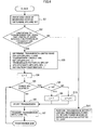
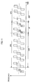
- FIG. 6 is a flowchart showing processing in the transmitting apparatus 100 according to the embodiment.
- step S1 the existence of an interfered system is checked.
- information such as a frequency band in which a transmission power is to be reduced is acquired from information such as a country and a region where the transmitting apparatus 100 is currently used.
- the acquired information includes the silent period time SP, the interval SPC and the band SB to set the silent period, which are described with reference to FIG. 10 .
- the configuration for receiving the signal in the transmitting apparatus 100 may be the same as the configuration of a receiving apparatus 200, which is described later.
- next step S2 it is determined whether it is necessary to limit transmission at a particular frequency for a given length of time at regular time intervals. In other words, it is determined whether it is necessary to set the silent period according the existence of an interfered system.
- step S3 If it is determined that an interfered system possibly exists and the silent period is necessary to be set based on the information acquired in the step S1, the process proceeds to the step S3. In other words, when it is determined that an interfered system possibly exists based on information such as a country and a region although it is not detected that communication is performed by the interfered system, the process proceeds to the step S3.
- the process proceeds to the step S11 and performs processing to constantly reduce a transmission power in the frequency band of the interfered system detected to exist without setting the silent period.
- step S2 determines whether no interfered system exists based on information such as a country and a region. If it is obvious in the step S2 that no interfered system exists based on information such as a country and a region, it is not necessary to reduce a transmission power in the frequency band corresponding to an interfered system. In such a case also, the process proceeds to the step S11 and performs transmission using the whole band without limiting a transmission power.
- the transmission-limited band SB1, SB2, SB3, SB4, etc. and the transmission-limited time SP1, SP2, SP3, SP4, etc. shown in FIGS. 4 and 5 , respectively, are determined based on the information about the time SP, the interval SPC and the band SB acquired in the step S1.
- the silent period time SP, the interval SPC and the band SB may be previously regulated by the legal system of a country, the specifications of an interfered system and so on as described earlier.
- the value of the transmission pattern N is not limited to a calculation result of the expression (1), and it may be set as appropriate. Although four kinds of transmission-limited bands are set in the example of FIG. 4 , it is feasible to set two kinds of transmission-limited bands and double the width of each transmission-limited band (e.g. to the width of SB1+SB2), for example.
- the silent period which has been set for the time SP in each interval SPC, can be spread over the transmission-limited time SP1, SP2, SP3, SP4, etc. within the interval SPC. Further, although the silent period has been set to the wide band SB, it can be spread over the narrower band SB1, SB2, SB3, SB4, etc. It is thereby possible to suppress the occurrence of a packet error and reliably improve the communication throughput.
- step S5 it is determined whether the period SPn has elapsed at the current time, and if the period SPn has not elapsed, transmission is started in the step S6, and a transmission waveform TXn is transmitted in the step S7. After the transmission waveform TXn is transmitted in the step S7, the process returns to the step S5 and repeats the subsequent processing.
- N 4 from the expression (1), so that the number of transmission signal patterns for transmission power reduction is four (TX1 to TX4) as shown in FIGS. 4 and 5 .
- the total 90MHz band is transmitted with a reduced transmission power during the interval of SPC, and if one subcarrier is 5MHz and the bandwidth of Null is 10MHz in the example of FIG. 4 , a transmission power is reduced for 4 carriers (20MHz) at a time. Accordingly, the signals are transmitted in the order of TX1, TX2, TX3, TX4, TX1, etc. within the given interval SPC as shown in FIG.
- the processing of FIG. 6 may be implemented by causing the transmitting apparatus 100 as a computer to function by a program (software) that is stored in memory included in the transmitting apparatus 100, for example.
- the bandwidth of one carrier is 10MHz in the WiMAX specification
- the transmission-limited band if the transmission-limited band is set to be narrower, it fails to receive a signal of an interfered system, thus failing to detect the existence of an interfered system. Accordingly, it is preferred to determine the bandwidth of the transmission-limited band (SB1, SB2, SB3, SB4, etc.) by taking the band of an interfered system into consideration.
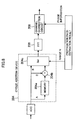
- FIG. 7 is a schematic view showing an example of the configuration of the receiving apparatus 200 to receive a signal transmitted from the transmitting apparatus 100.
- the transmitting apparatus 100 and the receiving apparatus 200 are connected over a wireless communication network by OFDM so as to communicate with each other.
- FIG. 7 mainly shows the configuration of a baseband processing section in a physical layer in an OFDM receiver, and the configuration of an upper layer such as an analog RF processing section that receives a radio signal and a MAC that processes decoded reception data is not shown.
- the analog RF processing section (not shown) amplifies a radio signal that is received via an antenna using a low noise amplifier (LNA) and performs frequency synthesis with a local signal to thereby down-concert the signal to an analog baseband signal. Further, it eliminates an unnecessary component different from a desired signal using a bandpass filter (BPF), amplifies the signal using a variable gain amplifier (VGA), and then performs analog to digital conversion.
- LNA low noise amplifier
- BPF bandpass filter
- VGA variable gain amplifier
- a synchronization detecting section 202 detects a synchronization timing from the reception signal in which multipath fading has occurred in a propagation path with use of a preamble portion of a packet.
- the transmitting apparatus 100 inserts the repetitive signal Tr into the guard interval period only when sending out a preamble signal, so that the receiving apparatus 200 can acquire synchronization with high accuracy.
- a waveform shaping section 204 performs waveform shaping by conducting cyclic addition to the head of the effective symbol using the guard interval portion or a delayed wave component that extends from the effective symbol of the reception signal to the guard interval portion.
- the signal waveform of the guard interval portion to which the delayed wave component at the head of the reception symbol is added becomes continuous, thereby eliminating interference between subcarriers.
- the fast Fourier transformer (FFT) 206 performs Fourier transform on the signal of a given symbol length. A time-domain signal is thereby transformed into a frequency-domain signal.
- FFT fast Fourier transformer
- a channel correction circuit 208 performs channel correction processing such as equalization, phase tracking and residual frequency offset compensation.
- the reception signal after the channel correction is demodulated by quadrature phase shift keying (QPSK), for example, by a demodulator 210, and further decoded using an error correcting code by a decoder 212 to become reception data.
- QPSK quadrature phase shift keying
- the reception data is then processed by the upper layer of a communication protocol.
- FIG. 8 is a schematic view showing an example of the configuration of the waveform shaping section 204 that is configured to determine the range of cyclic addition based on an estimation result of a propagation path.
- FIG. 9 is a schematic view to explain processing by the waveform shaping section 204.
- FIG. 9(a) shows a transmission signal
- FIG. 9(b) shows a reception signal
- FIG. 9(c) shows the way of cyclic addition.
- the operation of the waveform shaping section 204 is described hereinafter with reference to FIGS. 8 and 9 .
- the guard interval Tg is added after the effective symbol length of the transmission symbol.
- the effect of a delay appears in the reception symbol, so that the reception symbol is longer than the transmission symbol.
- the symbol extends off the head of the range to which FFT is applied as shown in FIG. 9(b) .
- the extending portion A in FIG. 9(b) corresponding to the range N of cyclic addition is retrieved and stored into memory 204a, and the portion B of the effective symbol length is output to a selector 204c in the subsequent stage.
- the portion C extending off the end of the effective symbol and corresponding to the range N of cyclic addition is retrieved, added with the portion A stored in the memory 204a (cf. FIG. 9(c) ) by an adder 204b, and output to the selector 204c.
- the selector 204c selectively outputs the portion B of the effective symbol length and the signal (A+C) added by the adder 204b to the FFT 206 in the subsequent stage.
- the signal waveform of the guard interval portion to which the delayed wave component at the head of the reception symbol is added becomes continuous. It is thereby possible to reduce the time-domain expansion of the reception signal even if the signal waveform is expanded in the time domain due to the effect of a multipath, waveform shaping by the window function and so on, thus reliably suppressing interference between subcarriers. This minimizes the noise component added to the reception symbol, thereby improving a reception SNR.
- the waveform shaping section 204 capable of conducting cyclic addition can be configured easily by the memory 204a, the adder 204b and the selector 204c.
- the embodiment when it is necessary to reduce a transmission power for a given length of time at regular intervals in order to detect the existence of an interfered system, it is possible to minimize the number of subcarriers (bandwidth) in which a transmission power is reduced. This prevents significant degradation of reception characteristics during the silent period. Further, because the bandwidth in which a transmission power is reduced is minimized, the receiving apparatus can reliably decode the signal that is spread by time domain spreading, frequency domain spreading, DCM modulation and so on.
Applications Claiming Priority (1)
| Application Number | Priority Date | Filing Date | Title |
|---|---|---|---|
| JP2008005070A JP4548487B2 (ja) | 2008-01-11 | 2008-01-11 | 送信装置、通信システム、送信方法及びプログラム |
Publications (2)
| Publication Number | Publication Date |
|---|---|
| EP2079184A2 true EP2079184A2 (fr) | 2009-07-15 |
| EP2079184A3 EP2079184A3 (fr) | 2010-03-24 |
Family
ID=40566207
Family Applications (1)
| Application Number | Title | Priority Date | Filing Date |
|---|---|---|---|
| EP09250018A Withdrawn EP2079184A3 (fr) | 2008-01-11 | 2009-01-06 | Contrôle de pouvoir pour transmission MDFO |
Country Status (4)
| Country | Link |
|---|---|
| US (1) | US8374259B2 (fr) |
| EP (1) | EP2079184A3 (fr) |
| JP (1) | JP4548487B2 (fr) |
| CN (1) | CN101483630B (fr) |
Cited By (1)
| Publication number | Priority date | Publication date | Assignee | Title |
|---|---|---|---|---|
| CN103369542A (zh) * | 2013-07-04 | 2013-10-23 | 河海大学 | 基于博弈论的同频异构网络功率分配方法 |
Families Citing this family (13)
| Publication number | Priority date | Publication date | Assignee | Title |
|---|---|---|---|---|
| US8634869B2 (en) * | 2006-09-15 | 2014-01-21 | Qualcomm Incorporated | Methods and apparatus related to multi-mode wireless communications device supporting both wide area network signaling and peer to peer signaling |
| US8369800B2 (en) * | 2006-09-15 | 2013-02-05 | Qualcomm Incorporated | Methods and apparatus related to power control and/or interference management in a mixed wireless communications system |
| US8929281B2 (en) * | 2006-09-15 | 2015-01-06 | Qualcomm Incorporated | Methods and apparatus related to peer to peer device |
| US8275319B2 (en) | 2009-03-11 | 2012-09-25 | Broadcom Corporation | Processing of multi-carrier signals before power amplifier amplification |
| KR101666009B1 (ko) * | 2009-10-22 | 2016-10-14 | 삼성전자주식회사 | 다중 셀 환경에서 피간섭 단말을 검출하고 간섭 제어를 수행하는 통신 시스템 |
| US8254510B2 (en) * | 2009-12-23 | 2012-08-28 | Industrial Technology Research Institute | Apparatus and method for inter-carrier interference cancellation |
| US8593983B2 (en) * | 2010-01-26 | 2013-11-26 | Entropic Communications, Inc. | Method and apparatus for use of silent symbols in a communications network |
| JP5648500B2 (ja) * | 2011-01-28 | 2015-01-07 | 富士通セミコンダクター株式会社 | 送信装置、送信方法、受信装置、及び受信方法 |
| US8908796B1 (en) * | 2013-05-15 | 2014-12-09 | University Of South Florida | Orthogonal frequency division multiplexing (OFDM) transmitter and receiver windowing for adjacent channel interference (ACI) suppression and rejection |
| US9763225B2 (en) * | 2013-10-07 | 2017-09-12 | Qualcomm Incorporated | LTE-U clear channel assessment operations |
| US9608696B2 (en) * | 2013-10-11 | 2017-03-28 | Qualcomm Incorporated | Dynamic transmit power and signal shaping |
| RU2754575C2 (ru) * | 2016-12-27 | 2021-09-03 | Шарп Кабусики Кайся | Терминальное устройство, устройство базовой станции и способ связи |
| EP3386158B1 (fr) * | 2017-04-07 | 2020-02-12 | Mitsubishi Electric R&D Centre Europe B.V. | Traitement de signal de domaine temporel numérique composite à base de sous-bande |
Citations (4)
| Publication number | Priority date | Publication date | Assignee | Title |
|---|---|---|---|---|
| JP2007166068A (ja) | 2005-12-12 | 2007-06-28 | Sony Corp | 無線通信装置及び無線通信方法 |
| JP2007243235A (ja) | 2006-03-03 | 2007-09-20 | Sony Corp | 無線通信装置及び無線通信方法、並びにコンピュータ・プログラム |
| JP2007243236A (ja) | 2006-03-03 | 2007-09-20 | Sony Corp | 無線通信システム、無線通信装置及び無線通信方法、並びにコンピュータ・プログラム |
| JP2007258904A (ja) | 2006-03-22 | 2007-10-04 | Sony Corp | 無線通信装置 |
Family Cites Families (17)
| Publication number | Priority date | Publication date | Assignee | Title |
|---|---|---|---|---|
| US6275522B1 (en) * | 1998-01-14 | 2001-08-14 | Motorola, Inc. | Method for allocating data and power in a discrete, multi-tone communication system |
| JP3607643B2 (ja) | 2001-07-13 | 2005-01-05 | 松下電器産業株式会社 | マルチキャリア送信装置、マルチキャリア受信装置、およびマルチキャリア無線通信方法 |
| JP4625361B2 (ja) * | 2005-04-25 | 2011-02-02 | 富士通株式会社 | 受信処理方法及び受信装置 |
| DE202005022046U1 (de) * | 2004-10-29 | 2012-08-24 | Sharp Kabushiki Kaisha | Funksender und Funkempfänger |
| US7453966B2 (en) * | 2005-01-12 | 2008-11-18 | Nokia Corporation | Gradient based method and apparatus for OFDM sub-carrier power optimization |
| JP4177830B2 (ja) * | 2005-03-31 | 2008-11-05 | 株式会社東芝 | 無線通信システムおよび無線通信端末 |
| JP4358169B2 (ja) * | 2005-08-25 | 2009-11-04 | 株式会社東芝 | 無線通信装置および無線通信方法 |
| JP4382729B2 (ja) * | 2005-09-22 | 2009-12-16 | 株式会社東芝 | 無線通信装置および無線通信方法 |
| JP4398927B2 (ja) * | 2005-09-22 | 2010-01-13 | 株式会社東芝 | 周波数利用状況測定システム |
| US20070147226A1 (en) * | 2005-10-27 | 2007-06-28 | Aamod Khandekar | Method and apparatus for achieving flexible bandwidth using variable guard bands |
| US7869529B2 (en) * | 2006-06-14 | 2011-01-11 | Qualcomm Incorporated | System, method and computer-readable medium for detection and avoidance (DAA) of victim services in ultra-wideband systems (UWB) |
| CN101461203B (zh) * | 2006-06-14 | 2013-03-27 | 艾格瑞系统有限公司 | 调制数据符号集的方法和设备及相应的解调方法和设备 |
| JP4952088B2 (ja) | 2006-06-23 | 2012-06-13 | ソニー株式会社 | 送信装置、送信方法、受信装置、受信方法及び伝送システム |
| JP4237784B2 (ja) * | 2006-08-04 | 2009-03-11 | 株式会社東芝 | 送信装置及び受信装置並びに無線通信システム |
| KR100766041B1 (ko) * | 2006-09-15 | 2007-10-12 | 삼성전자주식회사 | 초광대역 신호의 간섭 회피 방법 및 상기 방법을 수행하는초광대역 단말기 |
| DE602007007662D1 (de) * | 2006-12-12 | 2010-08-19 | Koninkl Philips Electronics Nv | Kommunikationsvorrichtung und kommunikationsverfahren mit sendepause für detektion und vermeidung |
| EP2128992A1 (fr) | 2008-05-30 | 2009-12-02 | STMicroelectronics N.V. | Procédé et dispositif pour cranter la bande de transmission d'un signal analogique, en particulier pour un mode d'opération détecter-et-éviter d'un système MB-OFDM |
-
2008
- 2008-01-11 JP JP2008005070A patent/JP4548487B2/ja not_active Expired - Fee Related
-
2009
- 2009-01-06 EP EP09250018A patent/EP2079184A3/fr not_active Withdrawn
- 2009-01-06 US US12/348,966 patent/US8374259B2/en active Active
- 2009-01-09 CN CN2009100030631A patent/CN101483630B/zh not_active Expired - Fee Related
Patent Citations (4)
| Publication number | Priority date | Publication date | Assignee | Title |
|---|---|---|---|---|
| JP2007166068A (ja) | 2005-12-12 | 2007-06-28 | Sony Corp | 無線通信装置及び無線通信方法 |
| JP2007243235A (ja) | 2006-03-03 | 2007-09-20 | Sony Corp | 無線通信装置及び無線通信方法、並びにコンピュータ・プログラム |
| JP2007243236A (ja) | 2006-03-03 | 2007-09-20 | Sony Corp | 無線通信システム、無線通信装置及び無線通信方法、並びにコンピュータ・プログラム |
| JP2007258904A (ja) | 2006-03-22 | 2007-10-04 | Sony Corp | 無線通信装置 |
Cited By (2)
| Publication number | Priority date | Publication date | Assignee | Title |
|---|---|---|---|---|
| CN103369542A (zh) * | 2013-07-04 | 2013-10-23 | 河海大学 | 基于博弈论的同频异构网络功率分配方法 |
| CN103369542B (zh) * | 2013-07-04 | 2016-08-31 | 河海大学 | 基于博弈论的同频异构网络功率分配方法 |
Also Published As
| Publication number | Publication date |
|---|---|
| CN101483630A (zh) | 2009-07-15 |
| JP2009171073A (ja) | 2009-07-30 |
| CN101483630B (zh) | 2013-02-06 |
| US8374259B2 (en) | 2013-02-12 |
| JP4548487B2 (ja) | 2010-09-22 |
| US20090180560A1 (en) | 2009-07-16 |
| EP2079184A3 (fr) | 2010-03-24 |
Similar Documents
| Publication | Publication Date | Title |
|---|---|---|
| US8374259B2 (en) | Transmitting apparatus, communication system, transmitting method and program | |
| US9912505B2 (en) | Pilot design for wireless system | |
| US7602696B2 (en) | Adaptive guard intervals in OFDM systems | |
| KR101820731B1 (ko) | 다수의 직교 주파수 분할 다중 파라미터 셋을 지원하는 무선통신 시스템에서 통신 방법 및 장치 | |
| CN1951033B (zh) | 宽带无线通信系统中使多载波和直接序列扩频信号重叠的方法和设备 | |
| EP1488590B1 (fr) | Recepteur sans fil a canaux multiples | |
| US8644399B2 (en) | Transmission apparatus, transmission method, reception apparatus, reception method, and transmission system | |
| US20080219235A1 (en) | System and Method for Frequency Division Multiple Access Communications | |
| KR101459014B1 (ko) | 이동통신 시스템의 주파수 제어 장치 및 방법 | |
| JP2009505566A (ja) | パイロット信号を送信するための方法および装置 | |
| KR20060116019A (ko) | 광대역 무선 통신 시스템에서 다중-반송파 및 직접 시퀀스확산 스펙트럼 신호를 중첩시키는 방법 및 장치 | |
| KR20110074620A (ko) | 통신 장치, 통신 방법 및 집적 회로 | |
| US20070230635A1 (en) | Wireless communication reception with cooperation between agc and digital baseband | |
| US7539123B2 (en) | Subcarrier puncturing in communication systems | |
| US20140078920A1 (en) | Systems and methods for wireless communication | |
| JP2011014982A (ja) | 無線受信装置 | |
| JP5008994B2 (ja) | 通信システム、基地局、端末及び通信方法 | |
| US20100184380A1 (en) | Mitigating intercarrier and intersymbol interference in asynchronous wireless communications | |
| JP4874178B2 (ja) | 無線送信方法、伝搬路推定方法、無線送信機、無線受信機および無線通信システム | |
| JP2009171071A (ja) | 送信装置、通信システム及び送信方法 | |
| JP2008258992A (ja) | 無線通信装置 | |
| JP2007243235A (ja) | 無線通信装置及び無線通信方法、並びにコンピュータ・プログラム | |
| JP4351240B2 (ja) | Tdd/ofdma通信方式の通信制御方法、基地局装置、端末装置および通信制御システム | |
| JPWO2006095874A1 (ja) | 無線送信装置及び無線受信装置 |
Legal Events
| Date | Code | Title | Description |
|---|---|---|---|
| PUAI | Public reference made under article 153(3) epc to a published international application that has entered the european phase |
Free format text: ORIGINAL CODE: 0009012 |
|
| 17P | Request for examination filed |
Effective date: 20090106 |
|
| AK | Designated contracting states |
Kind code of ref document: A2 Designated state(s): AT BE BG CH CY CZ DE DK EE ES FI FR GB GR HR HU IE IS IT LI LT LU LV MC MK MT NL NO PL PT RO SE SI SK TR |
|
| AX | Request for extension of the european patent |
Extension state: AL BA RS |
|
| PUAL | Search report despatched |
Free format text: ORIGINAL CODE: 0009013 |
|
| AK | Designated contracting states |
Kind code of ref document: A3 Designated state(s): AT BE BG CH CY CZ DE DK EE ES FI FR GB GR HR HU IE IS IT LI LT LU LV MC MK MT NL NO PL PT RO SE SI SK TR |
|
| AX | Request for extension of the european patent |
Extension state: AL BA RS |
|
| RIC1 | Information provided on ipc code assigned before grant |
Ipc: H04L 5/00 20060101ALN20100212BHEP Ipc: H04L 27/00 20060101AFI20100212BHEP |
|
| 17Q | First examination report despatched |
Effective date: 20100610 |
|
| AKX | Designation fees paid |
Designated state(s): DE FR GB |
|
| STAA | Information on the status of an ep patent application or granted ep patent |
Free format text: STATUS: THE APPLICATION IS DEEMED TO BE WITHDRAWN |
|
| 18D | Application deemed to be withdrawn |
Effective date: 20150708 |