EP2078813A2 - Betätigungssystem und Falttafelvorrichtung - Google Patents
Betätigungssystem und Falttafelvorrichtung Download PDFInfo
- Publication number
- EP2078813A2 EP2078813A2 EP09250073A EP09250073A EP2078813A2 EP 2078813 A2 EP2078813 A2 EP 2078813A2 EP 09250073 A EP09250073 A EP 09250073A EP 09250073 A EP09250073 A EP 09250073A EP 2078813 A2 EP2078813 A2 EP 2078813A2
- Authority
- EP
- European Patent Office
- Prior art keywords
- panel
- track
- actuating system
- carriage
- panels
- Prior art date
- Legal status (The legal status is an assumption and is not a legal conclusion. Google has not performed a legal analysis and makes no representation as to the accuracy of the status listed.)
- Withdrawn
Links
- 230000000712 assembly Effects 0.000 description 4
- 238000000429 assembly Methods 0.000 description 4
- 238000011109 contamination Methods 0.000 description 3
- 230000004048 modification Effects 0.000 description 3
- 238000012986 modification Methods 0.000 description 3
- 230000015572 biosynthetic process Effects 0.000 description 2
- 230000014509 gene expression Effects 0.000 description 2
- 230000007257 malfunction Effects 0.000 description 2
- 230000009471 action Effects 0.000 description 1
- 230000001154 acute effect Effects 0.000 description 1
- 238000007792 addition Methods 0.000 description 1
- 230000008901 benefit Effects 0.000 description 1
- 230000005540 biological transmission Effects 0.000 description 1
- 238000010276 construction Methods 0.000 description 1
- 230000006872 improvement Effects 0.000 description 1
- 230000000977 initiatory effect Effects 0.000 description 1
- 230000004044 response Effects 0.000 description 1
- 230000000717 retained effect Effects 0.000 description 1
- 239000000725 suspension Substances 0.000 description 1
Images


Classifications
-
- E—FIXED CONSTRUCTIONS
- E05—LOCKS; KEYS; WINDOW OR DOOR FITTINGS; SAFES
- E05D—HINGES OR SUSPENSION DEVICES FOR DOORS, WINDOWS OR WINGS
- E05D15/00—Suspension arrangements for wings
- E05D15/26—Suspension arrangements for wings for folding wings
-
- E—FIXED CONSTRUCTIONS
- E05—LOCKS; KEYS; WINDOW OR DOOR FITTINGS; SAFES
- E05F—DEVICES FOR MOVING WINGS INTO OPEN OR CLOSED POSITION; CHECKS FOR WINGS; WING FITTINGS NOT OTHERWISE PROVIDED FOR, CONCERNED WITH THE FUNCTIONING OF THE WING
- E05F15/00—Power-operated mechanisms for wings
- E05F15/60—Power-operated mechanisms for wings using electrical actuators
- E05F15/603—Power-operated mechanisms for wings using electrical actuators using rotary electromotors
- E05F15/605—Power-operated mechanisms for wings using electrical actuators using rotary electromotors for folding wings
-
- E—FIXED CONSTRUCTIONS
- E05—LOCKS; KEYS; WINDOW OR DOOR FITTINGS; SAFES
- E05Y—INDEXING SCHEME ASSOCIATED WITH SUBCLASSES E05D AND E05F, RELATING TO CONSTRUCTION ELEMENTS, ELECTRIC CONTROL, POWER SUPPLY, POWER SIGNAL OR TRANSMISSION, USER INTERFACES, MOUNTING OR COUPLING, DETAILS, ACCESSORIES, AUXILIARY OPERATIONS NOT OTHERWISE PROVIDED FOR, APPLICATION THEREOF
- E05Y2201/00—Constructional elements; Accessories therefor
- E05Y2201/60—Suspension or transmission members; Accessories therefor
- E05Y2201/622—Suspension or transmission members elements
- E05Y2201/624—Arms
- E05Y2201/626—Levers
-
- E—FIXED CONSTRUCTIONS
- E05—LOCKS; KEYS; WINDOW OR DOOR FITTINGS; SAFES
- E05Y—INDEXING SCHEME ASSOCIATED WITH SUBCLASSES E05D AND E05F, RELATING TO CONSTRUCTION ELEMENTS, ELECTRIC CONTROL, POWER SUPPLY, POWER SIGNAL OR TRANSMISSION, USER INTERFACES, MOUNTING OR COUPLING, DETAILS, ACCESSORIES, AUXILIARY OPERATIONS NOT OTHERWISE PROVIDED FOR, APPLICATION THEREOF
- E05Y2201/00—Constructional elements; Accessories therefor
- E05Y2201/60—Suspension or transmission members; Accessories therefor
- E05Y2201/622—Suspension or transmission members elements
- E05Y2201/644—Flexible elongated pulling elements
- E05Y2201/654—Cables
-
- E—FIXED CONSTRUCTIONS
- E05—LOCKS; KEYS; WINDOW OR DOOR FITTINGS; SAFES
- E05Y—INDEXING SCHEME ASSOCIATED WITH SUBCLASSES E05D AND E05F, RELATING TO CONSTRUCTION ELEMENTS, ELECTRIC CONTROL, POWER SUPPLY, POWER SIGNAL OR TRANSMISSION, USER INTERFACES, MOUNTING OR COUPLING, DETAILS, ACCESSORIES, AUXILIARY OPERATIONS NOT OTHERWISE PROVIDED FOR, APPLICATION THEREOF
- E05Y2201/00—Constructional elements; Accessories therefor
- E05Y2201/60—Suspension or transmission members; Accessories therefor
- E05Y2201/622—Suspension or transmission members elements
- E05Y2201/686—Rods, links
-
- E—FIXED CONSTRUCTIONS
- E05—LOCKS; KEYS; WINDOW OR DOOR FITTINGS; SAFES
- E05Y—INDEXING SCHEME ASSOCIATED WITH SUBCLASSES E05D AND E05F, RELATING TO CONSTRUCTION ELEMENTS, ELECTRIC CONTROL, POWER SUPPLY, POWER SIGNAL OR TRANSMISSION, USER INTERFACES, MOUNTING OR COUPLING, DETAILS, ACCESSORIES, AUXILIARY OPERATIONS NOT OTHERWISE PROVIDED FOR, APPLICATION THEREOF
- E05Y2900/00—Application of doors, windows, wings or fittings thereof
- E05Y2900/10—Application of doors, windows, wings or fittings thereof for buildings or parts thereof
- E05Y2900/13—Type of wing
- E05Y2900/132—Doors
Definitions
- the invention relates to an actuating system for a folding panel assembly and to a folding panel assembly incorporating same.
- Folding panel assemblies such as folding doors, using an actuating system for operating and guiding its movement are known.
- One typical folding panel assembly is described in US 6470952 and includes at least first and second, substantially rectangular panels, the first panel having first and second vertical ends, and the second panel having third and fourth vertical ends, the second and third vertical ends being hinged to one another about a hinge axis parallel thereto.
- An actuating system includes a substantially horizontal track, with a first pivot support for connection to the first panel, a carriage traversable along the track, with a second pivot support for connection to the second panel.
- the actuating system further includes a flexible drive element arranged parallel to the track and in engagement with the carriage for traversing same along the track.
- an object of the present invention to propose an improved actuating system for a folding panel assembly that is less susceptible to contamination, but which can still be unobtrusively incorporated in the actuating system.
- the invention provides an actuating system for a folding panel assembly, with the folding panel assembly including at least first and second, substantially rectangular panels, the first panel having first and second vertical ends, and the second panel having third and fourth vertical ends, the second and third vertical ends being hinged to one another about a hinge axis parallel thereto, the actuating system including a substantially horizontal track, having a first pivot support for connection to the first panel; a carriage traversable along the track, having a second pivot support for connection to the second panel; and a flexible drive element arranged parallel to the track and in engagement with the carriage for traversing same along the track, wherein an elongated connecting rod has a first longitudinal end pivotally connected to the carriage and a second, opposite longitudinal end pivotally connectable to the first panel at a location adjacent to the second vertical end thereof and wherein a line through the first and second longitudinal ends of the elongated connecting rod, in use, is excluded from becoming aligned with respect to the first panel in any position of the carriage along the track.
- the flexible drive element can be looped around at least a first pulley wheel, located in a vicinity of a longitudinal end of the track. This enables to subject opposite ends of the flexible drive element to a pulling action, to move same in opposite directions, from one and the same longitudinal end of the track. It is further advantageous for the, or a further pulley wheel to be rotationally drivable for traversing the carriage. In such a case the pulley wheel may be drivable connected to an electric motor.
- the invention also provides a folding panel assembly including the subject actuating system and at least first and second, substantially rectangular panels, the first panel having first and second vertical ends, and the second panel having third and fourth vertical ends, the second and third vertical ends being hinged to one another about a hinge axis parallel thereto, the first panel being connected to the first pivot support, the second pivot support being connected to the second panel and wherein the first panel is pivotally connected to the second longitudinal end of the elongated connecting rod.
- a folding panel assembly including the subject actuating system and at least first and second, substantially rectangular panels, the first panel having first and second vertical ends, and the second panel having third and fourth vertical ends, the second and third vertical ends being hinged to one another about a hinge axis parallel thereto, the first panel being connected to the first pivot support, the second pivot support being connected to the second panel and wherein the first panel is pivotally connected to the second longitudinal end of the elongated connecting rod.
- folding panel assembly may be further improved if the first and second panels are made to equal width and/or if the first and second panels are suspended from the track being arranged in an overhead position.
- the folding panel assembly may then further include a bottom rail for guiding the first and second panels at a lower end thereof.
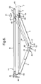
- the folding panel assembly 1 has a first substantially rectangular panel 3 and a second similarly rectangular panel 5.
- the first and second panels 3, 5 are suspended from an overhead track 7 in a manner to be described herein below.
- the first and second panels 3, 5 can be guided by an optional bottom rail 9.
- the track 7 forms part of an actuating system, generally referenced as "11", which actuating system will be described in reference to Figures 5 to 8 .
- the first panel 3 has a first vertical end 13 and a second vertical end 15.
- the second panel 5 has a third vertical end 17 and a fourth vertical end 19.
- the first and second vertical ends 13, 15 of the first panel 3 are joined by an upper horizontal end 21 and a lower horizontal end 23.
- the third and fourth vertical ends 17, 19 of the second panel 5 are joined by an upper horizontal end 25 and a lower horizontal end 27.
- the actuating system 11 as shown in Figures 5 to 8 has a looped driving belt 31 with a return pulley 33 at one longitudinal end, defining two parallel branches of the flexible drive belt 31, and an electric driving motor 35 at an opposite longitudinal end.
- the flexible drive element 31 extends parallel to the track 7 and a carriage 37 traversably carried and guided by the track through a shoe 39 is attached to one of the branches of the looped driving belt 31 extends along the track 7 at a slight distance determined by a first extension 41 of track 7, supporting the return pulley 33 and a second extension 43 carrying the drive motor 35.
- the carriage 37 has an extension arm 45 which carries an engagement member 47 which engages the flexible drive element 31.
- the engagement member 47 is provided with a first pivot 49 which pivotally receives a first longitudinal end of a connection rod 51.
- the connecting rod 51 extends to a second pivot 53 by which it is pivotally connected to the first panel 3 in a location adjacent to the second vertical end 15.
- the second vertical end 15 of the first panel 3 is hingedly connected to the third vertical end of the second panel 5 by a hinge formation 55.
- the hinge formation 55 can be formed by a so called piano hinge but also by any other suitable form of hinge.
- a particularly suitable alternative form of hinge may be formed by virtual hinge arrangements such as those proposed by FR 1 293 576 or DE 2455 658 .
- the hinge axis is best positioned adjacent to the side of the panels facing the actuating system 11 as this will enable a close joint between the vertical ends 15, 17 of the first and second panel 3, 5 on a side thereof substantially hiding the actuating system 11.
- a longitudinal centre line of the connecting rod 51 which includes the first and second pivots 49, 51 extends at an acute angle with respect to the track 7 and the common plane in which the first and second panel 3, 5 are in a closed position.
- the connecting rod 51 is provided and is arranged so that it remains at an included angle with the track 7, which in any position of the carriage 37 along the track 7 excludes the connecting rod 51 from becoming aligned with respect to the first panel 3.
- Figures 7 and 8 show further opening stages of the folding panel assembly 1, wherein Figure 8 represents the fully opened position. Comparing the relative position of the first panel 3 and the connecting rod 51 in Figures 5 and 8 , it will be apparent that the connecting rod 51 will not in any position of its movement become aligned with the first panel 3.
- the electric driving motor 35 is not shown in much detail, but the skilled person will appreciate that this can also include some kind of gear transmission and a further pulley wheel similar to pulley wheel 33 for drivingly engaging the flexible drive element or belt 31.
- the first and second panels 3 and 5 are particularly suitable for execution in a form of framed louvers for the attachment to the outside of building structures.
- the louvre frame can then be defined by the vertical and upper and lower ends op the panels.
- Louvre panels may be retained there between in either a horizontal or a vertical orientation and each of the individual louvers may be pivotally adjustable for angular orientation.
- the folding panel assembly can also be executed as a bi-folding structure with third and fourth panels arranged symmetrically with respect to the first and second panels.
Landscapes
- Engineering & Computer Science (AREA)
- Mechanical Engineering (AREA)
- Extensible Doors And Revolving Doors (AREA)
- Folding Of Thin Sheet-Like Materials, Special Discharging Devices, And Others (AREA)
- Power-Operated Mechanisms For Wings (AREA)
Priority Applications (1)
| Application Number | Priority Date | Filing Date | Title |
|---|---|---|---|
| EP09250073.5A EP2078813A3 (de) | 2008-01-14 | 2009-01-12 | Betätigungssystem und Falttafelvorrichtung |
Applications Claiming Priority (2)
| Application Number | Priority Date | Filing Date | Title |
|---|---|---|---|
| EP08000556 | 2008-01-14 | ||
| EP09250073.5A EP2078813A3 (de) | 2008-01-14 | 2009-01-12 | Betätigungssystem und Falttafelvorrichtung |
Publications (2)
| Publication Number | Publication Date |
|---|---|
| EP2078813A2 true EP2078813A2 (de) | 2009-07-15 |
| EP2078813A3 EP2078813A3 (de) | 2014-03-12 |
Family
ID=40436328
Family Applications (1)
| Application Number | Title | Priority Date | Filing Date |
|---|---|---|---|
| EP09250073.5A Withdrawn EP2078813A3 (de) | 2008-01-14 | 2009-01-12 | Betätigungssystem und Falttafelvorrichtung |
Country Status (5)
| Country | Link |
|---|---|
| US (1) | US8096341B2 (de) |
| EP (1) | EP2078813A3 (de) |
| AU (1) | AU2009200126B2 (de) |
| BR (1) | BRPI0900486B1 (de) |
| MX (1) | MX2009000474A (de) |
Cited By (3)
| Publication number | Priority date | Publication date | Assignee | Title |
|---|---|---|---|---|
| BE1019437A3 (nl) * | 2010-07-27 | 2012-07-03 | D & G Construct | Gemotoriseerd opvouwbaar paneelsysteem. |
| WO2013023737A3 (de) * | 2011-08-17 | 2013-05-02 | Weinor Gmbh & Co. Kg | Schiebefalttürsystem |
| IT202200002462A1 (it) * | 2022-02-10 | 2023-08-10 | Salice Arturo Spa | Dispositivo di comando per porte ripiegabili di armadi, cabine armadio o mobili in genere |
Families Citing this family (16)
| Publication number | Priority date | Publication date | Assignee | Title |
|---|---|---|---|---|
| DE102011120839B4 (de) * | 2011-12-13 | 2016-02-25 | Diehl Comfort Modules GmbH | Automatisch betriebene Türanlage für eine Flugzeugtoilette |
| US9085926B2 (en) * | 2013-03-15 | 2015-07-21 | Wallace International Ltd. | Trackless folding panel gate |
| US20150075073A1 (en) * | 2013-09-19 | 2015-03-19 | Ensign-Bickford Industries, Inc. | Security barrier system |
| US20150218865A1 (en) * | 2014-02-04 | 2015-08-06 | Custom Service Hardware, Inc. | Cantilevered bi-fold door support |
| US9428259B2 (en) | 2014-03-27 | 2016-08-30 | C&D Zodiac, Inc. | Bi-fold door module |
| RU2679185C2 (ru) * | 2014-03-27 | 2019-02-06 | Си Энд Ди ЗОДИАК, ИНК. | Блок складной двери |
| US9115531B1 (en) * | 2014-04-28 | 2015-08-25 | Nien Made Enterprise Co., Ltd. | Covering of building's opening |
| AT517343B1 (de) * | 2015-06-29 | 2017-01-15 | Blum Gmbh Julius | Ausstoßvorrichtung für eine Falttür oder Falt-Schiebe-Tür |
| US9695623B2 (en) * | 2015-09-09 | 2017-07-04 | Derek Keith Thomas | Powered folding doors |
| EP3601049B1 (de) * | 2017-03-21 | 2024-07-03 | Safran Cabin Netherlands N.V. | Türen für bordküchenwagenfächer |
| US10669772B2 (en) * | 2017-05-05 | 2020-06-02 | Modernfold, Inc. | Anti-float systems and methods |
| AT519674B1 (de) * | 2017-05-11 | 2018-09-15 | Blum Gmbh Julius | Ausstoßvorrichtung für eine Falttür |
| IT201800004535A1 (it) * | 2018-04-16 | 2019-10-16 | Ante incernierate per armadi, cabine armadio e mobili in genere con dispositivi di smorzamento e richiamo magnetici | |
| WO2020082112A1 (en) * | 2018-10-24 | 2020-04-30 | Centor Design Pty Ltd | A foldback door and system |
| US11098511B2 (en) | 2018-12-20 | 2021-08-24 | Pgt Innovations, Inc. | Sliding door system with dual track assemblies |
| US11098514B2 (en) | 2018-12-20 | 2021-08-24 | Pgt Innovations, Inc. | Sliding door system with mono-track assemblies |
Citations (3)
| Publication number | Priority date | Publication date | Assignee | Title |
|---|---|---|---|---|
| FR1293576A (fr) | 1961-03-27 | 1962-05-18 | Ile D Etudes Et De Rech S Tech | Fermeture de baie à repli accordéon |
| DE2455658A1 (de) | 1974-11-25 | 1976-08-12 | Greschbach Stahlbau | Schiebefalttor |
| US6470952B1 (en) | 2001-06-06 | 2002-10-29 | John Cline | Bi-folding door |
Family Cites Families (14)
| Publication number | Priority date | Publication date | Assignee | Title |
|---|---|---|---|---|
| US2614627A (en) * | 1949-11-14 | 1952-10-21 | Robert E Miller | Folding door |
| US3181596A (en) * | 1962-11-29 | 1965-05-04 | American Sereen Products Compa | Bi-fold door unit |
| US3314534A (en) * | 1963-04-30 | 1967-04-18 | American Screen Products Compa | Pre-assembled, pre-hung door unit |
| US3275064A (en) * | 1964-08-14 | 1966-09-27 | Hansen Leslie Niels | Folding door |
| US3342246A (en) * | 1965-02-08 | 1967-09-19 | Stanley Works | Guide assembly for bifolding doors |
| US3605853A (en) * | 1969-04-01 | 1971-09-20 | Norman W Osborn | Folding-door constructions and installations |
| US4276919A (en) * | 1977-06-16 | 1981-07-07 | Walters Kenneth I | Enclosure doors |
| US4269254A (en) * | 1979-03-05 | 1981-05-26 | Horton Francis B | Trolley and track |
| US4427049A (en) * | 1980-12-03 | 1984-01-24 | Belanger, Inc. | Power operated bi-fold strip curtain door assembly |
| US4852628A (en) * | 1987-04-27 | 1989-08-01 | Labex Gmbh | Suspension system for folding door |
| US4957600A (en) * | 1989-06-26 | 1990-09-18 | Kelly Company Inc. | Bi-fold door construction |
| US5143137A (en) * | 1990-03-08 | 1992-09-01 | Rite-Hite Corporation | Overlapping seal for insulated folding door |
| EP0561091A1 (de) * | 1992-03-16 | 1993-09-22 | Jean Paul Coron | Vorrichtung zum Öffnen und Schliessen von Garagentoren, Toren und ähnlichen Verschlüssen |
| US6098695A (en) * | 1998-11-20 | 2000-08-08 | Rite-Hite Holding Corporation | Stabilizer arm for a folding door |
-
2009
- 2009-01-12 EP EP09250073.5A patent/EP2078813A3/de not_active Withdrawn
- 2009-01-13 MX MX2009000474A patent/MX2009000474A/es active IP Right Grant
- 2009-01-13 AU AU2009200126A patent/AU2009200126B2/en active Active
- 2009-01-13 US US12/352,662 patent/US8096341B2/en not_active Expired - Fee Related
- 2009-01-14 BR BRPI0900486A patent/BRPI0900486B1/pt active IP Right Grant
Patent Citations (3)
| Publication number | Priority date | Publication date | Assignee | Title |
|---|---|---|---|---|
| FR1293576A (fr) | 1961-03-27 | 1962-05-18 | Ile D Etudes Et De Rech S Tech | Fermeture de baie à repli accordéon |
| DE2455658A1 (de) | 1974-11-25 | 1976-08-12 | Greschbach Stahlbau | Schiebefalttor |
| US6470952B1 (en) | 2001-06-06 | 2002-10-29 | John Cline | Bi-folding door |
Cited By (5)
| Publication number | Priority date | Publication date | Assignee | Title |
|---|---|---|---|---|
| BE1019437A3 (nl) * | 2010-07-27 | 2012-07-03 | D & G Construct | Gemotoriseerd opvouwbaar paneelsysteem. |
| WO2013023737A3 (de) * | 2011-08-17 | 2013-05-02 | Weinor Gmbh & Co. Kg | Schiebefalttürsystem |
| CN103703204A (zh) * | 2011-08-17 | 2014-04-02 | 威诺有限两合公司 | 滑动折叠门系统 |
| IT202200002462A1 (it) * | 2022-02-10 | 2023-08-10 | Salice Arturo Spa | Dispositivo di comando per porte ripiegabili di armadi, cabine armadio o mobili in genere |
| WO2023151964A1 (en) * | 2022-02-10 | 2023-08-17 | Arturo Salice S.P.A. | Drive device for foldable doors of wardrobes, walk-in closets or pieces of furniture in general |
Also Published As
| Publication number | Publication date |
|---|---|
| AU2009200126A1 (en) | 2009-07-30 |
| US20090178770A1 (en) | 2009-07-16 |
| EP2078813A3 (de) | 2014-03-12 |
| US8096341B2 (en) | 2012-01-17 |
| MX2009000474A (es) | 2009-08-28 |
| BRPI0900486B1 (pt) | 2018-11-21 |
| AU2009200126B2 (en) | 2015-11-26 |
| BRPI0900486A2 (pt) | 2010-01-19 |
Similar Documents
| Publication | Publication Date | Title |
|---|---|---|
| EP2078813A2 (de) | Betätigungssystem und Falttafelvorrichtung | |
| US8046954B2 (en) | Outswinging window assembly having an operational mode and a wash mode and method of operation | |
| EP1854953A2 (de) | Automatisches Türsystem | |
| EP0965715A2 (de) | Türanordnung | |
| JP2001526748A (ja) | 可撓性カーテンドアの案内装置 | |
| JP2014510208A (ja) | 特に自動車庫用のセクション式ドア | |
| EP2385184A1 (de) | Dachfenster mit Antrieb für eine vertikale Öffnungsbewegung | |
| ATE297496T1 (de) | Türschliessungsanordnung für doppeltüren | |
| PL186477B1 (pl) | Brama członowa, podsufitowa, do otworów bramowycho szczególnie niskiej wysokości nadproża | |
| EP1333142A3 (de) | Türschliessungsanordnung zur Regelung der Schliessfolge von drehbaren zweiflügeligen Türen | |
| ATE263894T1 (de) | Motorgetriebene/manuelle falttür | |
| EE200200503A (et) | Lengi suhtes liikuva aknatiivaga akna või ukse sulusesõlm ning avatava aknatiiva ja paigalseisva lengiga aken või uks | |
| JP3705153B2 (ja) | サッシ | |
| CN111379490B (zh) | 门体的开闭机构 | |
| JP2000073649A (ja) | スライド式開閉ドア装置 | |
| JP4942927B2 (ja) | 車両用開放式ルーフ構造 | |
| JP3430357B2 (ja) | ドアの開閉装置 | |
| JP2647588B2 (ja) | 出窓の折れ雨戸開閉装置 | |
| WO2022263395A1 (en) | Door operator arrangement and folding door | |
| EP1106767A3 (de) | Reibungsscharnier für ein zu öffnendes Verschlussglied | |
| WO2004101939A1 (en) | Improvements relating to integrated multi-fold panel assemblies | |
| EP1555369A1 (de) | Schiebetür | |
| KR100712316B1 (ko) | 장애인용 화장실 도어 | |
| JP2601186Y2 (ja) | 縦滑り出し障子の開閉装置 | |
| JPH08260845A (ja) | 出窓用雨戸 |
Legal Events
| Date | Code | Title | Description |
|---|---|---|---|
| PUAI | Public reference made under article 153(3) epc to a published international application that has entered the european phase |
Free format text: ORIGINAL CODE: 0009012 |
|
| AK | Designated contracting states |
Kind code of ref document: A2 Designated state(s): AT BE BG CH CY CZ DE DK EE ES FI FR GB GR HR HU IE IS IT LI LT LU LV MC MK MT NL NO PL PT RO SE SI SK TR |
|
| AX | Request for extension of the european patent |
Extension state: AL BA RS |
|
| PUAL | Search report despatched |
Free format text: ORIGINAL CODE: 0009013 |
|
| AK | Designated contracting states |
Kind code of ref document: A3 Designated state(s): AT BE BG CH CY CZ DE DK EE ES FI FR GB GR HR HU IE IS IT LI LT LU LV MC MK MT NL NO PL PT RO SE SI SK TR |
|
| AX | Request for extension of the european patent |
Extension state: AL BA RS |
|
| RIC1 | Information provided on ipc code assigned before grant |
Ipc: E05F 15/10 20060101AFI20140131BHEP |
|
| 17P | Request for examination filed |
Effective date: 20140910 |
|
| RBV | Designated contracting states (corrected) |
Designated state(s): AT BE BG CH CY CZ DE DK EE ES FI FR GB GR HR HU IE IS IT LI LT LU LV MC MK MT NL NO PL PT RO SE SI SK TR |
|
| AKX | Designation fees paid |
Designated state(s): AT BE BG CH CY CZ DE DK EE ES FI FR GB GR HR HU IE IS IT LI LT LU LV MC MK MT NL NO PL PT RO SE SI SK TR |
|
| 17Q | First examination report despatched |
Effective date: 20150128 |
|
| STAA | Information on the status of an ep patent application or granted ep patent |
Free format text: STATUS: EXAMINATION IS IN PROGRESS |
|
| RIC1 | Information provided on ipc code assigned before grant |
Ipc: E05D 15/26 20060101AFI20171205BHEP Ipc: E05F 15/605 20150101ALI20171205BHEP |
|
| GRAP | Despatch of communication of intention to grant a patent |
Free format text: ORIGINAL CODE: EPIDOSNIGR1 |
|
| STAA | Information on the status of an ep patent application or granted ep patent |
Free format text: STATUS: GRANT OF PATENT IS INTENDED |
|
| INTG | Intention to grant announced |
Effective date: 20180305 |
|
| STAA | Information on the status of an ep patent application or granted ep patent |
Free format text: STATUS: THE APPLICATION IS DEEMED TO BE WITHDRAWN |
|
| 18D | Application deemed to be withdrawn |
Effective date: 20180717 |
|
| RIC1 | Information provided on ipc code assigned before grant |
Ipc: E05F 15/605 20150101ALI20171205BHEP Ipc: E05D 15/26 20060101AFI20171205BHEP |