EP2078691B1 - Dispositif anti-tortillement et enrouleur automatique le comportant - Google Patents
Dispositif anti-tortillement et enrouleur automatique le comportant Download PDFInfo
- Publication number
- EP2078691B1 EP2078691B1 EP20080020337 EP08020337A EP2078691B1 EP 2078691 B1 EP2078691 B1 EP 2078691B1 EP 20080020337 EP20080020337 EP 20080020337 EP 08020337 A EP08020337 A EP 08020337A EP 2078691 B1 EP2078691 B1 EP 2078691B1
- Authority
- EP
- European Patent Office
- Prior art keywords
- yarn
- supplying bobbin
- kink
- stepping motor
- yarn supplying
- Prior art date
- Legal status (The legal status is an assumption and is not a legal conclusion. Google has not performed a legal analysis and makes no representation as to the accuracy of the status listed.)
- Ceased
Links
- 238000004804 winding Methods 0.000 description 31
- 238000003825 pressing Methods 0.000 description 23
- 230000001105 regulatory effect Effects 0.000 description 7
- 230000007547 defect Effects 0.000 description 6
- 230000007246 mechanism Effects 0.000 description 5
- 238000013459 approach Methods 0.000 description 3
- 238000005520 cutting process Methods 0.000 description 3
- 238000003780 insertion Methods 0.000 description 2
- 230000037431 insertion Effects 0.000 description 2
- 238000000034 method Methods 0.000 description 2
- 230000002093 peripheral effect Effects 0.000 description 2
- 230000002265 prevention Effects 0.000 description 2
- 230000009471 action Effects 0.000 description 1
- 230000008859 change Effects 0.000 description 1
- 230000001276 controlling effect Effects 0.000 description 1
- 230000007423 decrease Effects 0.000 description 1
- 239000012530 fluid Substances 0.000 description 1
- 238000004519 manufacturing process Methods 0.000 description 1
- 230000008569 process Effects 0.000 description 1
- 230000009467 reduction Effects 0.000 description 1
- 230000004044 response Effects 0.000 description 1
Images


Classifications
-
- B—PERFORMING OPERATIONS; TRANSPORTING
- B65—CONVEYING; PACKING; STORING; HANDLING THIN OR FILAMENTARY MATERIAL
- B65H—HANDLING THIN OR FILAMENTARY MATERIAL, e.g. SHEETS, WEBS, CABLES
- B65H59/00—Adjusting or controlling tension in filamentary material, e.g. for preventing snarling; Applications of tension indicators
- B65H59/02—Adjusting or controlling tension in filamentary material, e.g. for preventing snarling; Applications of tension indicators by regulating delivery of material from supply package
- B65H59/06—Adjusting or controlling tension in filamentary material, e.g. for preventing snarling; Applications of tension indicators by regulating delivery of material from supply package by devices acting on material leaving the package
-
- B—PERFORMING OPERATIONS; TRANSPORTING
- B65—CONVEYING; PACKING; STORING; HANDLING THIN OR FILAMENTARY MATERIAL
- B65H—HANDLING THIN OR FILAMENTARY MATERIAL, e.g. SHEETS, WEBS, CABLES
- B65H63/00—Warning or safety devices, e.g. automatic fault detectors, stop-motions ; Quality control of the package
- B65H63/08—Warning or safety devices, e.g. automatic fault detectors, stop-motions ; Quality control of the package responsive to delivery of a measured length of material, completion of winding of a package, or filling of a receptacle
- B65H63/088—Clamping device
-
- B—PERFORMING OPERATIONS; TRANSPORTING
- B65—CONVEYING; PACKING; STORING; HANDLING THIN OR FILAMENTARY MATERIAL
- B65H—HANDLING THIN OR FILAMENTARY MATERIAL, e.g. SHEETS, WEBS, CABLES
- B65H2701/00—Handled material; Storage means
- B65H2701/30—Handled filamentary material
- B65H2701/31—Textiles threads or artificial strands of filaments
Definitions
- the present invention relates to a kink preventing device according to the preamble of claim 1 and disclosed in JP 11049433A . (see also JP 2007 290839A , JP 03 127665 U , US 5 377 923 A and US 5 024 392 A ).
- the automatic winder may comprise an upper yarn catching and guiding device that catches and guides a yarn end on the yarn winding bobbin side to a yarn splicing device and a lower yarn catching and guiding device that catches and guides a yarn end on the yarn supplying bobbin side to the yarn splicing device.
- Each of the upper yarn catching and guiding device and the lower yarn catching and guiding device can be configured as, for example, a pivotally moving arm that can suck a yarn from a tip thereof.
- An automatic winder of this kind is disclosed in, for example, JP 11 049 433 A
- This automatic winder comprises a suction arm as the upper yarn catching and guiding device, and a relay pipe as the lower yarn catching and guiding device.
- the yarn winding bobbin that has stopped rotating- is reversed to unwind the upper yarn.
- the yarn end of the upper yarn is sucked and caught in the tip of the suction arm and then guided to the yarn splicing device.
- the yarn end of the lower yarn held by the trap means is sucked and caught in the tip of the relay pipe.
- the lower yarn is thus unwound from the yarn supplying bobbin and guided to the yarn splicing device.
- the yarn ends of the upper and lower yarns are spliced by the yarn splicing device. The winding operation is then resumed.
- the yarn splicing operation is performed as follows.
- the yarn winding bobbin that has stopped rotating is reversed to unwind the upper yarn.
- the yarn end of the upper yarn is sucked and caught in the tip of the suction arm and then guided to the yarn splicing device.
- the yarn end of the lower yarn on the new yarn supplying bobbin side is blown up by an air stream and sucked and caught in the tip of the relay pipe.
- the lower yarn is unwound from the yarn supplying bobbin, with the yarn end of the lower yarn guided to the yarn splicing device through the relay pipe.
- the yarn ends of the upper and lower yarns are spliced by the yarn splicing device.
- the winding operation is then resumed.
- kink may occur in the yarn unwound from the yarn supplying bobbin.
- the kink as used herein refers to a possible defect in the yarn in which the yarn kinks up and gets spirally entangled.
- the kink is a defect that may occur when the lower yarn is unwound with no tension applied to the yarn.
- the automatic winder JP 11 049 433 A comprises a kink preventing device that prevents kink by applying tension to the yarn.
- the kink preventing device is configured such that when yarn breakage occurs, a rotary solenoid causes a kink preventing lever to abut against the yarn supplying bobbin before the relay pipe starts an operation of sucking the yarn end on the yarn supplying package side.
- the relay pipe sucks the yarn end on the supplying package side, with the kink preventing lever abutting against the yarn supplying bobbin.
- a pressing force exerted by the kink preventing lever to press the yarn supplying package is such that the yarn is prevented from being drawn out from the yarn supplying package by the suction force of the relay pipe.
- this kink preventing device is configured such that the rotary solenoid allows the kink preventing lever to abut against the yarn supplying package, the pressing force of the kink preventing device is difficult to adjust.
- the type of the yarn to be wound by the automatic winder is frequently changed in order to meet the recent need for high-mix low-volume production.
- this configuration fails to vary the pressing force of the kink preventing lever depending on the situation.
- the pressing force is excessively strong for a thin yarn, which may thus be broken or damaged.
- the pressing force is excessively weak for a thick yarn, so that more yarn than required may be unwound.
- the appropriate yarn splicing operation fails to be preformed.
- An object of the present invention is to provide a kink preventing device for an automatic winder which can precisely and flexibly adjust the tension applied to the yarn during the yarn splicing operation.
- a first aspect of the present invention provides a kink preventing device that contacts with at least a part of a yarn supplying bobbin to apply tension to a yarn unwound from the yarn supplying bobbin to prevent kink.
- the kink preventing device is configured as follows. That is, the kink preventing device comprises a contact portion that can contact with the yarn supplying bobbin and a stepping motor that moves the contact portion.
- the stepping motor the rotation angle of which can be accurately controlled can be used to precisely control pressing of the yarn supplying bobbin by the contact portion. Furthermore, changing the rotation angle of the stepping motor allows adjustment of a pressing force exerted on the yarn supplying bobbin by the contact portion. This facilitates the operation of adjusting the tension of the yarn during a yarn splicing operation. As a result, operational efficiency is improved.
- the kink preventing device comprises a shaft portion to which rotation of the stepping motor is transmitted, a pivotally moving portion attached to the shaft portion and rotating integrally with the shaft portion, and a spring portion provided between the pivotally moving portion and the contact portion. Furthermore, the contact portion is pivotally movably attached to the shaft portion. The stepping motor pivotally moves the pivotally moving portion to allow the contact portion to be pivotally moved by a biasing force of the spring portion.
- the pivotally moving portion moves pivotally to deform the spring portion.
- the spring force of the spring then acts to restore the original state thereof.
- the contact portion can thus be stably pressed against the yarn supplying bobbin.
- the deformation amount of the spring portion can be adjusted to precisely and easily control a force pressing the contact portion against the yarn supplying bobbin.
- the spring portion is preferably a torsion spring.
- a compact configuration can be provided in which the pivotally moving portion moves pivotally to allow adjustment of the pressing force exerted on the yarn supplying bobbin by the contact portion.
- the kink preventing device preferably comprises a control portion which controls the stepping motor such that the contact portion is contacted with the yarn supplying bobbin and which can vary the rotation angle of the stepping motor on the basis of which the contact portion is pressed against the yarn supplying bobbin.
- control potion can be utilized to electrically adjust the rotation angle of the stepping motor. This allows easy adjustment of the pressing force exerted on supplying bobbin by the contact portion.
- the contact portion preferably comprises a brush portion that can contact with the yarn supplying bobbin.
- a second aspect of the present invention provides an automatic winder comprising the above-described kink preventing device.
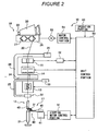
- the winder unit 10 shown in Figures 1 and 2 winds a yarn 20 unwound from a yarn supplying bobbin 21 while traversing the yarn 20, to form a package 30 with a predetermined length and a predetermined shape.
- An automatic winder according to the present embodiment comprises a plurality of the winder units 10 arranged in a line, and a machine frame control device (not shown) located at one end the arrangement of the winder units 10 in a direction in which the winder units 10 are arranged.
- Each of the winder units 10 comprises a unit frame 11 ( Figure 1 ) provided on one lateral side of the winder unit 10 in a front view, and a winding unit main body 16 provided on a side of the unit frame 11.
- the winding unit main body 16 comprises a cradle 23 configured to be able to hold the yarn supplying bobbin 22, and a winding drum 24 that traverses a yarn 20, while rotating the yarn winding bobbin 22.
- the cradle 23 is configured to be swingable in a direction in which the cradle 23 approaches or leaves the winding drum 24.
- the package 30 contacts with or leaves from the winding drum 24.
- a spiral traverse groove 27 is formed in an outer peripheral surface of the winding drum 24 so that the yarn 20 is traversed through the traverse groove 27.
- the cradle 23 comprises a liftup mechanism and a package brake mechanism (not shown).
- the liftup mechanism can elevate the cradle 23 to separate the package 30 from the winding drum 24.
- the package brake mechanism is configured to stop rotating the package 30 gripped by the cradle 23 at the same time when the cradle 23 is elevated by the liftup mechanism.
- the winding unit main body 16 is configured a balloon controller (unwinding assisting device) 12, a tensioning device 13, a splicer device 14 as a yarn splicing device, and a clearer 15 (yarn thickness detector) 15 are arranged in this order from the yarn supplying bobbin 21 side, in a yarn traveling route between the yarn supplying bobbin 21 and the winding drum 24.
- the winder unit 10 comprises a magazine-type supply device 60 that supplies the yarn supplying bobbin 21.
- the illustration of the magazine-type supply device 60 is omitted in order to illustrate the kink preventor 17 in detail.
- the magazine-type supply device 60 comprises a magazine holding portion 61 extending obliquely forward and upward from a lower portion of the winder unit 10, and a bobbin housing device 62 attached to a tip of the magazine holding portion 61.
- the bobbin housing device 62 comprises a magazine pocket 63 in which a plurality of housing holes are formed in a circle.
- a supplying bobbin 70 can be set in each of the housing holes in an inclined posture.
- the magazine pocket 63 can be intermittently drivingly fed by a motor (not shown). This intermittent driving and a control valve (not shown in the drawings) provided in the magazine pocket 63 enable the supplying bobbins 70 to be dropped one by one onto a bobbin supply path (not shown in the drawings) in the magazine holding portion 61.
- the supplying bobbin 70 supplied to the bobbin supply path is guided to the supplying bobbin holding portion 71 while remaining in the inclined posture.
- the supplying bobbin holding portion 71 comprises a pivotally moving means (not shown in the drawings).
- the supplying bobbin holding portion 71 thus pivotally move the supplying bobbin 70 received via the bobbin supply path so that the supplying bobbin 70 is raised from the inclined posture to an upright posture.
- the supplying bobbin 70 is appropriately supplied to the lower portion of the winding unit main body 16 as the yarn supplying bobbin 21.
- the winder unit 10 can then perform a winding operation.
- the balloon controller 12 lowers a regulating member 40 that covers a core tube of the yarn supplying bobbin 21, in conjunction with unwinding of the yarn from the yarn supplying bobbin 21.
- the balloon controller 12 thus assists in unwinding the yarn from the yarn supplying bobbin 21.
- the regulating member 40 contacts with a balloon formed above the yarn supplying bobbin 21 by the rotation and centrifugal force of the yarn 20 from the yarn supplying bobbin 21.
- the regulating member 40 thus applies the appropriate tension to the balloon to assist in unwinding the yarn 20.
- a sensor (not shown) is provided in the vicinity of the regulating member 40 to detect a chase portion of the yarn supplying bobbin 21. When the sensor detects that the chase portion is being lowered, then the regulating member 40 can be lowered in conjunction with the lowering of the chase portion by an air cylinder (not shown).
- a kink preventor 17 is located in the vicinity of the balloon controller 12 as a kink preventing device that prevents kink during a yarn splicing operation.
- the kink preventor 17 will be described below in detail.
- the tensioning device 13 applies a predetermined tension to the traveling yarn 20.
- the tensioning device 13 may be of, for example, a gate type having movable comb teeth arranged with respect to fixed comb teeth.
- the movable comb teeth can be pivotally moved by a rotary solenoid so as to be engaged with or released from the fixed comb teeth.
- the tensioning device 13 can apply the given tension to the yarn 20 being wound, to improve the quality of the package 30.
- the splicer device 14 splices a lower yarn on the yarn supplying bobbin 21 side and an upper yarn on the package 30 side.
- the splicer device 14 may be of a mechanical type or may use a fluid such as compressed air.
- the clearer 15 is configured to detect a defect by using an appropriate sensor to detect the thickness of the yarn 20.
- the clearer 15 unit is configured to be able to detect a yarn defect such as slab by allowing an analyzer 52 ( Figure 2 ) to process a signal from the sensor of the clearer 15.
- the clearer 15 can also function as a sensor that senses whether or not the yarn 20 is present.
- a cutter (not shown) is installed in the vicinity of the clearer 15 to immediately cut the yarn 20 when the clearer 15 detects a yarn defect.
- a first relay pipe 25 and a second relay pipe 26 are provided below and above the splicer device 14; the first relay pipe 25 catches and guides the lower yarn on the yarn supplying bobbin 21 side, and the second relay pipe 26 catches and guides the upper yarn on the package 30 side.
- a suction port 32 is formed at a tip of the first relay pipe 25, and a suction mouth 34 is provided at a tip of the second relay pipe 26.
- An appropriate negative pressure source is connected to each of the two relay pipes 25, 26 to enable suction flows to be generated at the suction port 32 and the suction mouth 34.
- the suction port 32 of the first relay pipe 25 catches the lower yarn at a position shown in Figures 1 and 2 .
- the first relay pipe 25 then pivotally moves upward around a shaft 33 to guide the lower yarn to the splicer device 14.
- the second relay pipe 26 pivotally moves upward from an illustrated position around a shaft 35.
- the suction mouth 34 thus catches the upper yarn present on a surface of the package 30 reversed by a drum driving motor 53.
- the second relay pipe 26 subsequently moves pivotally downward around the shaft to guide the upper yarn to the splicer device 14.
- the yarn 20 unwound from the yarn supplying bobbin 21 is wound around the yarn winding bobbin 22, located on a downstream side of the splicer device 14.
- the yarn winding bobbin 22 is driven by rotationally driving the winding drum 24, located opposite the yarn winding bobbin 22.
- the winding drum 24 is coupled to an output shaft of the drum driving motor 53.
- the operation of the drum driving motor 53 is controlled by a motor control portion 54.
- the motor control portion 54 is configured so as to controllably operate and stop the drum driving motor 53 in response to an operation signal from the unit control portion 50.
- the yarn winding bobbin 22 is driven to wind the yarn 20 unwound from the yarn supplying bobbin 21 around the yarn winding bobbin 22.
- the package 30 of a predetermined length can thus be formed.
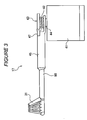
- Figure 3 is a side view showing the kink preventor 17.
- Figure 4 is a plan view showing a standby state of the kink preventor 17.
- the kink preventor 17 comprises a contact portion 80 that contacts with the yarn supplying bobbin 21 to apply a given tension to the yarn 20, and a stepping motor 41 that pivotally moves the contact portion 80.
- the contact portion 80 comprises a pivotally moving arm 45 and a brush portion 31 provided at a tip portion of the pivotally moving arm 45.
- the brush portion 31 comprises a large number of bristles arranged in a circular arc.
- the bristles have appropriate elasticity and are arranged so that the tips of the bristles face obliquely upward.
- the tips of the bristles approach an upper portion of the core tube of the yarn supplying bobbin 21 while being appropriately deformed.
- the tips of the bristles at least a part of an outer peripheral surface of the upper part of the core tube.
- the force exerted by the brush portion 31 to press the upper portion of the core tube of the yarn supplying bobbin 21 is adjusted so as to prevent the yarn 20 from being drawn out from the yarn supplying bobbin 21 by the suction force of the relay pipe 25, into which the yarn end is sucked. Furthermore, the force exerted by the brush portion 31 to press the upper portion of the core tube of the yarn supplying bobbin 21 is adjusted so as to be minimized while still enabling prevention of excessive drawout of the yarn 20 from the yarn supplying bobbin 21 and thus prevention of kink.
- Such adjustment of the pressing force can also be precisely achieved by the stepping motor 41.
- An output shaft 44 that is a shaft portion of the stepping motor 41 is located in a vertical direction and includes a tip projecting upward.
- An insertion hole (not shown) is formed at a base end portion of the pivotally moving arm 45 so that the output shaft 44 of the stepping motor 41 can be inserted through the insertion hole.
- the pivotally moving arm 45 is rotatable relative to the output shaft 44 of the stepping motor 41.
- a pivotally moving portion 43 is fixed to a tip portion of the output shaft 44 of the stepping motor 41.
- the pivotally moving portion 43 is configured to rotate integrally with the output shaft 44.
- a stopper 47 is protrusively formed integrally with the pivotally moving portion 43.
- the stopper 47 is configured to be able to abut against a side surface of the pivotally moving arm 45.
- the kink preventor 17 comprises a torsion spring 42 that elastically couples the pivotally moving portion 43 and the pivotally moving arm 45 together.
- the output shaft 44 is inserted through a coil portion of the torsion spring 42.
- the stepping motor 41 is connected to a stepping motor control portion 51.
- the stepping motor control portion 51 outputs a driving pulse signal to the stepping motor 41 to drive the stepping motor 41.
- the stepping motor control portion 51 is connected to the unit control portion 50 to enable the kink preventor 17 to be controlled in conjunction with the control of the splicer device 14, the clearer 15, the balloon controller 12, and other portions.
- the automatic winder comprises an operation portion 90 to which the unit control portion 50 is connected.
- An operator can operate the operation portion 90 to set the rotation angle (in other words, the pressing force exerted on the yarn supplying bobbin 21 by the contact portion 80) of the stepping motor 41 by, for example, inputting a value for the angle; on the basis of the rotation angle, the pivotally moving arm 45 presses the yarn supplying bobbin 21 to prevent kink in the yarn 20.
- the operation portion 90 is provided in each of the winder units 10.
- the rotation angle of the stepping motor 41 can be adjusted for the kink preventors 17 in the required units alone.
- the operation portion may be provided in the machine frame control device, which integrally manages the plurality of winder units 10. In this case, by allowing the operation portion to individually adjust the kink preventors 17 in the appropriate units, the kink preventors 17 in the required units alone can be adjusted as described above.
- Figure 5 is a plan view showing that the brush portion 31 of the kink preventor 17 is in contact with the yarn supplying bobbin 21.
- Figure 6 is a perspective view showing that the yarn 20 is unwound from the yarn supplying bobbin 21 with the brush portion 31 pressed against the yarn supplying bobbin 31.
- the stepping motor control portion 51 controls the stepping motor 41 to bring the pivotally moving portion 43 to rest at a position shown in Figure 4 .
- the action of the torsion spring 42 brings the pivotally moving arm 45 to rest in contact with the stopper 47 of the pivotally moving portion 43.
- the contact portion 80 is placed in a standby position shown in Figure 4 .
- the brush portion 31 of the pivotally moving arm 45 is sufficiently separated from the yarn supplying bobbin 21 instead of contacting with the yarn supplying bobbin 21. Consequently, when the regulating member 40 of the balloon controller 12 is moved to control the balloon, the pivotally moving arm 45 and the like are prevented from obstructing the movement.
- the unit control portion 50 retracts the regulating member 40 of the balloon controller 12 upward and then transmits an operation signal to the stepping motor control portion 51.
- the stepping motor control portion 51 transmits a driving pulse signal to the stepping motor 41.
- the stepping motor 41 rotates the output shaft 44 through an angle corresponding to the number of pulses to pivotally move the pivotally moving portion 43.
- the rotation angle of the stepping motor 41 is set via the operation portion 90.
- the pivotally moving arm 45 coupled to the pivotally moving portion 43 via the torsion spring 42, moves pivotally in conjunction with the pivotal movement of the pivotally moving portion 43.
- Figure 5 shows a contact state in which the pivotally moving portion 43 is further pivotally moved through an angle A after the brush portion 31 of the pivotally moving arm 45 has come into contact with the yarn supplying bobbin 21.
- the spring force of the torsion spring 42 presses the pivotally moving arm 45 against the yarn supplying bobbin 21 to contact the brush portion 31 with the core tube at the upper end of the yarn supplying bobbin 21.
- the first relay pipe 25 catches and guides the yarn on the yarn supplying bobbin 21 side to the splicer device 14 for the yarn splicing operation
- an appropriate tension is applied to the yarn 20 unwound from the yarn supplying bobbin 21 to prevent kink.
- the appropriate tension is applied to the yarn 20 unwound from the yarn supplying bobbin 21 to adjust the amount of yarn 20 unwound from the yarn supplying bobbin 21 so as to prevent an excessive amount of yarn 20 from being unwound. This in turn prevents the yarn 20 from being wasted.
- the force exerted by the brush portion 31 to press the yarn supplying bobbin 21 increases consistently with the pivotal movement angle (above-described angle A) of the pivotally moving portion 43 after the contact portion 80 has come into contact with the yarn supplying bobbin 21.
- the kink preventor 17 allows the set value of the rotation angle of the stepping motor 41 to be varied via the operation portion 90. Consequently, the pressing force (or the tension applied to the unwound yarn) exerted on the yarn supplying bobbin 21 by the brush portion 31 can be easily adjusted.
- the automatic winder winds a yarn type with a smaller diameter
- possible yarn breakage can be prevented by adjustably reducing the rotation angle of the stepping motor 41.
- the yarn splicing operation can be smoothly performed by adjustably increasing the rotation angle of the stepping motor 41.
- the pressing force exerted on the yarn supplying bobbin 21 by the brush portion 31 is adjusted so as to prevent the yarn 20 from being drawn out from the yarn supplying bobbin 21 by the suction port 32 in the relay pipe 25. This enables a reduction in the yarn 20 uselessly drawn out from the yarn supplying bobbin 21.
- the pressing force of the pivotally moving arm 45 can be recovered to allow the appropriate tension to be applied to the yarn 20, by controlling the rotation angle of the stepping motor 41 so that the angle A is correspondingly increased. Consequently, replacement of the torsion spring 42 and complicated adjustment operations can be omitted.
- the pivotal movement angle of the pivotally moving portion 43 can be precisely adjusted by changing the number of pulses transmitted to the stepping motor 41. Consequently, the tension of the yarn 20 unwound from the yarn supplying bobbin 21 can be easily fine-tuned.
- the pressing force of the contact portion 80 can be electrically varied without the need for a change in mechanical arrangement such as replacement of the torsion spring 42.
- the automatic winder can be easily configured such that for example, the pressing force can be adjusted while the automatic winder is in operation.
- the kink preventor 17 is configured so as to contact with at least a part of the yarn supplying bobbin 21 to tense the yarn 20 being unwound, to prevent kink. Furthermore, the kink preventor 17 comprises the contact portion 80, which can contact with the yarn supplying bobbin 21, and the stepping motor 41, which moves the contact portion 80.
- the stepping motor 41 which can accurately control the rotation angle, can be used to precisely control the pressing of the contact portion against the yarn supplying bobbin 21. Furthermore, since varying the rotation angle of the stepping motor 41 enables adjustment of the pressing force exerted on the yarn supplying bobbin 21 by the contact portion 80, the operation of adjusting the tension of the yarn 20 during the yarn splicing operation is facilitated. Operational efficiency is thus improved.
- the kink preventor 17 comprises the output shaft 44, to which the rotation of the stepping motor 41 is transmitted, the pivotally moving portion 43, which is attached to the output shaft 44 to rotate integrally with the output shaft 44, and the torsion spring 42, provided between the pivotally moving portion 43 and the contact portion 80.
- the contact portion 80 is rotatably attached to the output shaft 44.
- the stepping motor 41 pivotally moves the pivotally moving portion 43 to allow the contact portion 80 to be pivotally moved by the biasing force of the torsion spring 42.
- the pivotally moving portion 43 moves pivotally to deform the torsion spring 42.
- the spring force of the torsion spring 42 then acts to restore the original state thereof.
- the contact portion 80 can thus be stably pressed against the yarn supplying bobbin 21.
- the deformation amount of the torsion spring 42 can be adjusted to precisely and easily control the force pressing the contact portion 80 against the yarn supplying bobbin 21.
- the pivotally moving potion 43 and the contact portion 80 are connected together via the torsion spring 42.
- This arrangement enables provision of a simple and compact configuration in which the pivotally moving portion 43 moves pivotally to allow the pressing force exerted on the yarn supplying bobbin 21 by the contact portion 80 to be adjusted.
- the kink preventor 17 comprises the stepping motor control portion 51, which is configured to control the stepping motor 41 so that the contact portion 80 contacts with the yarn supplying bobbin 21. Furthermore, the stepping motor control portion 51 can vary the rotation angle of the stepping motor 41, on the basis of which the contact portion 80 is pressed against the yarn supplying bobbin 21.
- the stepping motor control portion 51 can be utilized to electrically adjust the rotation angle of the stepping motor 41 to allow the pressing force to be easily adjusted.
- the contact portion 80 comprises the brush portion 31, which can contact with the yarn supplying bobbin 21.
- the pivotally moving portion 43 as a separate component is fixed to the output shaft 44 of the stepping motor 41.
- the configuration can be changed such that the output shaft 44 of the stepping motor 41 is processed to form the pivotally moving portion integrally with the output shaft 44.
- the configuration can be changed such that the pivotall moving portion 43 and the contact portion 80 (pivotally moving arm 45) are connected together via an elastic body such as any of various springs such as a tension spring and a leaf spring or rubber instead of the torsion spring 42.
- an elastic body such as any of various springs such as a tension spring and a leaf spring or rubber instead of the torsion spring 42.
- the brush portion 31, provided in the contact portion 80 in the above-described embodiment, may be omitted.
- the configuration can be changed such that for example, the pivotally moving arm 45 directly presses the yarn supplying bobbin 21.
- the above-described embodiment is configured such that the rotation angle of the stepping motor 41 (the pivotal movement angle of the pivotally moving portion 43) is set by inputting a numerical value directly via the operation portion 90.
- the configuration can be changed such that rotation angles corresponding to yarn types are stored in the unit control portion 50 or the like so that one of the yarn types displayed on the operation portion 90 is selected to allow a number of driving pulses corresponding to the stored angle are transmitted to the stepping motor 41.
- the winder unit 10 uses the magazine type supply device 60 to supply the yarn supplying bobbin 21.
- the present invention is not limited to this configuration.
- the configuration can be changed such that for example, the yarn supplying bobbin 21 is supplied to the winder unit 10 by conveying a tray with the yarn supplying bobbin 21 set thereon along an appropriate path.
Landscapes
- Engineering & Computer Science (AREA)
- Quality & Reliability (AREA)
- Replacing, Conveying, And Pick-Finding For Filamentary Materials (AREA)
- Winding Filamentary Materials (AREA)
- Forwarding And Storing Of Filamentary Material (AREA)
- Unwinding Of Filamentary Materials (AREA)
- Tension Adjustment In Filamentary Materials (AREA)
Claims (5)
- Dispositif anti-vrille (17) qui entre en contact avec au moins une partie d'une bobine d'alimentation en fil (21) pour appliquer une tension à un fil déroulé de la bobine d'alimentation en fil (21) afin d'empêcher des vrilles, le dispositif (17) comprenant une partie de contact (80) qui peut entrer en contact avec la bobine d'alimentation en fil (21),
caractérisé en ce que
le dispositif comprend un moteur pas à pas (41) qui déplace la partie de contact (80), une partie arbre (44) à laquelle la rotation du moteur pas à pas (41) est transmise, une partie à déplacement par pivotement (43) fixée à la partie arbre (44) et qui tourne d'une seule pièce avec la partie arbre (44), et une partie ressort (42) prévue entre la partie à déplacement par pivotement (43) et la partie de contact (80), et en ce que la partie de contact (80) est fixée de manière amovible par pivotement à la partie arbre (44), et le moteur pas à pas (41) déplace par pivotement la partie à déplacement par pivotement (43) pour permettre à la partie de contact (80) de se déplacer par pivotement sous l'action d'une force de sollicitation de la partie ressort (42). - Dispositif anti-vrille (17) selon la revendication 1, caractérisé en ce que la partie ressort (42) est un ressort de torsion.
- Dispositif anti-vrille (17) selon la revendication 1 ou 2, caractérisé en ce qu'il comprend une partie de commande (51) qui commande le moteur pas à pas (41) de sorte que la partie de contact (80) soit mise en contact avec la bobine d'alimentation en fil (21) et qui peut modifier l'angle de rotation du moteur pas à pas (41), ce qui fait que la partie de contact (80) est pressée contre la bobine d'alimentation en fil (21).
- Dispositif anti-vrille (17) selon l'une quelconque des revendications 1 à 3, caractérisé en ce que la partie de contact (80) comprend une partie brosse (31) qui peut entrer en contact avec la bobine d'alimentation en fil (21).
- Enrouleur automatique comprenant le dispositif anti-vrille (17) selon l'une quelconque des revendications 1 à 4.
Applications Claiming Priority (1)
| Application Number | Priority Date | Filing Date | Title |
|---|---|---|---|
| JP2008002027A JP2009161327A (ja) | 2008-01-09 | 2008-01-09 | ビリ防止装置及びそれを備える自動ワインダ |
Publications (3)
| Publication Number | Publication Date |
|---|---|
| EP2078691A2 EP2078691A2 (fr) | 2009-07-15 |
| EP2078691A3 EP2078691A3 (fr) | 2009-12-09 |
| EP2078691B1 true EP2078691B1 (fr) | 2011-07-06 |
Family
ID=40497557
Family Applications (1)
| Application Number | Title | Priority Date | Filing Date |
|---|---|---|---|
| EP20080020337 Ceased EP2078691B1 (fr) | 2008-01-09 | 2008-11-21 | Dispositif anti-tortillement et enrouleur automatique le comportant |
Country Status (3)
| Country | Link |
|---|---|
| EP (1) | EP2078691B1 (fr) |
| JP (1) | JP2009161327A (fr) |
| CN (1) | CN101481056B (fr) |
Families Citing this family (4)
| Publication number | Priority date | Publication date | Assignee | Title |
|---|---|---|---|---|
| JP2009203008A (ja) * | 2008-02-28 | 2009-09-10 | Murata Mach Ltd | 糸巻取装置と、これを備えた繊維機械 |
| IT201800005658A1 (it) * | 2018-05-24 | 2019-11-24 | Unità di roccatura munita di dispositivo antiriccio perfezionato e metodo di captazione di un bandolo di filo di una spola a seguito di taglio, in un’unità di roccatura | |
| DE102019107378A1 (de) * | 2019-03-22 | 2020-09-24 | Saurer Spinning Solutions Gmbh & Co. Kg | Verfahren zur Kopsvorbereitung |
| JP7425695B2 (ja) | 2019-07-30 | 2024-01-31 | Tmtマシナリー株式会社 | 合繊糸用糸継システム |
Family Cites Families (7)
| Publication number | Priority date | Publication date | Assignee | Title |
|---|---|---|---|---|
| JPH0158573U (fr) * | 1987-10-08 | 1989-04-12 | ||
| JPH078532Y2 (ja) * | 1989-01-25 | 1995-03-01 | 村田機械株式会社 | ワインダのビリ防止装置 |
| JPH03127665U (fr) * | 1990-04-10 | 1991-12-24 | ||
| US5377923A (en) * | 1991-07-01 | 1995-01-03 | Murata Kikai Kabushiki Kaisha | Yarn unwinding assisting device and yarn unwinding method in an automatic winder |
| JPH0811666B2 (ja) * | 1991-09-19 | 1996-02-07 | 村田機械株式会社 | 自動ワインダの解舒補助装置 |
| JP3218505B2 (ja) | 1997-07-28 | 2001-10-15 | 村田機械株式会社 | 自動ワインダーにおけるビリ防止方法 |
| JP2007290839A (ja) * | 2006-04-27 | 2007-11-08 | Murata Mach Ltd | 巻き終わり糸の制御装置 |
-
2008
- 2008-01-09 JP JP2008002027A patent/JP2009161327A/ja active Pending
- 2008-11-21 EP EP20080020337 patent/EP2078691B1/fr not_active Ceased
- 2008-12-09 CN CN2008101838294A patent/CN101481056B/zh active Active
Also Published As
| Publication number | Publication date |
|---|---|
| EP2078691A3 (fr) | 2009-12-09 |
| EP2078691A2 (fr) | 2009-07-15 |
| CN101481056A (zh) | 2009-07-15 |
| CN101481056B (zh) | 2012-08-22 |
| JP2009161327A (ja) | 2009-07-23 |
Similar Documents
| Publication | Publication Date | Title |
|---|---|---|
| EP2377793B1 (fr) | Dispositif de bobinage de fil et enrouleur automatique | |
| EP2105398A2 (fr) | Appareil renvideur de fil | |
| EP2511216B2 (fr) | Appareil d'enroulement de fil et procédé de retrait de fil | |
| EP2157039B1 (fr) | Machine textile | |
| EP2202192B1 (fr) | Dispositif de bobinage de fil et enrouleur automatique | |
| CN101837909B (zh) | 操作制造交叉卷绕筒子的纺织机的工位的方法和装置以及执行该方法的工位 | |
| JP5545593B2 (ja) | 糸巻取機 | |
| CN107777472B (zh) | 用于制造交叉卷绕筒子的纺织机的工位的接纱装置 | |
| EP2072440B1 (fr) | Dispositif d'assistance de déroulement et méthode pour faire fonctionner un dispositif d'assistance de déroulement | |
| EP2078691B1 (fr) | Dispositif anti-tortillement et enrouleur automatique le comportant | |
| JP4531906B2 (ja) | 綾巻パッケージを巻成する繊維機械の1作業ユニットを運転する方法 | |
| WO2020075382A1 (fr) | Bobineuse de fil | |
| JP2009286608A (ja) | 自動ワインダ | |
| EP1457446B9 (fr) | Dispositif de réglage de tension et d'élimination des relâchements de fil pour un dispositif de bobinage | |
| CN113201828A (zh) | 接头装置、卷取单元以及纱线卷取机 | |
| JP2010037083A (ja) | 糸巻取機及び自動ワインダ | |
| JP2009155101A (ja) | 巻取ユニット及びそれを備える自動ワインダ | |
| CN107963512B (zh) | 纱线卷取装置以及卷装的旋转停止方法 | |
| WO2015029292A1 (fr) | Dispositif tendeur de fil | |
| EP3686142B1 (fr) | Dispositif d'assemblage de fil et dispositif de bobinage de fil | |
| EP3159293B1 (fr) | Dispositif de bobinage de fil | |
| EP1561717B1 (fr) | Métier à filer avec un dispositif pour bobiner d'une réserve de fil sur une bobine vide | |
| JP2013249160A (ja) | パッケージ排出装置および糸巻取機 | |
| EP4112521A1 (fr) | Machine d'enroulement de fil | |
| EP3159294B1 (fr) | Dispositif de bobinage de fil |
Legal Events
| Date | Code | Title | Description |
|---|---|---|---|
| PUAI | Public reference made under article 153(3) epc to a published international application that has entered the european phase |
Free format text: ORIGINAL CODE: 0009012 |
|
| AK | Designated contracting states |
Kind code of ref document: A2 Designated state(s): AT BE BG CH CY CZ DE DK EE ES FI FR GB GR HR HU IE IS IT LI LT LU LV MC MT NL NO PL PT RO SE SI SK TR |
|
| AX | Request for extension of the european patent |
Extension state: AL BA MK RS |
|
| PUAL | Search report despatched |
Free format text: ORIGINAL CODE: 0009013 |
|
| AK | Designated contracting states |
Kind code of ref document: A3 Designated state(s): AT BE BG CH CY CZ DE DK EE ES FI FR GB GR HR HU IE IS IT LI LT LU LV MC MT NL NO PL PT RO SE SI SK TR |
|
| AX | Request for extension of the european patent |
Extension state: AL BA MK RS |
|
| 17P | Request for examination filed |
Effective date: 20100608 |
|
| AKX | Designation fees paid |
Designated state(s): DE IT |
|
| RIC1 | Information provided on ipc code assigned before grant |
Ipc: B65H 63/08 20060101ALI20110117BHEP Ipc: B65H 59/06 20060101AFI20110117BHEP |
|
| GRAP | Despatch of communication of intention to grant a patent |
Free format text: ORIGINAL CODE: EPIDOSNIGR1 |
|
| GRAS | Grant fee paid |
Free format text: ORIGINAL CODE: EPIDOSNIGR3 |
|
| GRAA | (expected) grant |
Free format text: ORIGINAL CODE: 0009210 |
|
| AK | Designated contracting states |
Kind code of ref document: B1 Designated state(s): DE IT |
|
| REG | Reference to a national code |
Ref country code: DE Ref legal event code: R096 Ref document number: 602008008046 Country of ref document: DE Effective date: 20110825 |
|
| PLBE | No opposition filed within time limit |
Free format text: ORIGINAL CODE: 0009261 |
|
| STAA | Information on the status of an ep patent application or granted ep patent |
Free format text: STATUS: NO OPPOSITION FILED WITHIN TIME LIMIT |
|
| 26N | No opposition filed |
Effective date: 20120411 |
|
| REG | Reference to a national code |
Ref country code: DE Ref legal event code: R097 Ref document number: 602008008046 Country of ref document: DE Effective date: 20120411 |
|
| PGFP | Annual fee paid to national office [announced via postgrant information from national office to epo] |
Ref country code: IT Payment date: 20201124 Year of fee payment: 13 Ref country code: DE Payment date: 20201119 Year of fee payment: 13 |
|
| REG | Reference to a national code |
Ref country code: DE Ref legal event code: R119 Ref document number: 602008008046 Country of ref document: DE |
|
| PG25 | Lapsed in a contracting state [announced via postgrant information from national office to epo] |
Ref country code: DE Free format text: LAPSE BECAUSE OF NON-PAYMENT OF DUE FEES Effective date: 20220601 |
|
| PG25 | Lapsed in a contracting state [announced via postgrant information from national office to epo] |
Ref country code: IT Free format text: LAPSE BECAUSE OF NON-PAYMENT OF DUE FEES Effective date: 20211121 |