EP2077456B1 - Ultrasound system and method of providing ultrasound images - Google Patents
Ultrasound system and method of providing ultrasound images Download PDFInfo
- Publication number
- EP2077456B1 EP2077456B1 EP08022094.0A EP08022094A EP2077456B1 EP 2077456 B1 EP2077456 B1 EP 2077456B1 EP 08022094 A EP08022094 A EP 08022094A EP 2077456 B1 EP2077456 B1 EP 2077456B1
- Authority
- EP
- European Patent Office
- Prior art keywords
- gap
- mode image
- edge points
- ultrasound
- degree polynomial
- Prior art date
- Legal status (The legal status is an assumption and is not a legal conclusion. Google has not performed a legal analysis and makes no representation as to the accuracy of the status listed.)
- Not-in-force
Links
Images


Classifications
-
- G—PHYSICS
- G01—MEASURING; TESTING
- G01S—RADIO DIRECTION-FINDING; RADIO NAVIGATION; DETERMINING DISTANCE OR VELOCITY BY USE OF RADIO WAVES; LOCATING OR PRESENCE-DETECTING BY USE OF THE REFLECTION OR RERADIATION OF RADIO WAVES; ANALOGOUS ARRANGEMENTS USING OTHER WAVES
- G01S15/00—Systems using the reflection or reradiation of acoustic waves, e.g. sonar systems
- G01S15/88—Sonar systems specially adapted for specific applications
- G01S15/89—Sonar systems specially adapted for specific applications for mapping or imaging
- G01S15/8906—Short-range imaging systems; Acoustic microscope systems using pulse-echo techniques
- G01S15/8979—Combined Doppler and pulse-echo imaging systems
-
- A—HUMAN NECESSITIES
- A61—MEDICAL OR VETERINARY SCIENCE; HYGIENE
- A61B—DIAGNOSIS; SURGERY; IDENTIFICATION
- A61B8/00—Diagnosis using ultrasonic, sonic or infrasonic waves
-
- G—PHYSICS
- G01—MEASURING; TESTING
- G01S—RADIO DIRECTION-FINDING; RADIO NAVIGATION; DETERMINING DISTANCE OR VELOCITY BY USE OF RADIO WAVES; LOCATING OR PRESENCE-DETECTING BY USE OF THE REFLECTION OR RERADIATION OF RADIO WAVES; ANALOGOUS ARRANGEMENTS USING OTHER WAVES
- G01S7/00—Details of systems according to groups G01S13/00, G01S15/00, G01S17/00
- G01S7/52—Details of systems according to groups G01S13/00, G01S15/00, G01S17/00 of systems according to group G01S15/00
- G01S7/52017—Details of systems according to groups G01S13/00, G01S15/00, G01S17/00 of systems according to group G01S15/00 particularly adapted to short-range imaging
- G01S7/52023—Details of receivers
- G01S7/52034—Data rate converters
-
- G—PHYSICS
- G01—MEASURING; TESTING
- G01S—RADIO DIRECTION-FINDING; RADIO NAVIGATION; DETERMINING DISTANCE OR VELOCITY BY USE OF RADIO WAVES; LOCATING OR PRESENCE-DETECTING BY USE OF THE REFLECTION OR RERADIATION OF RADIO WAVES; ANALOGOUS ARRANGEMENTS USING OTHER WAVES
- G01S7/00—Details of systems according to groups G01S13/00, G01S15/00, G01S17/00
- G01S7/52—Details of systems according to groups G01S13/00, G01S15/00, G01S17/00 of systems according to group G01S15/00
- G01S7/52017—Details of systems according to groups G01S13/00, G01S15/00, G01S17/00 of systems according to group G01S15/00 particularly adapted to short-range imaging
- G01S7/52085—Details related to the ultrasound signal acquisition, e.g. scan sequences
Definitions
- the present invention generally relates to ultrasound systems, and more particularly to an ultrasound system and a method of providing ultrasound images in a duplex mode.
- An ultrasound system has become an important and popular diagnostic tool due to its non-invasive and non-destructive nature.
- Modern high-performance ultrasound imaging diagnostic devices and techniques are commonly used to produce two- or three-dimensional images of internal features of patients.
- the ultrasound system operates in a duplex mode for simultaneously providing ultrasound images in two or more diagnostic modes.
- the ultrasound system may provide a BD-mode image with a blood flow or movement of a target object indicated.
- the BD-mode is a diagnostic mode for providing a brightness (B)-mode image and a Doppler (D)-mode image at the same time.
- the D-mode image may include a spectral Doppler image formed based on Doppler signals, which are obtained from a sample volume set on the B-mode image.
- the D-mode image may indicate information regarding the moving direction and velocity of a blood flow or moving object.
- a horizontal axis may represent time while a vertical axis represents velocity (or frequency).
- the ultrasound system may alternately transmit a first ultrasound beam for obtaining the B-mode image and a second ultrasound beam for obtaining the D-mode image.
- the second ultrasound beam may not be transmitted while the first ultrasound beam is transmitted in the BD-mode.
- a pulse repetition frequency (PRF) for the second ultrasound pulse may increase.
- PRF pulse repetition frequency
- a velocity scale in the spectral Doppler image may be lowered so that a detectable maximum velocity of a blood flow may be decreased.
- the first ultrasound beam may be transmitted for a first predetermined time duration.
- the second ultrasound pulse may be transmitted for a second predetermined time duration. In such a case, however, the second ultrasound beam may not be transmitted for the first predetermined time duration for transmitting the first ultrasound beam.
- a gap corresponding to the first predetermined time duration may occur in the D-mode image.
- a method and a system for processing Doppler signal gaps is disclosed in US 2007/049823 A1 .
- the method comprises the steps of receiving Doppler signals during Doppler signal acquisition to obtain data of in-phase component and quadrate component signals of the Doppler signals, receiving interruption of the Doppler signals, estimating the data of the Doppler signals interrupted in said gap period, filling the interrupted Doppler signals with the data of the estimated Doppler signals so that the data of the I and Q component signals in said gap period are filled to form a continuous output, and generating Doppler spectrum data or Doppler sound based on the data of the filled I and Q component signals.
- the ultrasonic imaging apparatus comprises an ultrasonic transducer for emitting ultrasonic pulses at a rate frequency fr and converting an echo wave of the ultrasonic pulses into an echo signal, an orthogonal detector circuit for orthogonally detecting an echo signal provided from the ultrasonic transducer and a calculator circuit for obtaining Doppler data from the orthogonal detection signal and providing color Doppler data.
- the output of the calculator circuit is coupled to an interpolator circuit.
- the interpolator circuit When the interpolator circuit receives color Doppler data at a frequency above + fr/2 or -fr/2 from the calculator circuit, it interpolates the Doppler data according to a predetermined argorithm for excluding interpolation data corresponding to a zero region between +fr/2 and -fr/2.
- the color Doppler data including interpolation data is displayed as color image on the monitor.
- FIG. 1 is a block diagram showing an ultrasound system in accordance with one example of the present invention.
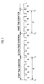
- FIG. 2 is a timing diagram showing an example of alternately transmitting a first ultrasound beam and a second ultrasound beam in a duplex mode.
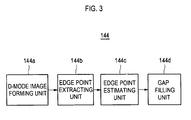
- FIG. 3 is a block diagram showing a D-mode image processing unit in accordance with one example of the present invention.
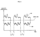
- FIG. 4 is a schematic diagram showing an example of a D-mode image.
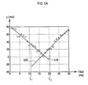
- FIG. 5A is a graph showing examples of first degree polynomial curves.
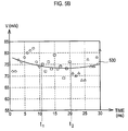
- FIG. 5B is a graph showing an example of a second degree polynomial curve.
- FIG. 6 is a schematic diagram illustrating an example of gap filling.
- FIG. 1 is a block diagram showing an ultrasound system in accordance with one example of the present invention.
- the ultrasound system 100 may include a user input unit 110 allowing a user to input instructions.
- the instructions may include a setup instruction for setting a sample volume on a B-mode image.
- the setup instruction may include information about the position and size of the sample volume.
- the input unit 110 may be an arbitrary input device such as a mouse, a keyboard, a track ball, etc.
- the ultrasound system 100 may further include a transmission/reception unit 120 configured to generate ultrasound beams.
- the ultrasound beams may be transmitted to a target object.
- the transmission/reception unit 120 may be further configured to convert ultrasound echoes reflected from a target object into electrical receive signals.
- the ultrasound system 100 may further include a control unit 110 configured to generate control signals for controlling the generation of ultrasound beams in the transmission/reception unit 110.
- the control signals may include a first control signal for controlling the generation of an ultrasound beam for obtaining a B-mode image ("first ultrasound beam”).
- the control signals may further include a second control signal for controlling the generation of an ultrasound beam for obtaining a D-mode image ("second ultrasound beam”).
- the second control signal may be generated based on the setup instruction inputted through the user input unit 110.
- the first ultrasound beam is transmitted for obtaining the B-mode image in one example, the obtainable image is not limited to the B-mode image.
- a motion mode image or a color mode image may be obtained based on the first ultrasound beam.
- the control unit 130 may generate the control signals such that the first ultrasound beam is transmitted for a predetermined time duration ("first time duration”) and the second ultrasound beam is transmitted for a predetermined time duration ("second time duration”), as illustrated in FIG. 2 .
- first time duration a predetermined time duration
- second time duration a predetermined time duration
- a symbol "G" in FIG. 2 may represent a gap corresponding to the first time duration t 1 -t 2 or t 3 -t 4 in the D-mode image.
- the transmission/reception unit 110 may be configured to transmit the first ultrasound beam to the target object in response to the first control signal and form receive signals based on ultrasound echoes reflected from the target object. Also, the transmission/reception unit 110 may transmit the second ultrasound beam to the sample volume in response to the second control signal and form spectral Doppler signals based on ultrasound echoes reflected from the sample volume.
- the ultrasound system 100 may further include an image processing unit 140.
- the image processing unit 140 may include a B-mode image processing unit 142 and a D-mode image processing unit 144.
- the B-mode image processing unit 142 may be configured to form a B-mode image based on the receive signals.
- the D-mode image processing unit 144 may form a D-mode image (i.e., spectral Doppler image) based on the spectral Doppler signals.
- the D-mode image processing unit 144 may be further configured to extract edge points from the D-mode image and estimate edge points at a gap corresponding to the first time duration in the D-mode image.
- the D-mode image processing unit 144 may perform gap filling for the gap based on the estimated edge points.
- FIG. 3 is a block diagram showing an example of the D-mode image processing unit 144.
- the D-mode image processing unit 144 may include a D-mode image forming unit 144a, an edge point extracting unit 144b, an edge point estimating unit 144c and a gap filling unit 144d.
- the D-mode image forming unit 144a may be configured to form a D-mode image containing gaps G occurring when transmitting the first ultrasound beam for the first time duration, as illustrated in FIG. 4 .
- a horizontal axis may represent time and a vertical axis may represent velocity (or frequency).
- the edge point extracting unit 144b may extract edge points from the D-mode image.
- the edge points may be extracted based on a variation of brightness values determined by a differential operator.
- the edge points may be extracted by using an edge mask such as Sobel, Prewitt, Robert, Laplacian of Gaussian, Canny, etc.
- the edge point extracting unit 144b may extract first edge points of Doppler spectra having a greater scale than a base line scale ("upper Doppler spectra 210") on the velocity axis from the D-mode image.
- the edge point extracting unit 144b may be configured to extract second edge points of Doppler spectra having a less scale than a base line scale ("lower Doppler spectra 220") on the velocity axis from the D-mode image. Some first and second edge points may exist on an identical straight line perpendicular to the base line.
- the edge point estimating unit 144c may be configured to compute a polynomial curve of the extracted edge points to thereby estimate edge points within the gap.
- the edge point estimating unit 144c may compute a first degree polynomial curve 510 by using first edge points (denoted by a circle) positioned at a left side of the gap G, i.e., prior to the gap G.
- the edge point estimating unit 114c may be further configured to compute a first degree polynomial curve 520 by using first edge points (denoted by a triangle) positioned at a right side of the gap G, i.e., posterior to the gap G.
- the edge point estimating unit 114c may check whether two first degree polynomial curves 510 and 520 intersect.
- the edge point estimating unit 144c may compute a variance of the first edge points prior to the gap G and a variance of the first edge points posterior to the gap G.
- the edge point estimating unit 144c may estimate the first edge points (denoted by rectangle) within the gap G based on the computed variances and two first degree polynomial curves 510 and 320, as shown in FIG. 5A .
- the edge point estimating unit 144c may compute a second degree polynomial curve 530 by using the first edge points (denoted by a circle) prior to the gap G and the first edge points (denoted by a triangle) posterior to the gap G and variance of the first edge points, as illustrated in FIG. 5B .
- the edge point estimating unit 144c may estimate the first edge points (denoted by a rectangle) within the gap G based on the computed variance and the second degree polynomial curve 330.
- the edge point estimating unit 144c may be further configured to estimate the second edge points for the lower Doppler spectra within the gap G in the same manner as the first edge points.
- the gap filling unit 144d may be configured to perform gap filling based on the estimated edge points within the gap G and Doppler spectra neighboring the gap G.
- the gap filling unit 144d may use a linear interpolation method for the gap filling.
- the gap filling unit 144d may perform gap filling for a gap 400 by linearly interpolating the first estimated edge points and the second estimated edge points starting from the Doppler spectra 410 and 420 prior to the gap G ("forward gap filling"), thereby forming a D-mode image with the gap filled.
- the gap filling unit 144d may perform gap filling for the gap 400 by linearly interpolating the first estimated edge points and the second estimated edge points starting from the Doppler spectra 410 and 420 posterior to the gap G ("backward gap filling"), thereby forming a D-mode image with the gap filled.
- the gap filling unit 144d may synthesize the D-mode images obtained through the forward gap filling and the backward gap filling to thereby form a final D-mode image.
- a display unit 140 may display the B-mode image and the D-mode image processed by the image processing unit 130.
- the final D-mode image is formed by synthesizing the D-mode images obtained through the forward gap filling and the backward gap filling
- the manner of forming the final D-mode image is not limited thereto.
- the final D-mode image may be merely formed by performing the forward gap filling or the backward gap filling.
- an ultrasound system for providing ultrasound images in a duplex mode, comprising: a transmission/reception unit configured to alternately transmit a first ultrasound beam and a second ultrasound beam to a target object, wherein the first and second ultrasound beams are transmitted for first and second time durations, respectively; and an image processing unit configured to form a first diagnostic mode image based on echoes of the first ultrasound beam and a second diagnostic mode image containing a gap corresponding to the first time duration based on echoes of the second ultrasound beam, the image processing unit being further configured to perform gap filling based on edge points of the second diagnostic mode image to form a second diagnostic image with the gap removed.
- a method of providing ultrasound images in a duplex mode in an ultrasound system comprising: a) alternately transmitting a first ultrasound beam and a second ultrasound beam to a target object, wherein the first and second ultrasound beams are transmitted for first and second time durations, respectively; b) forming a first diagnostic mode image based on echoes of the first ultrasound beam and a second diagnostic mode image containing a gap corresponding to the first time duration based on echoes of the second ultrasound beam; and c) performing gap filling based on edge points of the second diagnostic mode image to provide a second diagnostic mode image with the gap removed.
- any reference in this specification to "one embodiment,” “an embodiment,” “example embodiment,” etc. means that a particular feature, structure or characteristic described in connection with the embodiment is included in at least one embodiment of the present invention.
- the appearances of such phrases in various places in the specification are not necessarily all referring to the same embodiment.
Landscapes
- Engineering & Computer Science (AREA)
- Physics & Mathematics (AREA)
- Radar, Positioning & Navigation (AREA)
- Remote Sensing (AREA)
- Computer Networks & Wireless Communication (AREA)
- General Physics & Mathematics (AREA)
- Acoustics & Sound (AREA)
- Health & Medical Sciences (AREA)
- Life Sciences & Earth Sciences (AREA)
- Nuclear Medicine, Radiotherapy & Molecular Imaging (AREA)
- Molecular Biology (AREA)
- Pathology (AREA)
- Radiology & Medical Imaging (AREA)
- Biomedical Technology (AREA)
- Heart & Thoracic Surgery (AREA)
- Medical Informatics (AREA)
- Biophysics (AREA)
- Surgery (AREA)
- Animal Behavior & Ethology (AREA)
- General Health & Medical Sciences (AREA)
- Public Health (AREA)
- Veterinary Medicine (AREA)
- Ultra Sonic Daignosis Equipment (AREA)
Applications Claiming Priority (1)
| Application Number | Priority Date | Filing Date | Title |
|---|---|---|---|
| KR1020070138608A KR101014557B1 (ko) | 2007-12-27 | 2007-12-27 | 초음파 영상을 제공하는 초음파 시스템 및 방법 |
Publications (3)
| Publication Number | Publication Date |
|---|---|
| EP2077456A2 EP2077456A2 (en) | 2009-07-08 |
| EP2077456A3 EP2077456A3 (en) | 2011-05-04 |
| EP2077456B1 true EP2077456B1 (en) | 2013-08-14 |
Family
ID=40491090
Family Applications (1)
| Application Number | Title | Priority Date | Filing Date |
|---|---|---|---|
| EP08022094.0A Not-in-force EP2077456B1 (en) | 2007-12-27 | 2008-12-19 | Ultrasound system and method of providing ultrasound images |
Country Status (4)
| Country | Link |
|---|---|
| US (1) | US8157735B2 (enExample) |
| EP (1) | EP2077456B1 (enExample) |
| JP (1) | JP5555421B2 (enExample) |
| KR (1) | KR101014557B1 (enExample) |
Families Citing this family (5)
| Publication number | Priority date | Publication date | Assignee | Title |
|---|---|---|---|---|
| KR102052123B1 (ko) * | 2011-06-10 | 2019-12-17 | 삼성전자주식회사 | 신호 간섭을 저감하고 및 분실 신호를 복원하는 초음파 진단 방법 및 장치 |
| KR101495527B1 (ko) * | 2012-02-17 | 2015-02-26 | 삼성메디슨 주식회사 | 초음파 영상 장치 |
| JP5838383B2 (ja) * | 2012-06-29 | 2016-01-06 | ジーイー・メディカル・システムズ・グローバル・テクノロジー・カンパニー・エルエルシー | 超音波診断装置及びその制御プログラム |
| US9011338B2 (en) * | 2012-07-12 | 2015-04-21 | Siemens Medical Solutions Usa, Inc. | Gap filling for spectral doppler ultrasound |
| US9700285B2 (en) * | 2015-06-30 | 2017-07-11 | Siemens Medical Solutions US, Inc. | Spectral doppler imaging with interruption avoidance |
Family Cites Families (13)
| Publication number | Priority date | Publication date | Assignee | Title |
|---|---|---|---|---|
| JPS6443238A (en) * | 1987-08-12 | 1989-02-15 | Toshiba Corp | Ultrasonic blood flow imaging apparatus |
| JPH04276244A (ja) * | 1991-02-28 | 1992-10-01 | Shimadzu Corp | 超音波診断装置 |
| JP3724846B2 (ja) * | 1995-06-15 | 2005-12-07 | 株式会社東芝 | 超音波診断装置 |
| JP3657706B2 (ja) * | 1996-09-11 | 2005-06-08 | 株式会社日立メディコ | 超音波ドプラ診断装置 |
| KR100274654B1 (ko) * | 1997-02-04 | 2000-12-15 | 이민화 | 초음파 칼라 도플러 영상시스템을 위한 주사선 내삽(scanlineinterleave)방법 |
| JP3946815B2 (ja) | 1997-06-11 | 2007-07-18 | 東芝医用システムエンジニアリング株式会社 | 超音波診断装置 |
| JP4282122B2 (ja) * | 1998-11-06 | 2009-06-17 | 株式会社東芝 | 超音波診断装置 |
| JP4387526B2 (ja) * | 1999-11-25 | 2009-12-16 | 株式会社東芝 | 超音波ドプラ診断装置 |
| JP2002143168A (ja) * | 2000-10-30 | 2002-05-21 | Ge Medical Systems Global Technology Co Llc | ドプラ画像生成方法および超音波診断装置 |
| JP2004242986A (ja) * | 2003-02-17 | 2004-09-02 | Shimadzu Corp | 超音波診断装置 |
| JP4488726B2 (ja) * | 2003-12-08 | 2010-06-23 | 株式会社東芝 | 超音波ドプラ診断装置 |
| KR100769546B1 (ko) * | 2005-06-28 | 2007-10-31 | 주식회사 메디슨 | 2d 초음파 영상을 이용한 3d 초음파 영상 형성 방법 및초음파 진단 시스템 |
| CN100544677C (zh) * | 2005-08-16 | 2009-09-30 | 深圳迈瑞生物医疗电子股份有限公司 | 处理多普勒信号间隙的方法 |
-
2007
- 2007-12-27 KR KR1020070138608A patent/KR101014557B1/ko not_active Expired - Fee Related
-
2008
- 2008-12-19 EP EP08022094.0A patent/EP2077456B1/en not_active Not-in-force
- 2008-12-22 US US12/341,993 patent/US8157735B2/en active Active
- 2008-12-25 JP JP2008329563A patent/JP5555421B2/ja not_active Expired - Fee Related
Also Published As
| Publication number | Publication date |
|---|---|
| EP2077456A2 (en) | 2009-07-08 |
| KR101014557B1 (ko) | 2011-02-16 |
| JP5555421B2 (ja) | 2014-07-23 |
| US20090171204A1 (en) | 2009-07-02 |
| EP2077456A3 (en) | 2011-05-04 |
| US8157735B2 (en) | 2012-04-17 |
| KR20090070562A (ko) | 2009-07-01 |
| JP2009153981A (ja) | 2009-07-16 |
Similar Documents
| Publication | Publication Date | Title |
|---|---|---|
| CN106875372B (zh) | 用于在医学图像中将结构分割的方法和系统 | |
| KR100969536B1 (ko) | 초음파 영상을 형성하는 초음파 시스템 및 방법 | |
| EP2555685A2 (en) | Methods and apparatus for ultrasound imaging | |
| WO2012135611A2 (en) | Methods and apparatus for ultrasound imaging | |
| WO2014127028A1 (en) | Ultrasound image displaying apparatus and method for displaying ultrasound image | |
| EP2610641B1 (en) | Ultrasound and system for forming a Doppler ultrasound image | |
| EP2245988A1 (en) | Clutter signal filtering using eigenvectors in an ultrasound system | |
| EP2610639A2 (en) | Estimating motion of particle based on vector doppler in ultrasound system | |
| EP2077456B1 (en) | Ultrasound system and method of providing ultrasound images | |
| US11793492B2 (en) | Methods and systems for performing color doppler ultrasound imaging | |
| CN110613477B (zh) | 超声成像方法以及超声设备 | |
| EP2034332A2 (en) | Ultrasound system and method of forming a 3D ultrasound image indicating colour flow changes with respect to a reference velocity | |
| EP2610640A2 (en) | Ultrasound system and method for detecting vector information using transmission delays | |
| US20200383662A1 (en) | Ultrasonic diagnostic apparatus, control method for ultrasonic diagnostic apparatus, and control program for ultrasonic diagnostic apparatus | |
| EP2380498B1 (en) | Adaptive clutter filtering in an ultrasound system | |
| CN112842382A (zh) | 用于对信道数据进行流处理以应用非线性波束形成的方法和系统 | |
| JP4426472B2 (ja) | 超音波診断装置 | |
| US12133760B2 (en) | Ultrafast doppler ultrasound method for estimating blood flow velocity through repetitive compounding of multi-angle plane waves | |
| KR20080060625A (ko) | 대상체의 움직임에 기초하여 초음파 영상 획득하는 초음파진단 시스템 및 방법 | |
| JP5936857B2 (ja) | 超音波診断装置及びその画像処理プログラム | |
| US9877701B2 (en) | Methods and systems for automatic setting of color flow steering angle | |
| JP5650430B2 (ja) | カラーmモード映像および輝度mモード映像を提供する超音波システムおよび方法 | |
| JPH03247327A (ja) | 超音波診断装置 |
Legal Events
| Date | Code | Title | Description |
|---|---|---|---|
| PUAI | Public reference made under article 153(3) epc to a published international application that has entered the european phase |
Free format text: ORIGINAL CODE: 0009012 |
|
| AK | Designated contracting states |
Kind code of ref document: A2 Designated state(s): AT BE BG CH CY CZ DE DK EE ES FI FR GB GR HR HU IE IS IT LI LT LU LV MC MT NL NO PL PT RO SE SI SK TR |
|
| AX | Request for extension of the european patent |
Extension state: AL BA MK RS |
|
| PUAL | Search report despatched |
Free format text: ORIGINAL CODE: 0009013 |
|
| AK | Designated contracting states |
Kind code of ref document: A3 Designated state(s): AT BE BG CH CY CZ DE DK EE ES FI FR GB GR HR HU IE IS IT LI LT LU LV MC MT NL NO PL PT RO SE SI SK TR |
|
| AX | Request for extension of the european patent |
Extension state: AL BA MK RS |
|
| RIC1 | Information provided on ipc code assigned before grant |
Ipc: G01S 15/89 20060101ALI20110331BHEP Ipc: G01S 7/52 20060101AFI20090406BHEP |
|
| 17P | Request for examination filed |
Effective date: 20111025 |
|
| AKX | Designation fees paid |
Designated state(s): AT BE BG CH CY CZ DE DK EE ES FI FR GB GR HR HU IE IS IT LI LT LU LV MC MT NL NO PL PT RO SE SI SK TR |
|
| GRAP | Despatch of communication of intention to grant a patent |
Free format text: ORIGINAL CODE: EPIDOSNIGR1 |
|
| GRAS | Grant fee paid |
Free format text: ORIGINAL CODE: EPIDOSNIGR3 |
|
| GRAA | (expected) grant |
Free format text: ORIGINAL CODE: 0009210 |
|
| AK | Designated contracting states |
Kind code of ref document: B1 Designated state(s): AT BE BG CH CY CZ DE DK EE ES FI FR GB GR HR HU IE IS IT LI LT LU LV MC MT NL NO PL PT RO SE SI SK TR |
|
| REG | Reference to a national code |
Ref country code: GB Ref legal event code: FG4D |
|
| REG | Reference to a national code |
Ref country code: AT Ref legal event code: REF Ref document number: 627158 Country of ref document: AT Kind code of ref document: T Effective date: 20130815 Ref country code: CH Ref legal event code: EP |
|
| REG | Reference to a national code |
Ref country code: DE Ref legal event code: R082 Ref document number: 602008026702 Country of ref document: DE Representative=s name: LORENZ & KOLLEGEN PATENTANWAELTE PARTNERSCHAFT, DE |
|
| RAP2 | Party data changed (patent owner data changed or rights of a patent transferred) |
Owner name: SAMSUNG MEDISON CO., LTD. |
|
| REG | Reference to a national code |
Ref country code: IE Ref legal event code: FG4D |
|
| REG | Reference to a national code |
Ref country code: DE Ref legal event code: R096 Ref document number: 602008026702 Country of ref document: DE Effective date: 20131010 |
|
| REG | Reference to a national code |
Ref country code: NL Ref legal event code: T3 |
|
| REG | Reference to a national code |
Ref country code: AT Ref legal event code: MK05 Ref document number: 627158 Country of ref document: AT Kind code of ref document: T Effective date: 20130814 |
|
| REG | Reference to a national code |
Ref country code: LT Ref legal event code: MG4D |
|
| PG25 | Lapsed in a contracting state [announced via postgrant information from national office to epo] |
Ref country code: NO Free format text: LAPSE BECAUSE OF FAILURE TO SUBMIT A TRANSLATION OF THE DESCRIPTION OR TO PAY THE FEE WITHIN THE PRESCRIBED TIME-LIMIT Effective date: 20131114 Ref country code: LT Free format text: LAPSE BECAUSE OF FAILURE TO SUBMIT A TRANSLATION OF THE DESCRIPTION OR TO PAY THE FEE WITHIN THE PRESCRIBED TIME-LIMIT Effective date: 20130814 Ref country code: HR Free format text: LAPSE BECAUSE OF FAILURE TO SUBMIT A TRANSLATION OF THE DESCRIPTION OR TO PAY THE FEE WITHIN THE PRESCRIBED TIME-LIMIT Effective date: 20130814 Ref country code: SE Free format text: LAPSE BECAUSE OF FAILURE TO SUBMIT A TRANSLATION OF THE DESCRIPTION OR TO PAY THE FEE WITHIN THE PRESCRIBED TIME-LIMIT Effective date: 20130814 Ref country code: IS Free format text: LAPSE BECAUSE OF FAILURE TO SUBMIT A TRANSLATION OF THE DESCRIPTION OR TO PAY THE FEE WITHIN THE PRESCRIBED TIME-LIMIT Effective date: 20131214 Ref country code: CY Free format text: LAPSE BECAUSE OF FAILURE TO SUBMIT A TRANSLATION OF THE DESCRIPTION OR TO PAY THE FEE WITHIN THE PRESCRIBED TIME-LIMIT Effective date: 20130731 Ref country code: PT Free format text: LAPSE BECAUSE OF FAILURE TO SUBMIT A TRANSLATION OF THE DESCRIPTION OR TO PAY THE FEE WITHIN THE PRESCRIBED TIME-LIMIT Effective date: 20131216 Ref country code: AT Free format text: LAPSE BECAUSE OF FAILURE TO SUBMIT A TRANSLATION OF THE DESCRIPTION OR TO PAY THE FEE WITHIN THE PRESCRIBED TIME-LIMIT Effective date: 20130814 |
|
| PG25 | Lapsed in a contracting state [announced via postgrant information from national office to epo] |
Ref country code: PL Free format text: LAPSE BECAUSE OF FAILURE TO SUBMIT A TRANSLATION OF THE DESCRIPTION OR TO PAY THE FEE WITHIN THE PRESCRIBED TIME-LIMIT Effective date: 20130814 Ref country code: GR Free format text: LAPSE BECAUSE OF FAILURE TO SUBMIT A TRANSLATION OF THE DESCRIPTION OR TO PAY THE FEE WITHIN THE PRESCRIBED TIME-LIMIT Effective date: 20131115 Ref country code: FI Free format text: LAPSE BECAUSE OF FAILURE TO SUBMIT A TRANSLATION OF THE DESCRIPTION OR TO PAY THE FEE WITHIN THE PRESCRIBED TIME-LIMIT Effective date: 20130814 Ref country code: BE Free format text: LAPSE BECAUSE OF FAILURE TO SUBMIT A TRANSLATION OF THE DESCRIPTION OR TO PAY THE FEE WITHIN THE PRESCRIBED TIME-LIMIT Effective date: 20130814 Ref country code: LV Free format text: LAPSE BECAUSE OF FAILURE TO SUBMIT A TRANSLATION OF THE DESCRIPTION OR TO PAY THE FEE WITHIN THE PRESCRIBED TIME-LIMIT Effective date: 20130814 Ref country code: ES Free format text: LAPSE BECAUSE OF FAILURE TO SUBMIT A TRANSLATION OF THE DESCRIPTION OR TO PAY THE FEE WITHIN THE PRESCRIBED TIME-LIMIT Effective date: 20130814 Ref country code: SI Free format text: LAPSE BECAUSE OF FAILURE TO SUBMIT A TRANSLATION OF THE DESCRIPTION OR TO PAY THE FEE WITHIN THE PRESCRIBED TIME-LIMIT Effective date: 20130814 |
|
| PG25 | Lapsed in a contracting state [announced via postgrant information from national office to epo] |
Ref country code: CY Free format text: LAPSE BECAUSE OF FAILURE TO SUBMIT A TRANSLATION OF THE DESCRIPTION OR TO PAY THE FEE WITHIN THE PRESCRIBED TIME-LIMIT Effective date: 20130814 |
|
| PG25 | Lapsed in a contracting state [announced via postgrant information from national office to epo] |
Ref country code: SK Free format text: LAPSE BECAUSE OF FAILURE TO SUBMIT A TRANSLATION OF THE DESCRIPTION OR TO PAY THE FEE WITHIN THE PRESCRIBED TIME-LIMIT Effective date: 20130814 Ref country code: CZ Free format text: LAPSE BECAUSE OF FAILURE TO SUBMIT A TRANSLATION OF THE DESCRIPTION OR TO PAY THE FEE WITHIN THE PRESCRIBED TIME-LIMIT Effective date: 20130814 Ref country code: RO Free format text: LAPSE BECAUSE OF FAILURE TO SUBMIT A TRANSLATION OF THE DESCRIPTION OR TO PAY THE FEE WITHIN THE PRESCRIBED TIME-LIMIT Effective date: 20130814 Ref country code: EE Free format text: LAPSE BECAUSE OF FAILURE TO SUBMIT A TRANSLATION OF THE DESCRIPTION OR TO PAY THE FEE WITHIN THE PRESCRIBED TIME-LIMIT Effective date: 20130814 Ref country code: DK Free format text: LAPSE BECAUSE OF FAILURE TO SUBMIT A TRANSLATION OF THE DESCRIPTION OR TO PAY THE FEE WITHIN THE PRESCRIBED TIME-LIMIT Effective date: 20130814 |
|
| PLBE | No opposition filed within time limit |
Free format text: ORIGINAL CODE: 0009261 |
|
| STAA | Information on the status of an ep patent application or granted ep patent |
Free format text: STATUS: NO OPPOSITION FILED WITHIN TIME LIMIT |
|
| 26N | No opposition filed |
Effective date: 20140515 |
|
| REG | Reference to a national code |
Ref country code: CH Ref legal event code: PL |
|
| GBPC | Gb: european patent ceased through non-payment of renewal fee |
Effective date: 20131219 |
|
| REG | Reference to a national code |
Ref country code: DE Ref legal event code: R097 Ref document number: 602008026702 Country of ref document: DE Effective date: 20140515 |
|
| PG25 | Lapsed in a contracting state [announced via postgrant information from national office to epo] |
Ref country code: LU Free format text: LAPSE BECAUSE OF FAILURE TO SUBMIT A TRANSLATION OF THE DESCRIPTION OR TO PAY THE FEE WITHIN THE PRESCRIBED TIME-LIMIT Effective date: 20131219 Ref country code: MC Free format text: LAPSE BECAUSE OF FAILURE TO SUBMIT A TRANSLATION OF THE DESCRIPTION OR TO PAY THE FEE WITHIN THE PRESCRIBED TIME-LIMIT Effective date: 20130814 |
|
| REG | Reference to a national code |
Ref country code: IE Ref legal event code: MM4A |
|
| PG25 | Lapsed in a contracting state [announced via postgrant information from national office to epo] |
Ref country code: CH Free format text: LAPSE BECAUSE OF NON-PAYMENT OF DUE FEES Effective date: 20131231 Ref country code: IE Free format text: LAPSE BECAUSE OF NON-PAYMENT OF DUE FEES Effective date: 20131219 Ref country code: LI Free format text: LAPSE BECAUSE OF NON-PAYMENT OF DUE FEES Effective date: 20131231 |
|
| PG25 | Lapsed in a contracting state [announced via postgrant information from national office to epo] |
Ref country code: GB Free format text: LAPSE BECAUSE OF NON-PAYMENT OF DUE FEES Effective date: 20131219 |
|
| PG25 | Lapsed in a contracting state [announced via postgrant information from national office to epo] |
Ref country code: TR Free format text: LAPSE BECAUSE OF FAILURE TO SUBMIT A TRANSLATION OF THE DESCRIPTION OR TO PAY THE FEE WITHIN THE PRESCRIBED TIME-LIMIT Effective date: 20130814 |
|
| PG25 | Lapsed in a contracting state [announced via postgrant information from national office to epo] |
Ref country code: HU Free format text: LAPSE BECAUSE OF FAILURE TO SUBMIT A TRANSLATION OF THE DESCRIPTION OR TO PAY THE FEE WITHIN THE PRESCRIBED TIME-LIMIT; INVALID AB INITIO Effective date: 20081219 Ref country code: BG Free format text: LAPSE BECAUSE OF FAILURE TO SUBMIT A TRANSLATION OF THE DESCRIPTION OR TO PAY THE FEE WITHIN THE PRESCRIBED TIME-LIMIT Effective date: 20130814 |
|
| PG25 | Lapsed in a contracting state [announced via postgrant information from national office to epo] |
Ref country code: MT Free format text: LAPSE BECAUSE OF FAILURE TO SUBMIT A TRANSLATION OF THE DESCRIPTION OR TO PAY THE FEE WITHIN THE PRESCRIBED TIME-LIMIT Effective date: 20130814 |
|
| REG | Reference to a national code |
Ref country code: FR Ref legal event code: PLFP Year of fee payment: 8 |
|
| REG | Reference to a national code |
Ref country code: FR Ref legal event code: PLFP Year of fee payment: 9 |
|
| REG | Reference to a national code |
Ref country code: FR Ref legal event code: PLFP Year of fee payment: 10 |
|
| REG | Reference to a national code |
Ref country code: FR Ref legal event code: PLFP Year of fee payment: 11 |
|
| PGFP | Annual fee paid to national office [announced via postgrant information from national office to epo] |
Ref country code: NL Payment date: 20191106 Year of fee payment: 12 |
|
| REG | Reference to a national code |
Ref country code: NL Ref legal event code: MM Effective date: 20210101 |
|
| PG25 | Lapsed in a contracting state [announced via postgrant information from national office to epo] |
Ref country code: NL Free format text: LAPSE BECAUSE OF NON-PAYMENT OF DUE FEES Effective date: 20210101 |
|
| PGFP | Annual fee paid to national office [announced via postgrant information from national office to epo] |
Ref country code: FR Payment date: 20211110 Year of fee payment: 14 Ref country code: DE Payment date: 20211105 Year of fee payment: 14 |
|
| PGFP | Annual fee paid to national office [announced via postgrant information from national office to epo] |
Ref country code: IT Payment date: 20211112 Year of fee payment: 14 |
|
| REG | Reference to a national code |
Ref country code: DE Ref legal event code: R119 Ref document number: 602008026702 Country of ref document: DE |
|
| PG25 | Lapsed in a contracting state [announced via postgrant information from national office to epo] |
Ref country code: DE Free format text: LAPSE BECAUSE OF NON-PAYMENT OF DUE FEES Effective date: 20230701 |
|
| PG25 | Lapsed in a contracting state [announced via postgrant information from national office to epo] |
Ref country code: FR Free format text: LAPSE BECAUSE OF NON-PAYMENT OF DUE FEES Effective date: 20221231 |
|
| PG25 | Lapsed in a contracting state [announced via postgrant information from national office to epo] |
Ref country code: IT Free format text: LAPSE BECAUSE OF NON-PAYMENT OF DUE FEES Effective date: 20221219 |