EP2076766B1 - Procédé pour aspirer et distribuer des liquides dans un analyseur automatise - Google Patents
Procédé pour aspirer et distribuer des liquides dans un analyseur automatise Download PDFInfo
- Publication number
- EP2076766B1 EP2076766B1 EP07814726.1A EP07814726A EP2076766B1 EP 2076766 B1 EP2076766 B1 EP 2076766B1 EP 07814726 A EP07814726 A EP 07814726A EP 2076766 B1 EP2076766 B1 EP 2076766B1
- Authority
- EP
- European Patent Office
- Prior art keywords
- liquid
- sample
- valve
- lsv
- pump
- Prior art date
- Legal status (The legal status is an assumption and is not a legal conclusion. Google has not performed a legal analysis and makes no representation as to the accuracy of the status listed.)
- Active
Links
- 239000007788 liquid Substances 0.000 title claims description 80
- 238000000034 method Methods 0.000 title claims description 18
- 239000000523 sample Substances 0.000 claims description 203
- 238000005070 sampling Methods 0.000 claims description 31
- 238000011166 aliquoting Methods 0.000 claims description 24
- 238000011068 loading method Methods 0.000 claims description 11
- 238000011049 filling Methods 0.000 claims description 2
- 210000004369 blood Anatomy 0.000 description 46
- 239000008280 blood Substances 0.000 description 46
- 241000984553 Banana streak virus Species 0.000 description 29
- 239000003153 chemical reaction reagent Substances 0.000 description 29
- 238000004458 analytical method Methods 0.000 description 24
- 239000003085 diluting agent Substances 0.000 description 15
- 238000013459 approach Methods 0.000 description 9
- 210000003743 erythrocyte Anatomy 0.000 description 9
- 239000002699 waste material Substances 0.000 description 9
- 239000012530 fluid Substances 0.000 description 7
- 210000000265 leukocyte Anatomy 0.000 description 7
- 238000011144 upstream manufacturing Methods 0.000 description 7
- 210000004027 cell Anatomy 0.000 description 6
- 238000012545 processing Methods 0.000 description 5
- TVZDIFFVBBTTIJ-UHFFFAOYSA-N aspirin-based probe AP Chemical compound CC(=O)Oc1ccccc1C(=O)Oc1ccc(F)cc1-c1nc2ccccc2s1 TVZDIFFVBBTTIJ-UHFFFAOYSA-N 0.000 description 4
- 238000012360 testing method Methods 0.000 description 4
- 238000004140 cleaning Methods 0.000 description 3
- 230000000694 effects Effects 0.000 description 3
- 238000002360 preparation method Methods 0.000 description 3
- 238000004820 blood count Methods 0.000 description 2
- 238000010241 blood sampling Methods 0.000 description 2
- 239000007850 fluorescent dye Substances 0.000 description 2
- 238000002156 mixing Methods 0.000 description 2
- 230000008569 process Effects 0.000 description 2
- 238000005086 pumping Methods 0.000 description 2
- 210000001995 reticulocyte Anatomy 0.000 description 2
- 230000011218 segmentation Effects 0.000 description 2
- 230000032258 transport Effects 0.000 description 2
- 238000005406 washing Methods 0.000 description 2
- 208000035473 Communicable disease Diseases 0.000 description 1
- 230000003213 activating effect Effects 0.000 description 1
- 238000013019 agitation Methods 0.000 description 1
- 229910010293 ceramic material Inorganic materials 0.000 description 1
- 238000004891 communication Methods 0.000 description 1
- 238000001514 detection method Methods 0.000 description 1
- 238000009792 diffusion process Methods 0.000 description 1
- 239000012470 diluted sample Substances 0.000 description 1
- 238000007865 diluting Methods 0.000 description 1
- BFMYDTVEBKDAKJ-UHFFFAOYSA-L disodium;(2',7'-dibromo-3',6'-dioxido-3-oxospiro[2-benzofuran-1,9'-xanthene]-4'-yl)mercury;hydrate Chemical compound O.[Na+].[Na+].O1C(=O)C2=CC=CC=C2C21C1=CC(Br)=C([O-])C([Hg])=C1OC1=C2C=C(Br)C([O-])=C1 BFMYDTVEBKDAKJ-UHFFFAOYSA-L 0.000 description 1
- 238000000684 flow cytometry Methods 0.000 description 1
- 238000002347 injection Methods 0.000 description 1
- 239000007924 injection Substances 0.000 description 1
- 238000004811 liquid chromatography Methods 0.000 description 1
- 230000002101 lytic effect Effects 0.000 description 1
- 238000004519 manufacturing process Methods 0.000 description 1
- 239000000463 material Substances 0.000 description 1
- 230000007246 mechanism Effects 0.000 description 1
- 238000005464 sample preparation method Methods 0.000 description 1
- 238000010008 shearing Methods 0.000 description 1
- 239000003381 stabilizer Substances 0.000 description 1
- 238000010186 staining Methods 0.000 description 1
- 238000012546 transfer Methods 0.000 description 1
- 210000002700 urine Anatomy 0.000 description 1
Images


Classifications
-
- G—PHYSICS
- G01—MEASURING; TESTING
- G01N—INVESTIGATING OR ANALYSING MATERIALS BY DETERMINING THEIR CHEMICAL OR PHYSICAL PROPERTIES
- G01N35/00—Automatic analysis not limited to methods or materials provided for in any single one of groups G01N1/00 - G01N33/00; Handling materials therefor
- G01N35/10—Devices for transferring samples or any liquids to, in, or from, the analysis apparatus, e.g. suction devices, injection devices
- G01N35/1095—Devices for transferring samples or any liquids to, in, or from, the analysis apparatus, e.g. suction devices, injection devices for supplying the samples to flow-through analysers
- G01N35/1097—Devices for transferring samples or any liquids to, in, or from, the analysis apparatus, e.g. suction devices, injection devices for supplying the samples to flow-through analysers characterised by the valves
Definitions
- the present invention relates to improvements in a method for aspirating liquids, e.g., whole blood, from a sample container and for dispensing precise volumes of the aspirated liquid to multiple reaction chambers and/or baths for subsequent mixing in order to prepare the aspirated liquid for analysis or further processing, as appropriate.
- the invention is particularly useful in the fields of hematology, flow cytometry and blood chemistry in which it is often necessary to dispense, with high precision, relatively tiny volumes (e.g., 1-30 microliters) of whole blood and/or a prepared blood sample.
- the analyzer In conducting tests on samples of biological liquids, such as blood, urine and other body liquids, it is common to provide the sample to an automated analyzer in a sealed test tube or vial. Upon receiving the test tube, the analyzer automatically transports it to an aspiration station where the sharpened tip of an aspiration probe pierces the seal (typically a rubber stopper) and enters the sample volume. After aspirating a portion of the sample from its container, relatively tiny aliquots of the sample, each having a volume of between, say, 1 and 30 microliters, are subsequently dispensed to different reaction chambers and/or baths within the analyzer for processing and/or analysis. While some quantitative analyses, e.g., red and white blood cell counts, require extreme precision in the accuracy of the sample volume dispensed, other, more qualitative, analyses do not require such precision in the dispensing volume.
- quantitative analyses e.g., red and white blood cell counts
- the liquid aspirating and dispensing apparatus of automated blood analyzers is one of two types: (i) those that aspirate a blood sample into a blood sampling valve or "BSV" that serves to segment the aspirated liquid into multiple precise aliquots for subsequent dispensing, and (ii) those that use a precision syringe pump connected to the aspiration probe to both suction out a portion of the sample from its container, and then expel or dispense multiple metered volumes of the aspirated sample though the same aspiration probe to a reaction chamber or bath.
- BSV blood sampling valve
- syringe pump connected to the aspiration probe to both suction out a portion of the sample from its container, and then expel or dispense multiple metered volumes of the aspirated sample though the same aspiration probe to a reaction chamber or bath.
- the latter type of aspirating/dispensing apparatus is often referred to as a "suck and spit" apparatus, for obvious reasons.
- a typical BSV used in these instruments takes the form of a multi-element shear valve assembly, comprising two or more confronting planar pads or plates that are selectively movable relative to each other to define two different configurations; viz., (a) a "loading" configuration in which an aspirated blood sample can be transmitted entirely through the internal and external passageways of the valve assembly, and (b) a "segmenting/dispensing" configuration in which precise volumes of sample passing through certain passageways of the valve assembly (referred to as the "aliquoting chambers”) are segmented or isolated from the rest of the blood sample filling the valve assembly, and positioned to be chased or expelled from the valve by another liquid, such as a diluent or reagent that is used in the sample
- one of the pads has a bore hole passing through it that defines a relatively small aliquoting chamber; alternatively, a planar surface of one of the valve pads is provided with a surface groove that precisely defines, together with a confronting planar surface of an adjacent pad, a desired volume of sample liquid to be dispensed.
- a BSV is provided with one or more external loops of tubing that selectively communicate with internal passages of the BSV; the internal volume of these loops define additional, relatively large, aliquoting chambers that become filled with blood when the valve is in its loading configuration.
- BSVs are the "gold standard.” It is a relatively simple matter to size the aliquoting chambers in such devices to achieve a precise volume. But, since BSVs comprise an assembly of precision parts that are both difficult to manufacture and to assemble in a manner such that the valve operates as intended and without leakage, BSVs add considerable cost to a liquid dispensing system. Further, due to the physical size of conventional BSVs and their related hardware, these devices are commonly located some distance from the sample-aspiration probe of the analyzer, and an appropriate length of tubing is used to connect the probe with each sampling valve.
- a relatively sizable volume of sample e.g., about 250-300 microliters
- a relatively sizable volume of sample e.g., about 250-300 microliters
- BSVs are often located at a considerable distance from the reaction chambers and baths that make use of the segmented samples they provide; thus, in addition to requiring a relatively large sample, conventional BSVs require a large volume of a non-reactive diluent or other fluid used to chase the segmented sample volumes through tubing connecting the BSVs and the reaction chambers and baths.
- hematology instruments that incorporate BSVs of the above type sometime include an auxiliary aspiration probe that is directly coupled to a BSV without any intervening (sample-consuming) tubing.
- This auxiliary aspiration probe is non-movable within the instrument, and it is usually located outside the instrument housing so that an open container of sample can be manually presented to the probe for aspiration.
- the tip of the auxiliary probe is immersed in the sample, the latter is aspirated directly into the BSV from the probe with little waste of the sample.
- auxiliary probe and BSV assembly can be used to aspirate and precisely segment very small volumes of sample, as may be obtained from infants and newborns, its requirement of a manual presentation of the sample dramatically reduces the throughput of the instrument. Further, the need to present a sample for aspiration in a non-sealed container increases the potential of operator exposure to infectious diseases.
- the syringe pump approach relies on the precision movement of a plunger or diaphragm in a fluid path. As the plunger or diaphragm moves in a pulling (sucking) direction, a negative pressure is produced in the probe, causing the sample to be drawn into the probe and its associated tubing through the probe tip.
- a “hybrid" apparatus for aspirating and dispensing blood samples and the like.
- a shear valve assembly i.e., a BSV
- the probe is movable within the instrument in at least two perpendicular planes, one to enable it to move into and out of a sample container to access the liquid therein, and one to enable the probe to move relative to various reaction chambers and baths where it is to dispense precise volumes of the aspirated liquid.
- the shear valve In a loading configuration, the shear valve enables the aspirated sample to be drawn through the probe, then through an aliquoting chamber in one of the shearing pads of the assembly, and finally through tubing on the upstream side of the valve assembly to a blood detector located between an aspirating pump and the shear valve.
- the shear valve Upon sensing that the leading edge of the aspirated volume has reached a point upstream of the shear valve, the latter is operated in its "segmenting/dispensing" configuration in which it serves to (a) isolate that portion of the aspirate liquid within its aliquoting chamber and (b) trap aspirated liquid within the interior volume of the aspirating probe; in this manner, the assembly provides two precise aliquots of liquid for dispensing.
- the trapped aliquots of liquid can be chased from the aliquoting chambers within the shear valve and probe interior by connecting them to different sources of positive pressure (e.g., diluent pumps).
- sources of positive pressure e.g., diluent pumps.
- the hybrid apparatus described in the above patent is capable of dispensing highly precise volumes of sample for analysis, this apparatus may be considered disadvantageous in that it can only dispense a relatively small overall volume of blood sample, i.e., that contained in the probe and in the aliquoting chamber of the shear valve. Further, it is wasteful of a considerable amount of sample on the upstream side of the shear valve. Still further, once the shear valve has operated to segment the different aliquots of sample, the aspiration probe can do no more than dispense the volume of sample liquid trapped in the shear valve and in the probe interior; it cannot be used simultaneously to achieve other objectives in the instrument.
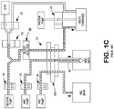
- FIGS. 1A-1C schematically illustrate a prior art apparatus 10 for aspirating and dispensing a whole blood sample WBS disposed in a container C having a rubber seal S.
- Such apparatus is part of a conventional automated instrument system that is designed to count, differentiate and otherwise analyze different types of red and white blood cells comprising the whole blood sample.
- the blood aspirating and dispensing apparatus which is more thoroughly described in the above-noted U.S. Patent No. 6,322,752 , comprises a hollow aspiration probe AP having a sharpened distal end 11 that serves to penetrate the seal S on the sample container to access the liquid sample therein.
- the aspiration probe has a proximal end 12 that is rigidly connected to a blood-sampling valve BSV.
- the aspiration probe and its rigidly connected BSV are mounted for lateral movement, i.e., movement perpendicular to the vertical direction in which they move to access sample in a container, whereby the aspirating probe can dispense its sample aliquots into chambers laterally spaced from the sample container.
- the BSV is essentially a shear valve assembly comprising three confronting pads P1, P2 and P3, each having a plurality of bore holes B, strategically located therein.
- the shear pads are movable with respect to each other to selectively cause their respective bore holes to become either aligned, whereby liquid can flow between adjacent pads, or misaligned, whereby such flow of liquid is prevented.
- FIG. 1A the shear valve is shown in a sample-loading configuration in which the blood sample can be drawn or aspirated, under the negative pressure of a vacuum pump VP, into and through three aligned bore holes in the three shear pads, and then into to a conduit 14 connected to the aligned bore hole in the top pad P3.
- a signal is transmitted to a programmable logic and control unit (LCU) that controls the operation of all system components, including the BSV, the vacuum pump VP, open/close valves VI-V6, and diluent pumps DP1-DP3.
- the LCU then operates to deactivate the vacuum pump and to adjust the relative positions of shear pads P1-P3 to the positions shown in FIG. 1B , whereby two precise aliquots (A1 and A2) of whole blood are segmented or isolated from the aspirated volume of blood for analysis.
- the smaller aliquot A1 defined by the internal volume of a bore hole formed in the intermediate pad P2, is used for determining red blood cell (RBC) count
- the larger aliquot A2 defined by the internal volume of the aspiration probe downstream of the intermediate pad P2 is used for white blood cell (WBC) count and analysis.
- the volume of aliquot A1 is defined by the thickness of pad P2 and the diameter of the bore hole therein.
- the volume of aliquot A1 for RBC analysis is selected to be between 1 and 10 microliters.
- the relatively large volume of aliquot A2 is defined by the internal volume of the aspiration probe AP, plus the volume of the bore hole in shear pad P1 through which the aspirated sample is aspirated. Typically, this volume of aliquot is between 200 and 300 microliters.
- the LCU operates apparatus 10 in a dispensing mode (shown in FIG. 1C ) in which valves V4-V6 are opened, and the diluent pumps DP1-DP3 are activated to chase the aliquots of sample to different baths for sample preparation, and to flush the non-used blood sample to a waste container.
- the RBC pump DP1 operates to dispense a predetermined volume of diluent through aliquot A1 to an RBC bath from which a diluted and mixed RBC sample is extracted and analyzed.
- the WBC pump DP2 operates to dispense a predetermined volume of diluent through aliquot A2 to a WBC bath in which different reagents (e.g. lyse, stain, etc.) are added to provide a suitable sample for WBC analysis.
- the diluent pump P3 operates to flush conduit 26 of the blood sample therein.
- FIGS. 1A-1C is disadvantageous from the standpoint that it wastes a considerable volume of the aspirated blood sample, viz., all of the blood sample positioned upstream of the BSV. As shown in FIG. 3C , all of such blood is eventually flushed to waste by the diluent pump DP3. Further, it will be noted that, until the shear valve and aspiration probe are emptied of their respective contents, the apparatus cannot be used for other purposes, e.g., the aspirating probe cannot be used in a suck-and-spit mode to further process the sample.
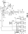
- the apparatus 20 is depicted as being embodied in a portion of a blood-analyzing system that includes a plurality of reaction chambers, RC1-RC4, in which predetermined volumes of a whole blood sample are to be mixed with various reagents to condition the samples for a particular type of analysis.
- a relatively minute and precise volume (e.g., about 15 microliters) of whole blood may be mixed with a predetermined volume of a suitable diluent to provide a precisely diluted sample that is useful in determining the red blood cell count of the sample.
- a larger, yet precise, volume of whole blood may be mixed with a suitable lytic reagent, a stabilizer and a diluent to provide a white cell sample adapted for a differential analysis of the various types and concentrations of white cells in the sample.
- a volume of blood sample may be mixed with a fluorescent dye adapted to differentially stain or otherwise tag a certain type of cell, e.g. reticulocytes.
- each reaction chamber comprises a cup portion 22 that is sealed by a lid portion 24 having a central opening 24A adapted to receive a predetermined volume of blood sample.
- the lid portions of the reaction chambers are provided with a plurality of ports through which various reagents may be introduced for reaction with the sample, and through which the prepared samples may be extracted from the chambers for analysis.
- Each reaction chamber has a port at its base through which the residual contents (after removing a portion for analysis) can be flushed to waste W.
- the liquid aspirating and dispensing apparatus 20 comprises an aspirating probe AP, a new and improved liquid-sampling valve LSV, and a bi-directional pump 30.
- the aspirating probe has a sharpened distal end adapted to puncture a seal S atop the sample container C.
- the aspiration probe is mounted, in a conventional manner, for movement in vertical and lateral directions, Z and X, respectively, so as to enable the probe tip to enter either the sample container C or any one of the reaction chambers RC1-RC4.
- Suitable apparatus i.e., an X/Z drive mechanism, for movably-mounting the aspiration probe for such movement is disclosed, for example, in the commonly assigned U.S.
- Pump 30 is preferably a conventional syringe having a movable actuator that, in moving in a first direction aspirates liquid through the aspiration probe, and in moving in an opposite direction, dispenses liquid from the probe tip.
- the aspiration probe of apparatus 20 is used to both aspirate and dispense sample material.
- a key element of apparatus 20 is the liquid-sampling valve LSV which is rigidly mounted at a suitable location within the instrument frame. Unlike the BSV's of the prior art, the liquid-sampling valve of the apparatus enables the aspiration probe to continue operating in an aspirating/dispensing mode, in which liquid can pass in either direction through the valve, after the valve has operated to position its aliquoting chambers so as to be emptied by a reagent or diluent that is caused to pass through such chambers and thereby chase the stored liquid to a reaction chamber or the like.
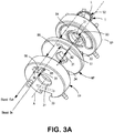
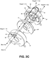
- the various components of liquid-sampling valve and its operation will be best understood with reference to the exploded perspective views of FIGS. 3A-3D .
- FIGS. 3A and 3B are front and rear views, respectively, illustrating the relative positions of the valve components while the aliquoting chambers of the valve are being filled or "loaded” with sample liquid.
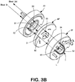
- FIGS. 3C and 3D are front and rear views, respectively, illustrating the same valve components while sample aliquots are being dispensed from the valve.
- the liquid-sampling valve is a shear valve assembly comprising three confronting, disk-shaped, valve pads, i.e., a front pad FP, a middle pad MP and a rear pad RP. In use, the three pads are contiguously arranged on a shaft (not shown) that passes through a central opening 31 in each pad.
- An elongated key member engages identical slots 33 in the periphery of the front and rear pads and acts to prevent these pads from rotating on their supporting shaft.
- the same key member engages a larger slot 34, best shown in FIGS. 3B-3C , formed in the periphery of the middle pad; because the key is narrower than slot 34, the middle pad is enabled to rotate through an angle of about 15 or 20 degrees, the extent of such movement being determined by the width of slot 34.
- each of the pads is made of a non-reactive ceramic material, and the planar, confronting surfaces of the pads are polished to prevent leakage of liquid from ports and passageways within the valve assembly when the pads are contiguously arranged.
- the sampling valve illustrated in the drawings is designed to provide two precise aliquots, S1 and S2, of a blood sample (or other liquid) for analysis or processing.
- Aliquot S1 is significantly smaller than S2 and its volume is defined by the volume of a bore hole B2 formed directly through the middle pad MP; thus, bore hole B2 is the aliquoting chamber for S1, and its volume is determined, of course, by the pad thickness and the bore hole diameter.
- Aliquot S2 is defined, in part, by the internal volume of an arcuate external tube T which is in the form of a loop L extending from and returning to two spaced bore holes B3 and B4 formed in the rear pad RP.
- the total volume of aliquot S2 is the sum of the internal volume of external tube T and the respective volumes of bore hole B4 and B3.
- bore holes B3 and B4 appear relatively large in diameter owing to a countersunk region surrounding each hole to facilitate the mounting of the looping tube on the rear pad.
- a port 35 extending forwardly of the exterior surface of front pad FP is connected to the aspiration probe AP by a flexible conduit, not shown. Port 35 is aligned with a bore hole B1 formed in the front pad.
- a surface groove G1 formed in the forward-facing surface of the middle pad MP is arcuate in shape and its center of curvature coincides with the central axis A of the support shaft.
- Groove G1 faces a planar surface on the rear side of the front pad FP and thereby defines an arcuate passageway through which the sample passes.
- Confronting groove G1 is a radially-extending groove G2 in the rearward-facing surface of the front pad FP. And confronting a portion of the groove G2 is the bore hole B2 defining sample aliquot S1 in the middle pad MP.
- Bore hole B2 is aligned with the bore hole B3 (formed in rear pad RP), which in turn is always in fluid communication with tube T and bore hole B4.
- bore hole B4 is aligned with bore hole B5 in middle pad MP and with bore hole B6 in front pad FP.
- An outlet port 36 connected to the aspiration pump 30, is rigidly connected with bore hole B6.
- an aspirated sample will enter port 35 through the aspiration probe attached thereto, fill the aliquoting chambers S1 and S2, and exit through the outlet port 36 and through an interconnected conduit leading to the aspiration pump.
- the middle pad MP of the shear valve assembly is rotated to the segmenting/dispensing position shown in FIGS. 3C and 3D .
- different groove/bore hole combinations will enable a first reagent, "Reagent 1,” to chase sample aliquot S1 from bore hole B2 in the middle pad MP, and to enable a second reagent.
- Reagent 2 to chase sample aliquot S2 from the external tube T and from bore holes B3 and B4.
- pump 30 can continue to aspirate and dispense sample liquid from the liquid container C through the aspiration probe and through the same ports 35 and 36 through which the valve was "loaded” with liquid sample. How this is achieved is described below.
- the liquid-sampling valve is shown in its segmenting/dispensing configuration in which the middle pad MP has rotated about 15 degrees counter-clockwise (as viewed in FIG. 3C ) relative to the front and rear pads, which have remained stationary.
- a liquid sample entering the entrance port 35 will again encounter groove G1, but at the opposite end of the groove from that in which the aspirated liquid encountered the groove during the loading mode.
- the opposite end of groove 1 is now positioned opposite bore hole B6 in the front pad.
- the aspirated sample entering entrance port 35 will be immediately directed through bore hole B6 which is connected to the outlet port 36.
- the liquid aspiration and dispense apparatus can continue to operate in the aspirating/dispense (suck and spit) mode, aspirating sample to the upstream side (i.e., the pump side) of the liquid-sampling valve, while the sampling valve has operated to position the sample aliquots S1 and S2 to be dispensed.
- the middle pad MP In rotating to its segmenting and dispensing position, the middle pad MP operates to shear aliquots S1 and S2 from the liquid path established during the loading mode, and to position such aliquots for dispensing. Dispensing of aliquot S1 is achieved by directing Reagent 1 through a first reagent entry port 40 in the front pad FP. Through a groove G3 in the front pad, the Reagent 1 path becomes aligned with bore hole B2 in the middle pad. The entering reagent chases sample aliquot S1 out of bore hole B2 through a bore hole B7 in the rear pad, and then through a first reagent exit port 42 aligned with bore hole B7.
- Dispensing of aliquot S2 is achieved by directing Reagent 2 through a second reagent entry port 50 extending from the rear pad RP. Port 50 is connected to a bore hole B8 in the rear pad. Upon passing through bore hole B8, Reagent 2 encounters arcuate groove G4 in the rear surface of the middle pad. Groove G4 serves to shift the fluid path of the reagent be aligned with bore hole B4 (shown in FIG. 3A ). Thus, as Reagent 2 enters bore hole B4, it will expel the isolated sample aliquot S2 out through bore hole B3 formed in rear pad RP.
- the path of the expelled sample Upon encountering a groove G5 in the rear surface of the middle pad MP, the path of the expelled sample will align with a bore hole B9 formed in the rear pad RP, and the S2 aliquot will emerge from the valve assembly through the second reagent exit port 52 which is aligned with bore hole B9.
- the liquid sampling valve is shown as comprising additional ports, grooves and bore holes; but none of the additional elements have any effect on the operation of the valve, as heretofore described.
- liquid sample noted above is a whole blood sample to be analyzed in a conventional manner.
- all conduits are primed with cleaning reagent or diluent.
- a small air gap is created at the tip of the aspiration probe by momentarily activating the syringe pump 30 before the probe tip enters the sample.
- the aspirating probe is driven downward to puncture the container seal S (if the container is sealed) and to enter the whole blood sample.
- the syringe pump 30 is operated in a negative-pressure (sucking) mode to draw the sample through a flexible conduit 55 leading to the liquid-sample valve.
- the system will begin to monitor the output of a first photoelectric blood detector BD1 which, after detecting the air gap, will monitor the integrity of the blood sample to assure the absence of any bubbles that would compromise the precision of the sample volumes to be dispensed.
- a second blood detector BD2 After the aspirated sample has advanced through the liquid-sampling valve and has exited through the outlet port 36 and into a second flexible conduit 56, a second blood detector BD2 will detect the leading air gap and signal the system's logic and control unit (LCU) that the aspirated sample has been loaded into the LSV. After confirming the detection of a blood sample by the second blood detector BD2, the LCU will energize a mechanical driver 58 adapted to cause the middle pad MP of the LSV to rotate to its sample segment/dispense position (shown in FIGS. 3C and 3D ), thereby isolating sample aliquots S1 and S2 and positioning them for dispensing.
- LCU system's logic and control unit
- a reagent pumping system (not shown) will then be activated to advance Reagents 1 and 2 into the sampling valve for the purpose of chasing the isolated sample aliquots S1 and S2 to the respective entry ports 60 of reaction chambers RC1 and RC2.
- Flexible conduits 61 and 62 directly connect the sample valve's outlet ports 42 and 52 to the entry ports of the reaction chambers.
- apparatus 20 is free to operate in a suck-and-spit mode in which it is capable of dispensing virtually all of the excess sample previously aspirated to load the LSV, and of subsequently aspirating and dispensing more sample from the container or any of the reaction chambers.
- the aspiration probe is ready to be moved into and out of the various reaction chambers of the system, for example, to effect movement of different liquids within the system for subsequent processing.
- the syringe pump will first push the liquid sample to completely fill the aspiration probe.
- the syringe pump will then dispense a predetermined relatively large volume (e.g., at least 10 microliters) of liquid by controlling the movement of the syringe actuator.
- the sample mixing and/or delivery of additional reagent material serves to wash the sample drop from the probe tip.
- the reagent agitation in the reaction chamber will also assure a relatively high accuracy of the liquid dispensing, which is preferably controlled by a step motor-driven syringe pump.
- the system will wash the outside of the probe using, for example, probe washer 70 having a housing 72 in which the probe is slidably mounted.
- a diluent or cleansing fluid is provided under pressure to the probe-washing housing, and the resulting effluent is flushed to waste W.
- the syringe pump will push out a small amount of sample to rid the probe of any contaminating reagent from the previous reaction chamber. This sample over-dispense to waste will also ensure that the liquid sample is primed to the probe tip.
- the aspiration probe may be moved to a position in which it enters the reaction chamber RC4, which contains a fluorescent stain reagent.
- the probe may be used again, after a thorough cleaning operation, to aspirate a portion of the stained sample from reaction chamber RC4 and to transport stained sample to reaction chamber RC3 where it is precisely dispensed using, for example, a stepper motor-controlled syringe pump.
- a syringe pump is particularly preferred in implementing the invention, it will be apparent that any precision pumping system can be used to advance a liquid through the liquid sampling valve in opposite directions.
- the method of the invention is "hybrid” in nature in that it combines both of the aforementioned BSV and suck-and-spit approaches to liquid dispensing.
- the method of the invention has the advantageous technical effect of reducing (e.g., by as much as a factor of three) the number of liquid-sampling valves (e.g., BSV's) used in high-throughput hematology instruments since some of the liquid- sampling valves can be eliminated in favor of the far less expensive suck-and-spit approach to dispensing liquids.
Landscapes
- Physics & Mathematics (AREA)
- Health & Medical Sciences (AREA)
- Life Sciences & Earth Sciences (AREA)
- Chemical & Material Sciences (AREA)
- Analytical Chemistry (AREA)
- Biochemistry (AREA)
- General Health & Medical Sciences (AREA)
- General Physics & Mathematics (AREA)
- Immunology (AREA)
- Pathology (AREA)
- Automatic Analysis And Handling Materials Therefor (AREA)
- Sampling And Sample Adjustment (AREA)
Claims (6)
- Procédé d'aspiration et de distribution d'un échantillon liquide dans un instrument d'analyse automatisé, ledit procédé comprenant l'utilisation d'un appareil comprenant :(a) une sonde d'aspiration (AP), connectée de manière opérationnelle à une pompe (30), et adaptée pour pénétrer dans un récipient d'échantillon (C) pour aspirer un échantillon liquide dans ledit récipient (C) ;(b) un système de transport pour faire progresser sélectivement la sonde d'aspiration (AP) dans des plans réciproquement perpendiculaires de sorte que ladite sonde d'aspiration (AP) peut aspirer ou distribuer du liquide depuis, ou à, différents récipients (C) espacés ; et(c) une vanne d'échantillonnage de liquide (LSV), connectée de manière opérationnelle entre ladite sonde d'aspiration (AP) et ladite pompe (30), et comprenant une structure définissant au moins une chambre d'aliquotage (S1, S2) pour stocker temporairement un volume précis d'échantillon liquide à distribuer ;le procédé comprenant l'utilisation de la pompe (30) sélectivement soit (i) pour extraire un échantillon liquide par l'intermédiaire de ladite sonde d'aspiration (AP) et par l'intermédiaire de la vanne d'échantillonnage de liquide (LSV) pour remplir ladite chambre d'aliquotage (S1 ; S2), soit (ii) pour distribuer un échantillon liquide déjà aspiré par l'intermédiaire de ladite vanne d'échantillonnage de liquide (LSV) et par l'intermédiaire de ladite sonde d'aspiration (AP) ;
le procédé comprenant outre l'utilisation de la vanne d'échantillonnage de liquide (LSV) sélectivement soit (i) dans une configuration de chargement dans laquelle l'échantillon liquide aspiré par la sonde d'aspiration (AP) sous l'effet de la pompe (30) passera à travers la vanne d'échantillonnage de liquide (LSV) tout en remplissant simultanément ladite chambre d'aliquotage (S1 ; S2) de celui-ci, soit (ii) dans une configuration de segmentation/distribution dans laquelle l'échantillon liquide dans ladite chambre d'aliquotage (S1 ; S2) est positionné pour être distribué depuis ladite vanne d'échantillonnage de liquide (LSV) à une chambre de réaction (RC1, RC2) par une force externe à la vanne d'échantillonnage de liquide, pendant que ladite pompe (30) fonctionne dans un mode d'aspiration-distribution aspirant un échantillon liquide d'un récipient d'échantillon (C) et distribuant un échantillon liquide déjà aspiré à une chambre de réaction (RC3, RC4) par l'intermédiaire de ladite sonde d'aspiration (AP) et par l'intermédiaire de ladite vanne d'échantillonnage de liquide (LSV). - Procédé selon la revendication 1 dans lequel ladite pompe (30) est une pompe-seringue commandée par un moteur pas à pas (30).
- Procédé selon la revendication 1 dans lequel ladite vanne d'échantillonnage de liquide (LSV) est un ensemble vanne de cisaillement qui comprend une pluralité de brides de vanne opposés et contigus (FP, MP, RP), chacune desdites brides de vanne (FP, MP, RP) ayant une structure qui coopère avec la structure d'une bride adjacente pour définir différents trajets d'écoulement de liquide dans ledit ensemble vanne de cisaillement, au moins une desdites brides étant mobile par rapport à l'autre desdites brides pour définir soit (a) une configuration de chargement dans laquelle une première chambre d'aliquotage (S1) est positionnée dans un premier trajet d'écoulement et se remplit d'un liquide aspiré par l'intermédiaire de ladite sonde d'aspiration (AP) et par l'intermédiaire dudit ensemble vanne par ladite pompe (30), soit (b) une configuration de segmentation/distribution dans laquelle (i) le liquide dans ladite première chambre d'aliquotage (S1) est positionné pour être soumis à une force externe pour dispenser ce liquide depuis ladite première chambre d'aliquotage (S1) selon un deuxième trajet d'écoulement, et (ii) le liquide peut soit être aspiré, soit distribué par l'intermédiaire dudit ensemble vanne selon un troisième trajet d'écoulement par ladite pompe (30).
- Procédé selon la revendication 3 dans lequel ladite première chambre d'aliquotage (S1) est définie par un trou traversant (B2) passant à travers une desdites brides de vanne (FP, MP, RP).
- Procédé selon la revendication 4 dans lequel ledit ensemble vanne de cisaillement comprend trois brides de vanne (FP ; MP ; RP), et dans lequel ledit trou traversant (B2) est formé dans une bride intermédiaire (MP) desdites trois brides de vanne (FP ; MP ; RP).
- Procédé selon la revendication 3 dans lequel une seconde chambre d'aliquotage (S2) est positionnée dans ledit premier trajet d'écoulement et se remplit de liquide aspiré par l'intermédiaire de ladite vanne d'échantillonnage de liquide (LSV) lorsque ladite vanne d'aspiration de liquide (LSV) se trouve dans sa configuration de chargement, et dans lequel le liquide dans ladite seconde chambre d'aliquotage (S2) est positionné pour subir une force externe pour distribuer ce liquide depuis ladite seconde chambre d'aliquotage selon un quatrième trajet d'écoulement lorsque ladite vanne d'échantillonnage de liquide (LSV) se trouve dans sa configuration de segmentation/distribution.
Applications Claiming Priority (2)
| Application Number | Priority Date | Filing Date | Title |
|---|---|---|---|
| US11/553,107 US7661326B2 (en) | 2006-10-26 | 2006-10-26 | Apparatus for aspirating and dispensing liquids in an automated analyzer |
| PCT/US2007/077834 WO2008051659A1 (fr) | 2006-10-26 | 2007-09-07 | Appareil pour aspirer et distribuer des liquides dans un analyseur automatise |
Publications (3)
| Publication Number | Publication Date |
|---|---|
| EP2076766A1 EP2076766A1 (fr) | 2009-07-08 |
| EP2076766A4 EP2076766A4 (fr) | 2017-08-30 |
| EP2076766B1 true EP2076766B1 (fr) | 2021-05-26 |
Family
ID=39324911
Family Applications (1)
| Application Number | Title | Priority Date | Filing Date |
|---|---|---|---|
| EP07814726.1A Active EP2076766B1 (fr) | 2006-10-26 | 2007-09-07 | Procédé pour aspirer et distribuer des liquides dans un analyseur automatise |
Country Status (5)
| Country | Link |
|---|---|
| US (1) | US7661326B2 (fr) |
| EP (1) | EP2076766B1 (fr) |
| JP (2) | JP5213269B2 (fr) |
| CN (2) | CN101529243B (fr) |
| WO (1) | WO2008051659A1 (fr) |
Families Citing this family (20)
| Publication number | Priority date | Publication date | Assignee | Title |
|---|---|---|---|---|
| US8454893B2 (en) * | 2007-03-15 | 2013-06-04 | Medi-Physics, Inc. | Fluid sampling system with an in-line probe |
| JP5162177B2 (ja) * | 2007-07-31 | 2013-03-13 | シスメックス株式会社 | 粒子分析装置及び粒子分析方法 |
| RU2636614C2 (ru) * | 2009-05-19 | 2017-11-24 | Вивия Байотек С.Л. | Способы персонализированного медицинского тестирования ex vivo на гематологические новообразования |
| US20100329927A1 (en) | 2009-06-26 | 2010-12-30 | Perez Carlos A | Pipelining Assembly For A Blood Analyzing Instrument |
| CN103090050B (zh) * | 2011-10-31 | 2015-06-17 | 深圳迈瑞生物医疗电子股份有限公司 | 分液阀及具有该分液阀的医疗设备 |
| JP2013255447A (ja) * | 2012-06-12 | 2013-12-26 | Nippon Koden Corp | 細胞単離装置 |
| CN104487819B (zh) * | 2012-06-22 | 2017-10-27 | 生物辐射实验室股份有限公司 | 两站式样本及洗涤系统 |
| BR112015000018B1 (pt) | 2012-07-05 | 2021-11-09 | Beckman Coulter, Inc | Sistema e método automatizado para determinar uma condição de células brancas do sangue em uma amostra biológica |
| WO2014151234A1 (fr) * | 2013-03-15 | 2014-09-25 | Bell Michael L | Dispositif et procédé d'analyse |
| CN104297108B (zh) * | 2013-07-16 | 2017-09-05 | 成都深迈瑞医疗电子技术研究院有限公司 | 粒子分析仪及其液路系统 |
| US11169060B2 (en) * | 2015-11-18 | 2021-11-09 | Beckman Coulter, Inc. | Filtering device for analyzing instrument |
| ES2770711T3 (es) | 2016-05-11 | 2020-07-02 | Diatron Mi Zrt | Dispositivo para tomar muestras de líquidos con alta precisión en un analizador de muestras automatizado |
| JP6885965B2 (ja) * | 2016-10-26 | 2021-06-16 | 株式会社島津製作所 | フロースルーバイアル及びオートサンプラ |
| DE102016121512A1 (de) * | 2016-11-10 | 2018-05-17 | Dionex Softron Gmbh | System, Verfahren und Verwendung der Flüssigkeitschromatografie |
| DE102016121516B4 (de) * | 2016-11-10 | 2019-03-28 | Dionex Softron Gmbh | Verfahren und Vorrichtung zur Probenbeschickung |
| DE102016121519B4 (de) * | 2016-11-10 | 2019-07-11 | Dionex Softron Gmbh | System und Verfahren zum Verbinden von Komponenten, insbesondere in der HPLC |
| US20210308665A1 (en) * | 2018-07-24 | 2021-10-07 | Lic Automation Limited | A System and Apparatus for Fluid Sample Delivery |
| WO2021019267A1 (fr) | 2019-07-26 | 2021-02-04 | Bit Group France | Procédé de distribution différentielle |
| WO2021097610A1 (fr) * | 2019-11-18 | 2021-05-27 | 深圳迈瑞生物医疗电子股份有限公司 | Analyseur d'échantillon et procédé d'analyse d'échantillon |
| CN112798345A (zh) * | 2020-12-29 | 2021-05-14 | 深圳市科曼医疗设备有限公司 | 预稀释模式的样本采集和分配系统、方法及血液细胞分析仪 |
Family Cites Families (15)
| Publication number | Priority date | Publication date | Assignee | Title |
|---|---|---|---|---|
| JPS5813338Y2 (ja) * | 1977-03-31 | 1983-03-15 | 株式会社島津製作所 | 液体試料分注装置 |
| US4896546A (en) | 1987-10-26 | 1990-01-30 | Coulter Electronics, Inc. | Liquid metering and transfer valve assembly |
| JP2519488B2 (ja) * | 1987-11-25 | 1996-07-31 | 東亜医用電子株式会社 | 試料定量弁 |
| US4957008A (en) | 1988-12-28 | 1990-09-18 | Coulter Electronics, Inc. | Fluid sampling and transfer valve assembly |
| US5158751A (en) * | 1990-12-13 | 1992-10-27 | Coulter Corporation | Liquid metering and transfer valve assembly |
| JP3130608B2 (ja) * | 1991-11-20 | 2001-01-31 | シスメックス株式会社 | サンプリングバルブ |
| WO1993010432A1 (fr) | 1991-11-22 | 1993-05-27 | Coulter Corporation | Dispositif a valves pour mesurer, melanger et transferer un fluide, et systeme analytique utilisant ce dispositif |
| US5691486A (en) * | 1996-07-30 | 1997-11-25 | Bayer Corporation | Apparatus and methods for selecting a variable number of test sample aliquots to mix with respective reagents |
| JP3880181B2 (ja) * | 1997-12-22 | 2007-02-14 | シスメックス株式会社 | 血液分析装置 |
| US6322752B1 (en) | 1999-09-08 | 2001-11-27 | Coulter International Corp. | Method and apparatus for aspirating and dispensing liquids |
| US7255833B2 (en) * | 2000-07-25 | 2007-08-14 | Cepheid | Apparatus and reaction vessel for controlling the temperature of a sample |
| JP3815322B2 (ja) * | 2001-12-27 | 2006-08-30 | 株式会社島津製作所 | 試料導入装置 |
| US7288228B2 (en) * | 2002-02-12 | 2007-10-30 | Gilson, Inc. | Sample injection system |
| EP1624301B1 (fr) * | 2003-05-15 | 2013-10-30 | Shiseido Company, Ltd. | Procede d'injection d'echantillon pour chromatographie en phase liquide |
| US7481978B2 (en) | 2005-03-23 | 2009-01-27 | Beckman Coulter, Inc. | Apparatus for aspirating liquids from sealed containers |
-
2006
- 2006-10-26 US US11/553,107 patent/US7661326B2/en active Active
-
2007
- 2007-09-07 JP JP2009534734A patent/JP5213269B2/ja active Active
- 2007-09-07 CN CN2007800396149A patent/CN101529243B/zh active Active
- 2007-09-07 EP EP07814726.1A patent/EP2076766B1/fr active Active
- 2007-09-07 CN CN201210308797.2A patent/CN102998474B/zh active Active
- 2007-09-07 WO PCT/US2007/077834 patent/WO2008051659A1/fr active Application Filing
-
2012
- 2012-07-02 JP JP2012148685A patent/JP5213286B2/ja active Active
Non-Patent Citations (1)
| Title |
|---|
| None * |
Also Published As
| Publication number | Publication date |
|---|---|
| CN102998474B (zh) | 2014-12-17 |
| WO2008051659A1 (fr) | 2008-05-02 |
| US20080098828A1 (en) | 2008-05-01 |
| JP5213269B2 (ja) | 2013-06-19 |
| WO2008051659A8 (fr) | 2009-04-16 |
| JP2010508514A (ja) | 2010-03-18 |
| CN102998474A (zh) | 2013-03-27 |
| EP2076766A1 (fr) | 2009-07-08 |
| CN101529243B (zh) | 2013-01-23 |
| JP2012185188A (ja) | 2012-09-27 |
| CN101529243A (zh) | 2009-09-09 |
| JP5213286B2 (ja) | 2013-06-19 |
| EP2076766A4 (fr) | 2017-08-30 |
| US7661326B2 (en) | 2010-02-16 |
Similar Documents
| Publication | Publication Date | Title |
|---|---|---|
| EP2076766B1 (fr) | Procédé pour aspirer et distribuer des liquides dans un analyseur automatise | |
| US6322752B1 (en) | Method and apparatus for aspirating and dispensing liquids | |
| US5380491A (en) | Apparatus for pumping and directing fluids for hematology testing | |
| EP1891413B1 (fr) | Cartouche echantillon double et procede de caracterisation d`une particule dans un liquide | |
| WO2018009920A1 (fr) | Analyse automatisée de cellules microscopiques | |
| US11590496B2 (en) | Automated microscopic cell analysis | |
| US3759667A (en) | Apparatus for aspirating precise volumes of fluid sample | |
| US5728351A (en) | Apparatus for making a plurality of reagent mixtures and analyzing particle distributions of the reagent mixtures | |
| JPH08178824A (ja) | 粒子測定装置 | |
| US20030012694A1 (en) | System for the analysis of biological liquids | |
| US6812032B1 (en) | Apparatus and method for making a plurality of reagent mixtures and analyzing particle distributions of the reagent mixtures | |
| US10768192B2 (en) | Device and method to sample liquids with high-precision in an automated sample analyzer | |
| EP1189059A1 (fr) | Détecteur de cellules sanguines, analyseur de sang et méthode utilisant le détecteur | |
| JPH04369461A (ja) | 粒子計測装置 | |
| JPH05119036A (ja) | 粒子計測装置 | |
| EP0789843B1 (fr) | Appareil permettant de pomper et de diriger des fluides en vue d'effectuer un test d'hematologie | |
| JPH06289034A (ja) | 試料処理装置 |
Legal Events
| Date | Code | Title | Description |
|---|---|---|---|
| PUAI | Public reference made under article 153(3) epc to a published international application that has entered the european phase |
Free format text: ORIGINAL CODE: 0009012 |
|
| 17P | Request for examination filed |
Effective date: 20090323 |
|
| AK | Designated contracting states |
Kind code of ref document: A1 Designated state(s): AT BE BG CH CY CZ DE DK EE ES FI FR GB GR HU IE IS IT LI LT LU LV MC MT NL PL PT RO SE SI SK TR |
|
| RAP1 | Party data changed (applicant data changed or rights of an application transferred) |
Owner name: BECKMAN COULTER, INC. |
|
| RAP1 | Party data changed (applicant data changed or rights of an application transferred) |
Owner name: BECKMAN COULTER, INC. |
|
| DAX | Request for extension of the european patent (deleted) | ||
| RA4 | Supplementary search report drawn up and despatched (corrected) |
Effective date: 20170727 |
|
| RIC1 | Information provided on ipc code assigned before grant |
Ipc: G01N 35/10 20060101ALI20170721BHEP Ipc: G01N 30/20 20060101AFI20170721BHEP |
|
| STAA | Information on the status of an ep patent application or granted ep patent |
Free format text: STATUS: EXAMINATION IS IN PROGRESS |
|
| 17Q | First examination report despatched |
Effective date: 20190708 |
|
| GRAP | Despatch of communication of intention to grant a patent |
Free format text: ORIGINAL CODE: EPIDOSNIGR1 |
|
| STAA | Information on the status of an ep patent application or granted ep patent |
Free format text: STATUS: GRANT OF PATENT IS INTENDED |
|
| INTG | Intention to grant announced |
Effective date: 20210122 |
|
| GRAS | Grant fee paid |
Free format text: ORIGINAL CODE: EPIDOSNIGR3 |
|
| GRAA | (expected) grant |
Free format text: ORIGINAL CODE: 0009210 |
|
| STAA | Information on the status of an ep patent application or granted ep patent |
Free format text: STATUS: THE PATENT HAS BEEN GRANTED |
|
| AK | Designated contracting states |
Kind code of ref document: B1 Designated state(s): AT BE BG CH CY CZ DE DK EE ES FI FR GB GR HU IE IS IT LI LT LU LV MC MT NL PL PT RO SE SI SK TR |
|
| REG | Reference to a national code |
Ref country code: GB Ref legal event code: FG4D |
|
| REG | Reference to a national code |
Ref country code: CH Ref legal event code: EP |
|
| REG | Reference to a national code |
Ref country code: DE Ref legal event code: R096 Ref document number: 602007061148 Country of ref document: DE |
|
| REG | Reference to a national code |
Ref country code: AT Ref legal event code: REF Ref document number: 1396733 Country of ref document: AT Kind code of ref document: T Effective date: 20210615 |
|
| REG | Reference to a national code |
Ref country code: IE Ref legal event code: FG4D |
|
| REG | Reference to a national code |
Ref country code: LT Ref legal event code: MG9D |
|
| REG | Reference to a national code |
Ref country code: AT Ref legal event code: MK05 Ref document number: 1396733 Country of ref document: AT Kind code of ref document: T Effective date: 20210526 |
|
| PG25 | Lapsed in a contracting state [announced via postgrant information from national office to epo] |
Ref country code: LT Free format text: LAPSE BECAUSE OF FAILURE TO SUBMIT A TRANSLATION OF THE DESCRIPTION OR TO PAY THE FEE WITHIN THE PRESCRIBED TIME-LIMIT Effective date: 20210526 Ref country code: FI Free format text: LAPSE BECAUSE OF FAILURE TO SUBMIT A TRANSLATION OF THE DESCRIPTION OR TO PAY THE FEE WITHIN THE PRESCRIBED TIME-LIMIT Effective date: 20210526 Ref country code: AT Free format text: LAPSE BECAUSE OF FAILURE TO SUBMIT A TRANSLATION OF THE DESCRIPTION OR TO PAY THE FEE WITHIN THE PRESCRIBED TIME-LIMIT Effective date: 20210526 Ref country code: BG Free format text: LAPSE BECAUSE OF FAILURE TO SUBMIT A TRANSLATION OF THE DESCRIPTION OR TO PAY THE FEE WITHIN THE PRESCRIBED TIME-LIMIT Effective date: 20210826 |
|
| REG | Reference to a national code |
Ref country code: NL Ref legal event code: MP Effective date: 20210526 |
|
| PG25 | Lapsed in a contracting state [announced via postgrant information from national office to epo] |
Ref country code: PT Free format text: LAPSE BECAUSE OF FAILURE TO SUBMIT A TRANSLATION OF THE DESCRIPTION OR TO PAY THE FEE WITHIN THE PRESCRIBED TIME-LIMIT Effective date: 20210927 Ref country code: PL Free format text: LAPSE BECAUSE OF FAILURE TO SUBMIT A TRANSLATION OF THE DESCRIPTION OR TO PAY THE FEE WITHIN THE PRESCRIBED TIME-LIMIT Effective date: 20210526 Ref country code: LV Free format text: LAPSE BECAUSE OF FAILURE TO SUBMIT A TRANSLATION OF THE DESCRIPTION OR TO PAY THE FEE WITHIN THE PRESCRIBED TIME-LIMIT Effective date: 20210526 Ref country code: GR Free format text: LAPSE BECAUSE OF FAILURE TO SUBMIT A TRANSLATION OF THE DESCRIPTION OR TO PAY THE FEE WITHIN THE PRESCRIBED TIME-LIMIT Effective date: 20210827 Ref country code: IS Free format text: LAPSE BECAUSE OF FAILURE TO SUBMIT A TRANSLATION OF THE DESCRIPTION OR TO PAY THE FEE WITHIN THE PRESCRIBED TIME-LIMIT Effective date: 20210926 Ref country code: SE Free format text: LAPSE BECAUSE OF FAILURE TO SUBMIT A TRANSLATION OF THE DESCRIPTION OR TO PAY THE FEE WITHIN THE PRESCRIBED TIME-LIMIT Effective date: 20210526 |
|
| PG25 | Lapsed in a contracting state [announced via postgrant information from national office to epo] |
Ref country code: NL Free format text: LAPSE BECAUSE OF FAILURE TO SUBMIT A TRANSLATION OF THE DESCRIPTION OR TO PAY THE FEE WITHIN THE PRESCRIBED TIME-LIMIT Effective date: 20210526 |
|
| PG25 | Lapsed in a contracting state [announced via postgrant information from national office to epo] |
Ref country code: SK Free format text: LAPSE BECAUSE OF FAILURE TO SUBMIT A TRANSLATION OF THE DESCRIPTION OR TO PAY THE FEE WITHIN THE PRESCRIBED TIME-LIMIT Effective date: 20210526 Ref country code: EE Free format text: LAPSE BECAUSE OF FAILURE TO SUBMIT A TRANSLATION OF THE DESCRIPTION OR TO PAY THE FEE WITHIN THE PRESCRIBED TIME-LIMIT Effective date: 20210526 Ref country code: DK Free format text: LAPSE BECAUSE OF FAILURE TO SUBMIT A TRANSLATION OF THE DESCRIPTION OR TO PAY THE FEE WITHIN THE PRESCRIBED TIME-LIMIT Effective date: 20210526 Ref country code: CZ Free format text: LAPSE BECAUSE OF FAILURE TO SUBMIT A TRANSLATION OF THE DESCRIPTION OR TO PAY THE FEE WITHIN THE PRESCRIBED TIME-LIMIT Effective date: 20210526 Ref country code: ES Free format text: LAPSE BECAUSE OF FAILURE TO SUBMIT A TRANSLATION OF THE DESCRIPTION OR TO PAY THE FEE WITHIN THE PRESCRIBED TIME-LIMIT Effective date: 20210526 Ref country code: RO Free format text: LAPSE BECAUSE OF FAILURE TO SUBMIT A TRANSLATION OF THE DESCRIPTION OR TO PAY THE FEE WITHIN THE PRESCRIBED TIME-LIMIT Effective date: 20210526 |
|
| REG | Reference to a national code |
Ref country code: DE Ref legal event code: R097 Ref document number: 602007061148 Country of ref document: DE |
|
| PLBE | No opposition filed within time limit |
Free format text: ORIGINAL CODE: 0009261 |
|
| STAA | Information on the status of an ep patent application or granted ep patent |
Free format text: STATUS: NO OPPOSITION FILED WITHIN TIME LIMIT |
|
| REG | Reference to a national code |
Ref country code: CH Ref legal event code: PL |
|
| 26N | No opposition filed |
Effective date: 20220301 |
|
| REG | Reference to a national code |
Ref country code: BE Ref legal event code: MM Effective date: 20210930 |
|
| PG25 | Lapsed in a contracting state [announced via postgrant information from national office to epo] |
Ref country code: IS Free format text: LAPSE BECAUSE OF FAILURE TO SUBMIT A TRANSLATION OF THE DESCRIPTION OR TO PAY THE FEE WITHIN THE PRESCRIBED TIME-LIMIT Effective date: 20210926 Ref country code: MC Free format text: LAPSE BECAUSE OF FAILURE TO SUBMIT A TRANSLATION OF THE DESCRIPTION OR TO PAY THE FEE WITHIN THE PRESCRIBED TIME-LIMIT Effective date: 20210526 |
|
| PG25 | Lapsed in a contracting state [announced via postgrant information from national office to epo] |
Ref country code: LU Free format text: LAPSE BECAUSE OF NON-PAYMENT OF DUE FEES Effective date: 20210907 Ref country code: IT Free format text: LAPSE BECAUSE OF FAILURE TO SUBMIT A TRANSLATION OF THE DESCRIPTION OR TO PAY THE FEE WITHIN THE PRESCRIBED TIME-LIMIT Effective date: 20210526 Ref country code: IE Free format text: LAPSE BECAUSE OF NON-PAYMENT OF DUE FEES Effective date: 20210907 Ref country code: BE Free format text: LAPSE BECAUSE OF NON-PAYMENT OF DUE FEES Effective date: 20210930 |
|
| PG25 | Lapsed in a contracting state [announced via postgrant information from national office to epo] |
Ref country code: LI Free format text: LAPSE BECAUSE OF NON-PAYMENT OF DUE FEES Effective date: 20210930 Ref country code: CH Free format text: LAPSE BECAUSE OF NON-PAYMENT OF DUE FEES Effective date: 20210930 |
|
| PG25 | Lapsed in a contracting state [announced via postgrant information from national office to epo] |
Ref country code: HU Free format text: LAPSE BECAUSE OF FAILURE TO SUBMIT A TRANSLATION OF THE DESCRIPTION OR TO PAY THE FEE WITHIN THE PRESCRIBED TIME-LIMIT; INVALID AB INITIO Effective date: 20070907 Ref country code: CY Free format text: LAPSE BECAUSE OF FAILURE TO SUBMIT A TRANSLATION OF THE DESCRIPTION OR TO PAY THE FEE WITHIN THE PRESCRIBED TIME-LIMIT Effective date: 20210526 |
|
| P01 | Opt-out of the competence of the unified patent court (upc) registered |
Effective date: 20230529 |
|
| PGFP | Annual fee paid to national office [announced via postgrant information from national office to epo] |
Ref country code: GB Payment date: 20230720 Year of fee payment: 17 |
|
| PGFP | Annual fee paid to national office [announced via postgrant information from national office to epo] |
Ref country code: FR Payment date: 20230703 Year of fee payment: 17 Ref country code: DE Payment date: 20230712 Year of fee payment: 17 |