EP2076095A2 - Feu de signalisation tricolore à DEL - Google Patents
Feu de signalisation tricolore à DEL Download PDFInfo
- Publication number
- EP2076095A2 EP2076095A2 EP08254135A EP08254135A EP2076095A2 EP 2076095 A2 EP2076095 A2 EP 2076095A2 EP 08254135 A EP08254135 A EP 08254135A EP 08254135 A EP08254135 A EP 08254135A EP 2076095 A2 EP2076095 A2 EP 2076095A2
- Authority
- EP
- European Patent Office
- Prior art keywords
- power
- circuit
- led array
- input
- led
- Prior art date
- Legal status (The legal status is an assumption and is not a legal conclusion. Google has not performed a legal analysis and makes no representation as to the accuracy of the status listed.)
- Granted
Links
- 238000001514 detection method Methods 0.000 claims abstract description 25
- 238000005286 illumination Methods 0.000 claims abstract description 10
- 230000003287 optical effect Effects 0.000 claims abstract description 8
- 238000012544 monitoring process Methods 0.000 claims description 10
- 238000012360 testing method Methods 0.000 claims description 10
- WYTGDNHDOZPMIW-RCBQFDQVSA-N alstonine Natural products C1=CC2=C3C=CC=CC3=NC2=C2N1C[C@H]1[C@H](C)OC=C(C(=O)OC)[C@H]1C2 WYTGDNHDOZPMIW-RCBQFDQVSA-N 0.000 claims description 9
- 238000009413 insulation Methods 0.000 claims description 5
- 239000003990 capacitor Substances 0.000 claims description 4
- 238000000034 method Methods 0.000 claims description 3
- 238000009420 retrofitting Methods 0.000 claims description 2
- 238000013461 design Methods 0.000 description 8
- 239000003086 colorant Substances 0.000 description 7
- 238000013459 approach Methods 0.000 description 4
- 230000004075 alteration Effects 0.000 description 2
- 238000003491 array Methods 0.000 description 2
- 230000008901 benefit Effects 0.000 description 2
- 238000007664 blowing Methods 0.000 description 2
- 238000010586 diagram Methods 0.000 description 2
- 238000012986 modification Methods 0.000 description 2
- 230000004048 modification Effects 0.000 description 2
- XLYOFNOQVPJJNP-UHFFFAOYSA-N water Substances O XLYOFNOQVPJJNP-UHFFFAOYSA-N 0.000 description 2
- 230000009471 action Effects 0.000 description 1
- 230000015556 catabolic process Effects 0.000 description 1
- 230000009849 deactivation Effects 0.000 description 1
- 230000002950 deficient Effects 0.000 description 1
- 238000006731 degradation reaction Methods 0.000 description 1
- 230000002939 deleterious effect Effects 0.000 description 1
- 230000000694 effects Effects 0.000 description 1
- 230000004907 flux Effects 0.000 description 1
- 230000036039 immunity Effects 0.000 description 1
- 230000000977 initiatory effect Effects 0.000 description 1
- 239000011159 matrix material Substances 0.000 description 1
- 239000013618 particulate matter Substances 0.000 description 1
- 150000003071 polychlorinated biphenyls Chemical class 0.000 description 1
- 230000009467 reduction Effects 0.000 description 1
- 230000001105 regulatory effect Effects 0.000 description 1
- 230000004044 response Effects 0.000 description 1
- 230000011664 signaling Effects 0.000 description 1
- WFKWXMTUELFFGS-UHFFFAOYSA-N tungsten Chemical compound [W] WFKWXMTUELFFGS-UHFFFAOYSA-N 0.000 description 1
- 229910052721 tungsten Inorganic materials 0.000 description 1
- 239000010937 tungsten Substances 0.000 description 1
Images


Classifications
-
- B—PERFORMING OPERATIONS; TRANSPORTING
- B61—RAILWAYS
- B61L—GUIDING RAILWAY TRAFFIC; ENSURING THE SAFETY OF RAILWAY TRAFFIC
- B61L5/00—Local operating mechanisms for points or track-mounted scotch-blocks; Visible or audible signals; Local operating mechanisms for visible or audible signals
- B61L5/12—Visible signals
- B61L5/18—Light signals; Mechanisms associated therewith, e.g. blinders
- B61L5/1809—Daylight signals
- B61L5/1827—Daylight signals using light sources of different colours and a common optical system
-
- B—PERFORMING OPERATIONS; TRANSPORTING
- B61—RAILWAYS
- B61L—GUIDING RAILWAY TRAFFIC; ENSURING THE SAFETY OF RAILWAY TRAFFIC
- B61L5/00—Local operating mechanisms for points or track-mounted scotch-blocks; Visible or audible signals; Local operating mechanisms for visible or audible signals
- B61L5/12—Visible signals
- B61L5/18—Light signals; Mechanisms associated therewith, e.g. blinders
- B61L5/1809—Daylight signals
- B61L5/1881—Wiring diagrams for power supply, control or testing
-
- H—ELECTRICITY
- H05—ELECTRIC TECHNIQUES NOT OTHERWISE PROVIDED FOR
- H05B—ELECTRIC HEATING; ELECTRIC LIGHT SOURCES NOT OTHERWISE PROVIDED FOR; CIRCUIT ARRANGEMENTS FOR ELECTRIC LIGHT SOURCES, IN GENERAL
- H05B45/00—Circuit arrangements for operating light-emitting diodes [LED]
- H05B45/20—Controlling the colour of the light
- H05B45/24—Controlling the colour of the light using electrical feedback from LEDs or from LED modules
-
- H—ELECTRICITY
- H05—ELECTRIC TECHNIQUES NOT OTHERWISE PROVIDED FOR
- H05B—ELECTRIC HEATING; ELECTRIC LIGHT SOURCES NOT OTHERWISE PROVIDED FOR; CIRCUIT ARRANGEMENTS FOR ELECTRIC LIGHT SOURCES, IN GENERAL
- H05B45/00—Circuit arrangements for operating light-emitting diodes [LED]
- H05B45/30—Driver circuits
- H05B45/357—Driver circuits specially adapted for retrofit LED light sources
- H05B45/3574—Emulating the electrical or functional characteristics of incandescent lamps
-
- H—ELECTRICITY
- H05—ELECTRIC TECHNIQUES NOT OTHERWISE PROVIDED FOR
- H05B—ELECTRIC HEATING; ELECTRIC LIGHT SOURCES NOT OTHERWISE PROVIDED FOR; CIRCUIT ARRANGEMENTS FOR ELECTRIC LIGHT SOURCES, IN GENERAL
- H05B45/00—Circuit arrangements for operating light-emitting diodes [LED]
- H05B45/30—Driver circuits
- H05B45/37—Converter circuits
- H05B45/3725—Switched mode power supply [SMPS]
- H05B45/385—Switched mode power supply [SMPS] using flyback topology
-
- H—ELECTRICITY
- H05—ELECTRIC TECHNIQUES NOT OTHERWISE PROVIDED FOR
- H05B—ELECTRIC HEATING; ELECTRIC LIGHT SOURCES NOT OTHERWISE PROVIDED FOR; CIRCUIT ARRANGEMENTS FOR ELECTRIC LIGHT SOURCES, IN GENERAL
- H05B45/00—Circuit arrangements for operating light-emitting diodes [LED]
- H05B45/40—Details of LED load circuits
- H05B45/44—Details of LED load circuits with an active control inside an LED matrix
-
- H—ELECTRICITY
- H05—ELECTRIC TECHNIQUES NOT OTHERWISE PROVIDED FOR
- H05B—ELECTRIC HEATING; ELECTRIC LIGHT SOURCES NOT OTHERWISE PROVIDED FOR; CIRCUIT ARRANGEMENTS FOR ELECTRIC LIGHT SOURCES, IN GENERAL
- H05B45/00—Circuit arrangements for operating light-emitting diodes [LED]
- H05B45/50—Circuit arrangements for operating light-emitting diodes [LED] responsive to malfunctions or undesirable behaviour of LEDs; responsive to LED life; Protective circuits
- H05B45/58—Circuit arrangements for operating light-emitting diodes [LED] responsive to malfunctions or undesirable behaviour of LEDs; responsive to LED life; Protective circuits involving end of life detection of LEDs
-
- B—PERFORMING OPERATIONS; TRANSPORTING
- B61—RAILWAYS
- B61L—GUIDING RAILWAY TRAFFIC; ENSURING THE SAFETY OF RAILWAY TRAFFIC
- B61L2207/00—Features of light signals
- B61L2207/02—Features of light signals using light-emitting diodes [LEDs]
-
- G—PHYSICS
- G08—SIGNALLING
- G08G—TRAFFIC CONTROL SYSTEMS
- G08G1/00—Traffic control systems for road vehicles
- G08G1/09—Arrangements for giving variable traffic instructions
- G08G1/095—Traffic lights
-
- H—ELECTRICITY
- H05—ELECTRIC TECHNIQUES NOT OTHERWISE PROVIDED FOR
- H05B—ELECTRIC HEATING; ELECTRIC LIGHT SOURCES NOT OTHERWISE PROVIDED FOR; CIRCUIT ARRANGEMENTS FOR ELECTRIC LIGHT SOURCES, IN GENERAL
- H05B45/00—Circuit arrangements for operating light-emitting diodes [LED]
- H05B45/30—Driver circuits
- H05B45/32—Pulse-control circuits
- H05B45/325—Pulse-width modulation [PWM]
-
- H—ELECTRICITY
- H05—ELECTRIC TECHNIQUES NOT OTHERWISE PROVIDED FOR
- H05B—ELECTRIC HEATING; ELECTRIC LIGHT SOURCES NOT OTHERWISE PROVIDED FOR; CIRCUIT ARRANGEMENTS FOR ELECTRIC LIGHT SOURCES, IN GENERAL
- H05B45/00—Circuit arrangements for operating light-emitting diodes [LED]
- H05B45/30—Driver circuits
- H05B45/357—Driver circuits specially adapted for retrofit LED light sources
- H05B45/3574—Emulating the electrical or functional characteristics of incandescent lamps
- H05B45/3575—Emulating the electrical or functional characteristics of incandescent lamps by means of dummy loads or bleeder circuits, e.g. for dimmers
-
- Y—GENERAL TAGGING OF NEW TECHNOLOGICAL DEVELOPMENTS; GENERAL TAGGING OF CROSS-SECTIONAL TECHNOLOGIES SPANNING OVER SEVERAL SECTIONS OF THE IPC; TECHNICAL SUBJECTS COVERED BY FORMER USPC CROSS-REFERENCE ART COLLECTIONS [XRACs] AND DIGESTS
- Y02—TECHNOLOGIES OR APPLICATIONS FOR MITIGATION OR ADAPTATION AGAINST CLIMATE CHANGE
- Y02B—CLIMATE CHANGE MITIGATION TECHNOLOGIES RELATED TO BUILDINGS, e.g. HOUSING, HOUSE APPLIANCES OR RELATED END-USER APPLICATIONS
- Y02B20/00—Energy efficient lighting technologies, e.g. halogen lamps or gas discharge lamps
- Y02B20/30—Semiconductor lamps, e.g. solid state lamps [SSL] light emitting diodes [LED] or organic LED [OLED]
Definitions
- the present exemplary embodiments relate to automotive, rail, ship traffic and illumination signals. They find particular application in conjunction with utilizing light emitting diodes with automotive, rail, ship traffic and illumination signals.
- One particular application for such an LED automotive, rail, ship traffic and illumination signal is to substitute a three lamp signal into a single integrated signal under one housing.
- the present exemplary embodiment is also amenable to other like applications.
- Automotive, rail, ship traffic and illumination signals are employed to regulate motorists and pedestrians via various commands. These commands are provided by various illuminated elements with particular colors and/or shapes that are each associated with an instruction. Elements are conventionally illuminated via incandescent bulbs which use heat caused by an electrical current to emit light. When electrical current passes through a filament (e.g., tungsten), it causes the filament to heat to the point that it glows and gives off light. Such illumination can be covered with a colored lens and/or template to provide a meaningful instruction that can be viewed in a variety of external lighting conditions.
- a filament e.g., tungsten
- the filament is a resistive element in the incandescent bulb circuit.
- the amount of current drawn by the filament is proportional to its impedance. This impedance value increases as the temperature of the filament increases.
- a conventional lamp has a larger initial current draw which drops in proportion to the increase in the filament impedance.
- This variation in current draw is known and a predetermined range can be utilized to monitor the lamp operation. As such, a lamp failure condition can be identified based on the amount of current drawn by the filament.
- the filament fails (e.g., breaks) causing the impedance to approach an infinite value and the current value to decrease to almost zero. If the current drawn is outside of the predetermined range, a responsive action can be initiated by a current monitor or other control system.
- LED-based lamps consist of an array of LED elements, which draw much less power. LED-based lamps have numerous advantages over incandescent lamps, such as greater energy efficiency and a longer lifetime between replacements than conventional signals. Some of the longer lifetime results since a plurality of LEDs are employed, wherein a light can be utilized even if some of the LEDs in the array have failed.
- a signal provides light output for automotive, rail, ship traffic and/or illumination control that includes a light emitting diode (LED) array, wherein the LED array includes three groups of disparate colored LEDs.
- a power supply unit provides independent power to each of the three LED groups.
- Each LED group power supply unit includes an input controlled switch connected to a power line to provide power to the LED array.
- An input under voltage / over voltage circuit monitors the voltage level of the power line and for enabling and/or disables the input controlled switch according to the voltage level of the power line.
- a flyback transformer converts the power received from the power line from an alternating or a continuous current signal to a direct current signal output to the LED array.
- a dummy load draws power additional to the LED array and a dummy load detection circuit monitors the dummy load to insure that the power drawn by the load is greater than or equal to a predetermined threshold.
- a light out detection circuit monitors the light output of the LED array via an optical sensor.
- a tricolor power signal includes an LED array that comprises three groups of LEDs, wherein each group has a disparate color.
- a power supply unit provides power to each group of the LED array.
- the power supply unit includes an input controlled switch connected to a power line for receiving power to the LED.
- An input under voltage/ over voltage circuit monitors the voltage level of the power line and enables/disables the input controlled switch according to the voltage level of the power line.
- a flyback transformer converts the power line from an alternating or continuous current signal to a direct current signal output to the LED array.
- a monitoring circuit monitors the power delivered to the LED array via the power supply unit.
- the monitoring circuit includes a light out detection circuit to monitor the light output of the LED array via an optical sensor.
- a current detection circuit detects a current supplied to the LED array to disable the safeguarding circuit when the current of the LED array reaches a predetermined current level.
- a method of retrofitting a light signal which includes a plurality of signal heads.
- Each of the plurality of signal heads is replaced with a single head, wherein the single head utilizes an LED array to provide light output, the LED array is comprised of a plurality of groups wherein each group has disparate color to correlate to each head of the light signal.
- Each group is connected to a power line via an input controlled switch.
- the power line voltage level is monitored to enable and disable the signal according to the voltage level of the power line.
- Power additional to the LED array is drawn via a resistive element to simulate power drawn by the light signal.
- Light output of the LED array is monitored via an optical sensor or LED current sensor and the input power is disabled if no current flows through the LED array after a predetermined time and/or a light output by the LED array is less than a predetermined threshold light output.
- FIGURE 1 illustrates a block diagram of a light emitting diode (LED) tricolor power signal, in accordance with an aspect of the subject invention.
- LED light emitting diode
- FIGURE 2 illustrates a schematic of a power supply unit utilized with the LED tricolor power signal, in accordance with an aspect of the subject invention.
- FIGURE 3 illustrates a top layer schematic of the LED tricolor power signal, in accordance with an aspect of the subject invention.
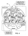
- FIGURE 4 illustrates a middle layer schematic of the LED tricolor power signal, in accordance with an aspect of the subject invention.
- FIGURE 5 illustrates a serpentine layer schematic of the LED tricolor power signal, in accordance with an aspect of the subject invention.
- FIGURE 6 illustrates a bottom layer schematic of the LED tricolor power signal, in accordance with an aspect of the subject invention.
- FIGURE 7 illustrates a rear view of the LED tricolor power signal sub assembly, in accordance with an aspect of the subject invention.
- FIGURE 8 illustrates a front view of the LED tricolor power signal sub assembly, in accordance with an aspect of the subject invention.
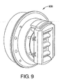
- FIGURE 9 illustrates a dummy load of the LED tricolor power signal sub assembly, in accordance with an aspect of the subject invention.
- FIG. 1 illustrates a block diagram of a light emitting diode (LED) tricolor power signal 100.
- the LED tricolor power signal 100 can be employed to provide control in a wide variety of applications such as a rail wayside signal, an automotive, rail, ship traffic and illumination signal, a rail searchlight, and/or one or more transit applications, for example.
- the LED tricolor signal 100 can include a plurality of benefits over conventional means such as high insulation between power circuits for each LED array, a light output detection, a single input connector (e.g., 12-pin) to provide seamless connection to conventional systems, a single output connector (12-pin) from power supplies to LED arrays (for all colors) to eliminate assembly errors, a dummy load (optional), a dummy load detection and a design that meets one or more industry standards, such as a safety integrity level 4.
- benefits over conventional means such as high insulation between power circuits for each LED array, a light output detection, a single input connector (e.g., 12-pin) to provide seamless connection to conventional systems, a single output connector (12-pin) from power supplies to LED arrays (for all colors) to eliminate assembly errors, a dummy load (optional), a dummy load detection and a design that meets one or more industry standards, such as a safety integrity level 4.
- the LED tricolor signal 100 can be employed to replace three conventional signal heads into a one integrated signal under one housing while maintaining safety and reliability requirements. Three colors can be utilized on a single LED board driven by three disparate power supplies to insure appropriate light output uniformity, fail safe and high insulation between all different colors. In this manner, failure from mechanical vibration is mitigated and cost associated with convention three head systems is reduced.
- LED lights for railway signs can be more robust than conventional systems. Moreover, a safer electronic base is employed that is capable of disabling a defective light under a wide variety potential electronic circuit degradation conditions.
- a safer electronic base is employed that is capable of disabling a defective light under a wide variety potential electronic circuit degradation conditions.
- To provide power to three LED arrays on a single head three power supplies are employed. Such design can minimize space requirements since only a single head is required.
- the tricolor power signal 100 can also provide uniform light intensity and beam angle while eliminating color mixing failure.
- the tricolor power signal 100 includes a power supply unit (PSU) 110, an LED light source array 120 and a monitoring circuit 130.
- the PSU 110 is representative of a plurality (e.g., three) of power supplies wherein each one drives a particular disparate LED array.
- the LED array 120 is similarly representative of one or more sets of LEDs that can correlate to a desired color and to the plurality of power supplies represented by the PSU 110.
- the monitoring circuit 130 can include a safeguarding circuit 212 (shown in FIG. 2 ) and a LED current detector circuit 228 (shown in FIG. 2 ) that monitors the current drawn by the LEDs and turns off permanently the input controlled switch 218 (see FIG. 2 ) by blowing a FBO fuse when the LEDs current is typically below twenty percent of its nominal value.
- the PCB LED light source array 120 can be, for example, a matrix of high-brightness 5 mm LEDs configured for redundancy. As will be described further below, the current flowing in the LEDs is regulated by the current sense feedback component 228 to provide constant light flux.
- the LED array 120 includes a pattern of four columns (one group of four LEDs connected in parallel) by twenty-two rows (twenty-two groups connected in series) for the Red LEDs, four by thirty-three for the Yellow LEDs and six by fifteen for the Green and White LEDs.
- the current is redistributed to the other LEDs of the same group and the signal maintains its light output.
- an increased current level is delivered to the remaining LEDs to compensate for the LEDs that have failed. In this manner, the light output level can be commensurate with that of a group with no LED failures.
- LED array 120 substantially any number of LEDs, with various colors in disparate configurations can be employed. In one approach, almost four hundred LEDs are arranged and placed on an LED board. Further, the circuits described herein can be arranged in substantially any manner utilizing various types of components (e.g., surface mount, through-hole, etc.). In one example, the tricolor power signal 100 control and power circuits are arranged in four stacked PCBs as depicted in FIGS. 3-6 below.
- FIG. 2 illustrates a schematic of the PSU 110 from FIG. 1 .
- An input filter 202 receives and filters line power which is received and ultimately delivered to the LED array 120. In this manner, the PSU 110 is protected against internal overload and/or a line voltage surge.
- the input filter 202 filters the switching frequency of the power stage input current in order to meet the EN55022 conducted and radiated Class B EMC.
- a fuse can provide protection against overload greater than a predetermined level (e.g., 3.5A) due to line surge.
- a predetermined level e.g., 3.5A
- the PSU 110 can withstand a surge of 2000 volt 1.2/50us open circuit voltage and an 8/20us short circuit current surge having a source impedance of 2 ohms.
- a varistor (not shown) can clamp the input voltage to a predetermined level (e.g., 10/120V/220V) when a power surge is detected.
- Power is drawn from the input filter 202 by a main flyback insulated transformer 204, a dummy load resistor 236, and the safeguarding circuit 212.
- the main flyback insulated transformer 204 converts the input power into a form utilized by the LEDs load 120.
- the dummy load resistor 236 is employed to provide an additional current draw to allow the LED signal 100 to be employed as a replacement for conventional incandescent systems. As known, LED signals draw much less current than conventional systems and such compensation can allow LED signals to be implemented seamlessly as viewed by conventional control systems.
- the safeguarding circuit 212 is employed to prevent deleterious effects caused by undesired power fluctuations in the PSU 110.
- the safeguarding circuit 212 can be employed to force a fuse to blow out when the power drawn by the LED array 120 is lower than a predetermined threshold (e.g., twenty percent of its nominal value). If such a threshold is met, the connection to power will be opened.
- a time delay circuit can be employed to provide a sufficient delay to the PSU 110 to turn on (e.g., 50ms to 170 ms) which is and sufficiently short to blow a fuse when the signal 100 is in flashing mode (e.g., 330 ms).
- the input current is converted via a main flyback insulated transformer 204 from an input AC or DC power to a constant DC output to power the LED array 120.
- the main flyback insulated transformer 204 is a switch-mode converter that transforms 10V/120V/240V, AC or DC voltage to a DC current. In this manner, the LED array 120 can emit continuous light with no flicker.
- a flyback converter topology can be employed to provide specific voltage across the LED array 120 based on a desired LED configuration. Such configuration can vary based on quantity, configuration and/or type of LED employed.
- the input under-voltage circuit 216 receives power from the input filter 202 to monitor the line voltage level. In one example, the input under-voltage circuit 216 will activate the input controlled switch 218 to let the power go from the line to the LED's.
- the safeguarding circuit 212 blows out the fuse to disable the input controlled switch 218 if no current flows through the LED array after a predetermined time when the input controlled switch 218 is activated. Alternatively or in addition, the safeguarding circuit 212 can disable the input power to the LED array if the light output is less than a predetermined threshold.
- a serpentine trace 214 can be connected in series with the fuse of the safeguarding circuit 212 to disable the input controlled switch 218 upon physical damage to the PCB (power supply).
- the serpentine trace 214 is laid in a pattern to cover substantially the entire surface area of the PCB. Thus, if the PCB is physically damaged, the serpentine trace 214 will be broken and the signal will be disabled. In this manner, the serpentine trace 214 provides an additional safety measure to insure the signal is working properly and is not illuminated erroneously.
- An input under voltage circuit 216 receives an input from the power line via the safeguarding circuit 212 to disable the input controlled switch 218 if the power line voltage is less than a predetermined threshold.
- the input controlled switch 218 can convert a voltage (e.g., 10 V/120V/240V, AC or DC) to a predetermined output constant current to the LED array 120.
- Railroads safety issue requires a circuit to control the turn-on and turn-off of the LED array 120.
- the implementation of the input controlled switch 218 of the PSU 110 can provide such protection against an out of range low input voltage.
- the input controlled switch 218 has a turn-on feature that monitors the input line voltage.
- the LED array 120 is turned on at a predetermined voltage level and turned off at another predetermined voltage level. In this manner, the input controlled switch 218 can be designed to turn on when the input line voltage exceeds the minimum turn-on level and turns off below the maximum turn-off level to provide sufficient margins.
- a cold filament test circuit 222 between the input controlled switch 218 and the input power.
- the cold filament test circuit 222 is connected to the power line to emulate an impedance of an incandescent light during a power stage set-up time during which no current is supplied to the LED array.
- the cold filament test circuit 222 can be employed in conventional signals to verify if a filament of the incandescent lamp is open or not. In this manner, the system controller can supply the lamp for 2 ms to check the lamp current. Since 2 ms is too short for an incandescent lamp to radiate light this approach is sufficient to validate its status. The same test may be performed on the LED array 120.
- the input current is monitored. After the application of the input voltage the current must be greater than a predetermined value, otherwise the test fails.
- the load current of the cold filament test circuit 222 combined with the dummy load current and the inrush current of the input power supply filter capacitor during turn-on provides the necessary current at lower turn-on voltage. In normal operation during turn-on, the cold filament test circuit 222 stays enabled until twenty percent of the LED current is reached. Then, the cold filament test circuit 222 is disabled.
- a start-up circuit 220 has an input connected to the input controlled switch 218 and an output connected to the control circuit for starting up the module.
- the start-up circuit 220 is a switch-mode boost converter that uses the voltage across the capacitor to generate a reference voltage.
- the duty cycle is constant and set to get an output voltage necessary for the PWM for a predetermined minimum input voltage.
- a pulse width modulator (PWM) needs 15V to start up.
- the start-up circuit 220 stays enabled until twenty percent of the current delivered to the LED array 120 is reached.
- a bleeder circuit 230 is coupled between the control component 208 and the LED array 120.
- the bleeder circuit 230 is coupled between the control circuit 208 and the LED array 120 to shorten the delay between power down initiation and shut down of the LED array 120.
- the bleeder circuit 230 can utilize a peak voltage detector to monitor the switching waveform voltage of a transformer. At turn-off, the switching waveform voltage can be eliminated wherein a resistor (e.g., 1 Kohm) is shunted across an output capacitor to force an accelerated power discharge (e.g., less than 75 msec). Without the bleeder circuit 230, power to the LEDs load 120 would discharge at a constant rate established by the characteristic V F - I F of the LEDs down to a minimum voltage level. In this manner, upon turn off the LEDs will not continue to emit light after turn off.
- a resistor e.g. 1 Kohm
- a control circuit 208 allows the flyback transformer 204 to deliver and regulate the power to the LED array.
- An output over voltage protection circuit 224 receives an input from the control circuit 208 to activate the safeguarding circuit 212 if the power line voltage is greater than a predetermined threshold.
- a flyback power switch 206 regulates power output from the flyback transformer 204 to the LED array 120 based on input from the control circuit 208.
- An output filter component 232 receives input from the flyback transformer 204 to the LED array 120.
- the output filter 232 filters power delivered from the flyback transformer 204 to the LED array 120. In this manner, the output filter 232 provides protection against output current ripple.
- the input line current is monitored by the light out detection circuit 226 that monitors whether the LED array is functional.
- the tricolor power signal 100 module detects a light out condition if the LEDs current is below a predetermined value.
- the PSU 110 regulates the current delivered to the LED array 120 to maintain constant light intensity.
- the flyback transformer 204 provides output constant power and assuming that the internal losses are almost constant for different input voltage conditions, it could be assumed that the input power delivered to the PSU 110 is constant. Having a constant input power, the line current amplitude is higher at a lower input voltage and lower at a higher input voltage. In terms of input impedance, the PSU 18 has a negative slope resistance.
- a dummy load resistor 236 can be added across the input power line to cancel out the negative slope effect of the PSU's 110 input impedance.
- the input controlled switch 218 isolates the dummy load 236 when the PSU 110 is off. In this manner, the power drawn by the LED array 120 is supplemented via the dummy load 236 to emulate the power of an incandescent signal. Such current draw will therefore trigger the same threshold levels as the original control system thereby eliminating the need to reconfigure the legacy control system.
- a dummy load detection circuit 210 can be employed to verify that the dummy load is drawing an appropriate current level according to one or more predetermined thresholds.
- the dummy load detection circuit 210 receives an input from the dummy load 236 and provides an output to the safeguarding circuit 212 if an error condition exists to discontinue power delivery to the PSU 110.
- the addition of the dummy load 236 and the dummy load detection circuit 210 can allow the design to avoid being downgraded by AREMA-specified controller (or equivalent) due to variation in input current from an incandescent signal to an LED signal.
- An LED current sense feedback circuit 228 can be employed to verify that the current drawn by the LED array 120 is within acceptable operating parameters. If the current is below a predetermined threshold, the safeguarding circuit 212 can be activated to disable power delivery when the current of the LED array 120 reaches a predetermined current level. In one example, the LED current sense feedback circuit 228 disables the safeguarding circuit 212, when the LED current goes below a predetermined threshold. If the LED current does not reach a predetermined threshold within a predetermined time delay, then the safeguarding circuit 212 blows out a fuse and the PSU 110 turns off.
- a light output detection circuit 226 can monitor light output by the LED array 120.
- the light output detection circuit 226 can be connected between the LED load 120 and the safeguarding circuit 212 wherein the light out detection circuit 226 is activated when the light output is below a predetermined threshold.
- An optical element such as a CCD array can be utilized to monitor the light output of the LED array 120.
- the above control circuitry can mitigate potential hazard situations that may occur.
- Some situations can include an undetectable dark lamp, flashing in steady mode, a lamp which is perceived to be lit as steady when it should be perceived as flashing and/or immunity to SSC's check pulses (e.g., 16V, 2ms pulses).
- FIG. 3 Illustrates a top layer 300 of a PCB stack that is employed to implement the tricolor power signal 100.
- the top layer includes a primary side 305 and a secondary side 340.
- the primary side 305 includes the power supply unit 110 and the secondary side 340 includes the LED array 120.
- the power supply unit 110 for the LED array 120 includes one for each of a red LED group 310, a yellow LED group 320 and a green LED group 330 and are included in the primary side 305.
- the primary side 305 is insulated from the secondary side 340 by a minimum of 3kV.
- FIGS. 4 , 5 , and 6 illustrate a middle layer 400, a serpentine layer 500 and a bottom layer 600 respectively of the tricolor power signal 100.
- the layers can be stacked from top to bottom with layer 300 on top and layers 400, 500, and 600 stacked consecutively underneath 300.
- the serpentine layer 500 can be employed to disable power to the tricolor power signal 100 if physical damage occurs. This safety measure is equivalent to blowing a fuse to ensure detection of a dark signal in such a case.
- FIGS. 7 , 8 , and 9 illustrate a rear exploded view 700, a front exploded view 800, and a rear isometric view 900 of the tricolor power signal 100.
- back assembly of the tricolor power signal 100 can insure water tightness, dielectric clearance and ease of assembly.
- One or more gaskets (not shown) can be employed to prevent exposure of the electrical connections to water or particulate matter.
- the dummy loads can be arranged In a parallel configuration, as shown, to ease assembly and to insure that no accidental contact with dummy load terminals occurs.
- the location of the power supplies for each of the three LED groups can be designed in accordance with safety recommendations from AREMA related to vital trace spacing.
- the circuit as described herein does not have a single point of failure to provide a more robust design than conventional means.
- the PSU 110 has very quick input current time response to make signal compatible to substantially any automotive, rail, ship traffic and illumination controller specified by AREMA, ITE or specified by European standards. Moreover, the PSU 110 is designed in such a manner that one cannot misconnect the colors. A unique output connector (e.g., 12-pin) can be keyed to insure that only one interface orientation is possible.
- a unique output connector e.g., 12-pin
- the PSU 110 layout includes an insulated converter in order to insulate electrically the three different colors, even if the LED board itself is not insulated against 3kV.
- the PSU 110 layout is arranged in such a manner as to avoid any of the IC's having single point failures. In this manner, whatever the failure on the IC, the consequence will never be a simultaneous deactivation of the safety circuit and/or erroneous lighting of the LED array.
- the PSU 110 is designed such that the safeguarding circuit 212 is always active, whatever the failures.
- sun phantom reduction devices can be utilized in accordance with the tricolor power signal 100.
Landscapes
- Engineering & Computer Science (AREA)
- Mechanical Engineering (AREA)
- Circuit Arrangement For Electric Light Sources In General (AREA)
- Lighting Device Outwards From Vehicle And Optical Signal (AREA)
Applications Claiming Priority (1)
| Application Number | Priority Date | Filing Date | Title |
|---|---|---|---|
| US12/006,143 US7696698B2 (en) | 2007-12-31 | 2007-12-31 | LEDs tricolor power signal |
Publications (3)
| Publication Number | Publication Date |
|---|---|
| EP2076095A2 true EP2076095A2 (fr) | 2009-07-01 |
| EP2076095A3 EP2076095A3 (fr) | 2011-03-30 |
| EP2076095B1 EP2076095B1 (fr) | 2013-10-30 |
Family
ID=40564881
Family Applications (1)
| Application Number | Title | Priority Date | Filing Date |
|---|---|---|---|
| EP08254135.0A Not-in-force EP2076095B1 (fr) | 2007-12-31 | 2008-12-23 | Feu de signalisation tricolore à DEL |
Country Status (3)
| Country | Link |
|---|---|
| US (1) | US7696698B2 (fr) |
| EP (1) | EP2076095B1 (fr) |
| AU (1) | AU2008264218B2 (fr) |
Cited By (15)
| Publication number | Priority date | Publication date | Assignee | Title |
|---|---|---|---|---|
| FR2968886A1 (fr) * | 2010-12-13 | 2012-06-15 | Schneider Electric Ind Sas | Dispositif et procede de diagnostic pour systeme d'eclairage a diodes electroluminescentes et ensemble d'eclairage comportant un tel dispositif |
| CN102548159A (zh) * | 2010-12-28 | 2012-07-04 | 通用电气照明解决方案有限责任公司 | 用于交通灯的安全闪烁检测器 |
| EP2506685A1 (fr) * | 2010-12-02 | 2012-10-03 | Smar Analog Technology Co., Ltd | Circuit d'alimentation électrique pour excitation de diodes électroluminescentes, alimentation électrique d'excitation, et dispositif d'éclairage |
| WO2012167292A1 (fr) * | 2011-06-08 | 2012-12-13 | Tridonic Gmbh & Co. Kg | Procédé de fonctionnement d'un ballast électronique pour un luminaire, ainsi que ballast électronique |
| GB2495120A (en) * | 2011-09-29 | 2013-04-03 | Howells Group Plc | Railway light signals |
| FR2987679A1 (fr) * | 2012-03-01 | 2013-09-06 | Aximum | Dispositif et procede de generation d'une consommation augmentee d'un appareillage electrique, application a un feu de signalisation routiere |
| CN103458557A (zh) * | 2012-05-31 | 2013-12-18 | 海洋王照明科技股份有限公司 | 一种led驱动控制电路及led灯具 |
| EP2938164A3 (fr) * | 2014-04-24 | 2015-12-09 | Power Integrations, Inc. | Commande de mode multi-drainage pour une meilleure performance de commande de led |
| EP2768284A3 (fr) * | 2013-02-15 | 2016-02-24 | GE Lighting Solutions, LLC | Circuit de charge supplémentaire pour lampes de trafic à faible puissance |
| EP3037713A1 (fr) * | 2014-12-23 | 2016-06-29 | DB Netz AG | Dispositif d'eclairage pour une installation de signal lumineux du trafic ferroviaire |
| CN107517509A (zh) * | 2016-06-15 | 2017-12-26 | 刘志锋 | 一种节能高效的大功率led‑uv灯控制系统 |
| WO2018091900A1 (fr) * | 2016-11-18 | 2018-05-24 | Saf-T-Glo Limited | Bloc d'éclairage de rétroinstallation à del |
| WO2018108826A1 (fr) * | 2016-12-16 | 2018-06-21 | Philips Lighting Holding B.V. | Diode électroluminescente, del, à installation retroactive, tube de connexion à un ballast électronique, et système d'éclairage correspondant et procédé |
| CN112678028A (zh) * | 2021-01-19 | 2021-04-20 | 中车青岛四方车辆研究所有限公司 | 自动减载方法、自动减载系统 |
| GB2625522A (en) * | 2022-12-15 | 2024-06-26 | Robert Pearson Stephen | Traffic signals halogen to LED conversion system |
Families Citing this family (16)
| Publication number | Priority date | Publication date | Assignee | Title |
|---|---|---|---|---|
| JP4258500B2 (ja) * | 2005-07-28 | 2009-04-30 | サンケン電気株式会社 | 放電灯点灯装置 |
| US8294371B2 (en) | 2009-08-17 | 2012-10-23 | GE Lighting Solutions, LLC | LED traffic signal with synchronized power pulse circuit |
| US8686668B2 (en) | 2009-10-26 | 2014-04-01 | Koninklijke Philips N.V. | Current offset circuits for phase-cut power control |
| US8283875B2 (en) | 2009-10-26 | 2012-10-09 | Light-Based Technologies Incorporated | Holding current circuits for phase-cut power control |
| CN102109583B (zh) * | 2009-12-25 | 2013-09-18 | 上海康耐司信号设备有限公司 | 一种集成led转向灯的假负载系统 |
| DE102010005088A1 (de) * | 2010-01-15 | 2011-07-21 | Siemens Aktiengesellschaft, 80333 | Lichtsignal |
| DE102010015908B4 (de) * | 2010-03-10 | 2013-10-24 | Lear Corporation Gmbh | Vorrichtung zur Ansteuerung einer elektrischen Last |
| US8659232B2 (en) | 2010-09-14 | 2014-02-25 | Crs Electronics | Variable-impedance load for LED lamps |
| CN102457049B (zh) | 2010-10-29 | 2014-07-02 | 登丰微电子股份有限公司 | 电源转换控制器及发光二极管驱动电路 |
| JP5910814B2 (ja) * | 2011-12-26 | 2016-04-27 | 東芝ライテック株式会社 | 電力変換装置 |
| US8974077B2 (en) | 2012-07-30 | 2015-03-10 | Ultravision Technologies, Llc | Heat sink for LED light source |
| KR101284156B1 (ko) * | 2012-12-11 | 2013-07-10 | 고인홍 | 독자적으로 점소등되는 led어레이들을 갖는 led 조명장치 |
| JP2017131033A (ja) * | 2016-01-20 | 2017-07-27 | 株式会社デンソー | スイッチング電源装置 |
| CN107548188B (zh) * | 2016-06-24 | 2024-05-24 | 富满微电子集团股份有限公司 | 一种led灯、led色温调节控制芯片及电路 |
| GB2566485B (en) * | 2017-09-14 | 2020-04-29 | Unipart Rail Ltd | Rail signal arrangement for a rail signalling system |
| CN115303326B (zh) * | 2022-08-02 | 2023-10-27 | 北京全路通信信号研究设计院集团有限公司 | 一种信号灯、系统及控制方法 |
Citations (3)
| Publication number | Priority date | Publication date | Assignee | Title |
|---|---|---|---|---|
| WO2004075606A1 (fr) | 2003-02-20 | 2004-09-02 | Gelcore Llc | Module d'alimentation et de controle de diodes electroluminescentes |
| DE10359196A1 (de) | 2003-12-17 | 2005-07-21 | Hella Kgaa Hueck & Co. | Leuchtmittelanordnung und Beleuchtungseinrichtung für ein Kraftfahrzeug |
| GB2429542A (en) | 2005-08-25 | 2007-02-28 | Lights And Signals Ltd | Lamp emulation circuit |
Family Cites Families (19)
| Publication number | Priority date | Publication date | Assignee | Title |
|---|---|---|---|---|
| US3946209A (en) * | 1974-10-07 | 1976-03-23 | Hewlett-Packard Company | High frequency counter having signal level sensitivity |
| CA2225005A1 (fr) * | 1997-12-17 | 1999-06-17 | Gelcore Llc | Voyant del avec circuit indicateur de pannes et dont l'impedance varie |
| KR20000005571A (ko) * | 1998-06-03 | 2000-01-25 | 유길수 | 문자및/또는영상표시장치및방법 |
| US6693556B1 (en) | 1998-07-13 | 2004-02-17 | Blinkerstop Llc | Enhanced visibility traffic signal |
| CA2337057C (fr) | 1998-07-13 | 2005-03-29 | Blinkerstop, Llc | Dispositif de signalisation routiere a visibilite amelioree |
| US6054932A (en) | 1998-11-20 | 2000-04-25 | Gartner; William J. | LED traffic light and method manufacture and use thereof |
| US6567010B1 (en) | 2000-03-31 | 2003-05-20 | Fong-Jei Lin | Traffic signal head with multiple LED illumination sources |
| US6555958B1 (en) | 2000-05-15 | 2003-04-29 | General Electric Company | Phosphor for down converting ultraviolet light of LEDs to blue-green light |
| US6466135B1 (en) | 2000-05-15 | 2002-10-15 | General Electric Company | Phosphors for down converting ultraviolet light of LEDs to blue-green light |
| US6621211B1 (en) | 2000-05-15 | 2003-09-16 | General Electric Company | White light emitting phosphor blends for LED devices |
| US6474839B1 (en) | 2000-10-05 | 2002-11-05 | Power Signal Technology Inc. | LED based trough designed mechanically steerable beam traffic signal |
| EP1286321A1 (fr) | 2001-08-20 | 2003-02-26 | Lin; Fong-Jei | Feu de circulation avec plusieurs sources d'illumination DEL |
| CA2404905A1 (fr) * | 2001-11-28 | 2003-05-28 | Gelcore, Llc | Methode et dispositif de telesurveillance de lampes a del |
| US7102538B2 (en) | 2004-04-05 | 2006-09-05 | Kuo-Chin Chen | LED signal light |
| US7490954B2 (en) | 2004-07-30 | 2009-02-17 | Lumination Llc | LED traffic signal |
| US7321191B2 (en) | 2004-11-02 | 2008-01-22 | Lumination Llc | Phosphor blends for green traffic signals |
| KR200397860Y1 (ko) | 2005-01-04 | 2005-10-10 | 종 해 김 | 다목적 led 보행자 신호등 시스템과 장치 |
| US20070114562A1 (en) | 2005-11-22 | 2007-05-24 | Gelcore, Llc | Red and yellow phosphor-converted LEDs for signal applications |
| JP4869744B2 (ja) * | 2006-03-09 | 2012-02-08 | 株式会社 日立ディスプレイズ | Led照明装置及びこれを用いた液晶表示装置 |
-
2007
- 2007-12-31 US US12/006,143 patent/US7696698B2/en active Active
-
2008
- 2008-12-23 EP EP08254135.0A patent/EP2076095B1/fr not_active Not-in-force
- 2008-12-24 AU AU2008264218A patent/AU2008264218B2/en not_active Ceased
Patent Citations (3)
| Publication number | Priority date | Publication date | Assignee | Title |
|---|---|---|---|---|
| WO2004075606A1 (fr) | 2003-02-20 | 2004-09-02 | Gelcore Llc | Module d'alimentation et de controle de diodes electroluminescentes |
| DE10359196A1 (de) | 2003-12-17 | 2005-07-21 | Hella Kgaa Hueck & Co. | Leuchtmittelanordnung und Beleuchtungseinrichtung für ein Kraftfahrzeug |
| GB2429542A (en) | 2005-08-25 | 2007-02-28 | Lights And Signals Ltd | Lamp emulation circuit |
Cited By (24)
| Publication number | Priority date | Publication date | Assignee | Title |
|---|---|---|---|---|
| EP2506685A1 (fr) * | 2010-12-02 | 2012-10-03 | Smar Analog Technology Co., Ltd | Circuit d'alimentation électrique pour excitation de diodes électroluminescentes, alimentation électrique d'excitation, et dispositif d'éclairage |
| EP2506685A4 (fr) * | 2010-12-02 | 2013-10-16 | Sunsun Lighting China Co Ltd | Circuit d'alimentation électrique pour excitation de diodes électroluminescentes, alimentation électrique d'excitation, et dispositif d'éclairage |
| FR2968886A1 (fr) * | 2010-12-13 | 2012-06-15 | Schneider Electric Ind Sas | Dispositif et procede de diagnostic pour systeme d'eclairage a diodes electroluminescentes et ensemble d'eclairage comportant un tel dispositif |
| CN102548159A (zh) * | 2010-12-28 | 2012-07-04 | 通用电气照明解决方案有限责任公司 | 用于交通灯的安全闪烁检测器 |
| EP2473005A3 (fr) * | 2010-12-28 | 2012-11-28 | GE Lighting Solutions, LLC | Détecteur clignotant de sécurité pour phares |
| CN102548159B (zh) * | 2010-12-28 | 2016-06-08 | 通用电气照明解决方案有限责任公司 | 用于交通灯的安全闪烁检测器 |
| WO2012167292A1 (fr) * | 2011-06-08 | 2012-12-13 | Tridonic Gmbh & Co. Kg | Procédé de fonctionnement d'un ballast électronique pour un luminaire, ainsi que ballast électronique |
| GB2495120B (en) * | 2011-09-29 | 2015-11-18 | Howells Group Plc | Railway light signals |
| GB2495120A (en) * | 2011-09-29 | 2013-04-03 | Howells Group Plc | Railway light signals |
| FR2987679A1 (fr) * | 2012-03-01 | 2013-09-06 | Aximum | Dispositif et procede de generation d'une consommation augmentee d'un appareillage electrique, application a un feu de signalisation routiere |
| CN103458557A (zh) * | 2012-05-31 | 2013-12-18 | 海洋王照明科技股份有限公司 | 一种led驱动控制电路及led灯具 |
| EP2768284A3 (fr) * | 2013-02-15 | 2016-02-24 | GE Lighting Solutions, LLC | Circuit de charge supplémentaire pour lampes de trafic à faible puissance |
| EP2938164A3 (fr) * | 2014-04-24 | 2015-12-09 | Power Integrations, Inc. | Commande de mode multi-drainage pour une meilleure performance de commande de led |
| US9402293B2 (en) | 2014-04-24 | 2016-07-26 | Power Integrations, Inc. | Multi-bleeder mode control for improved LED driver performance |
| EP3037713A1 (fr) * | 2014-12-23 | 2016-06-29 | DB Netz AG | Dispositif d'eclairage pour une installation de signal lumineux du trafic ferroviaire |
| CN107517509A (zh) * | 2016-06-15 | 2017-12-26 | 刘志锋 | 一种节能高效的大功率led‑uv灯控制系统 |
| WO2018091900A1 (fr) * | 2016-11-18 | 2018-05-24 | Saf-T-Glo Limited | Bloc d'éclairage de rétroinstallation à del |
| GB2571495A (en) * | 2016-11-18 | 2019-08-28 | Saf T Glo Ltd | LED retrofit lighting unit |
| US10807524B2 (en) | 2016-11-18 | 2020-10-20 | Saf-T-Glo Limited | Lighting unit |
| US10981498B2 (en) | 2016-11-18 | 2021-04-20 | Saf-T-Glo Limited | LED retrofit lighting unit |
| GB2571495B (en) * | 2016-11-18 | 2022-06-15 | Saf T Glo Ltd | Lighting unit |
| WO2018108826A1 (fr) * | 2016-12-16 | 2018-06-21 | Philips Lighting Holding B.V. | Diode électroluminescente, del, à installation retroactive, tube de connexion à un ballast électronique, et système d'éclairage correspondant et procédé |
| CN112678028A (zh) * | 2021-01-19 | 2021-04-20 | 中车青岛四方车辆研究所有限公司 | 自动减载方法、自动减载系统 |
| GB2625522A (en) * | 2022-12-15 | 2024-06-26 | Robert Pearson Stephen | Traffic signals halogen to LED conversion system |
Also Published As
| Publication number | Publication date |
|---|---|
| US20090167186A1 (en) | 2009-07-02 |
| AU2008264218B2 (en) | 2014-08-07 |
| AU2008264218A1 (en) | 2009-07-16 |
| EP2076095B1 (fr) | 2013-10-30 |
| EP2076095A3 (fr) | 2011-03-30 |
| US7696698B2 (en) | 2010-04-13 |
Similar Documents
| Publication | Publication Date | Title |
|---|---|---|
| US7696698B2 (en) | LEDs tricolor power signal | |
| US6762563B2 (en) | Module for powering and monitoring light-emitting diodes | |
| US9668308B2 (en) | Linear solid-state lighting compatible with ballasts in double ends and operable with AC mains in a single end | |
| JP4952292B2 (ja) | Led点灯装置及び照明装置システム | |
| US20050062481A1 (en) | Wayside LED signal for railroad and transit applications | |
| US8390216B2 (en) | Apparatus and method for a light-emitting diode lamp that simulates a filament lamp | |
| CN105715979B (zh) | 无起火和电击危险的线性固态照明 | |
| US8294371B2 (en) | LED traffic signal with synchronized power pulse circuit | |
| JP2008131007A (ja) | 発光回路及びこれを備えた照明装置 | |
| JP2008251227A (ja) | 発光装置 | |
| US9544959B2 (en) | Solid-state lighting compatible with ballasts and operable with AC mains | |
| JP2014191933A (ja) | 標識灯装置 | |
| EP1916879B1 (fr) | Détection de défaillance secure pour des LED à puissance elevée | |
| KR101631407B1 (ko) | 직류/교류 겸용 안정기의 상태를 판단하는 장치 및 방법 | |
| US20020101362A1 (en) | Backup traffic control in the event of power failure | |
| JP5693264B2 (ja) | 調光装置及び照明器具 | |
| WO2020231298A1 (fr) | Module de feu de signalisation | |
| EP3089556B1 (fr) | Lampe d'éclairage, appareil d'éclairage et circuit de commande d'éclairage | |
| JP6369689B2 (ja) | 標識灯および標識灯システム | |
| KR200310502Y1 (ko) | 가로등의 전구단락 및 과전류 검출장치 | |
| CN108882455B (zh) | 具有无起火危险的可靠电击电流控制的线性固态照明 | |
| JP2017174680A (ja) | Ledランプ及びled照明装置 | |
| US20150312976A1 (en) | Low Power Bypass Circuit for LED Open Circuit and Reverse Polarity Protection | |
| KR101219993B1 (ko) | 전원 공급 장치 | |
| PL235568B1 (pl) | Sposób sterowania i kontroli źródeł światła LED w sygnalizacji kolejowej i drogowej |
Legal Events
| Date | Code | Title | Description |
|---|---|---|---|
| PUAI | Public reference made under article 153(3) epc to a published international application that has entered the european phase |
Free format text: ORIGINAL CODE: 0009012 |
|
| AK | Designated contracting states |
Kind code of ref document: A2 Designated state(s): AT BE BG CH CY CZ DE DK EE ES FI FR GB GR HR HU IE IS IT LI LT LU LV MC MT NL NO PL PT RO SE SI SK TR |
|
| AX | Request for extension of the european patent |
Extension state: AL BA MK RS |
|
| PUAL | Search report despatched |
Free format text: ORIGINAL CODE: 0009013 |
|
| AK | Designated contracting states |
Kind code of ref document: A3 Designated state(s): AT BE BG CH CY CZ DE DK EE ES FI FR GB GR HR HU IE IS IT LI LT LU LV MC MT NL NO PL PT RO SE SI SK TR |
|
| AX | Request for extension of the european patent |
Extension state: AL BA MK RS |
|
| RIC1 | Information provided on ipc code assigned before grant |
Ipc: B61L 5/18 20060101ALI20110223BHEP Ipc: H05B 33/08 20060101AFI20090427BHEP |
|
| RAP1 | Party data changed (applicant data changed or rights of an application transferred) |
Owner name: GE LIGHTING SOLUTIONS, LLC |
|
| 17P | Request for examination filed |
Effective date: 20110929 |
|
| RIC1 | Information provided on ipc code assigned before grant |
Ipc: B61L 5/18 20060101ALI20111027BHEP Ipc: H05B 33/08 20060101AFI20111027BHEP |
|
| AKX | Designation fees paid |
Designated state(s): AT BE BG CH CY CZ DE DK EE ES FI FR GB GR HR HU IE IS IT LI LT LU LV MC MT NL NO PL PT RO SE SI SK TR |
|
| GRAP | Despatch of communication of intention to grant a patent |
Free format text: ORIGINAL CODE: EPIDOSNIGR1 |
|
| GRAS | Grant fee paid |
Free format text: ORIGINAL CODE: EPIDOSNIGR3 |
|
| GRAJ | Information related to disapproval of communication of intention to grant by the applicant or resumption of examination proceedings by the epo deleted |
Free format text: ORIGINAL CODE: EPIDOSDIGR1 |
|
| 17Q | First examination report despatched |
Effective date: 20120921 |
|
| GRAP | Despatch of communication of intention to grant a patent |
Free format text: ORIGINAL CODE: EPIDOSNIGR1 |
|
| INTG | Intention to grant announced |
Effective date: 20130409 |
|
| GRAS | Grant fee paid |
Free format text: ORIGINAL CODE: EPIDOSNIGR3 |
|
| GRAA | (expected) grant |
Free format text: ORIGINAL CODE: 0009210 |
|
| AK | Designated contracting states |
Kind code of ref document: B1 Designated state(s): AT BE BG CH CY CZ DE DK EE ES FI FR GB GR HR HU IE IS IT LI LT LU LV MC MT NL NO PL PT RO SE SI SK TR |
|
| REG | Reference to a national code |
Ref country code: GB Ref legal event code: FG4D |
|
| REG | Reference to a national code |
Ref country code: CH Ref legal event code: EP |
|
| REG | Reference to a national code |
Ref country code: AT Ref legal event code: REF Ref document number: 638786 Country of ref document: AT Kind code of ref document: T Effective date: 20131115 |
|
| REG | Reference to a national code |
Ref country code: IE Ref legal event code: FG4D |
|
| REG | Reference to a national code |
Ref country code: DE Ref legal event code: R096 Ref document number: 602008028408 Country of ref document: DE Effective date: 20131224 |
|
| REG | Reference to a national code |
Ref country code: NL Ref legal event code: VDEP Effective date: 20131030 |
|
| REG | Reference to a national code |
Ref country code: AT Ref legal event code: MK05 Ref document number: 638786 Country of ref document: AT Kind code of ref document: T Effective date: 20131030 |
|
| REG | Reference to a national code |
Ref country code: LT Ref legal event code: MG4D |
|
| PG25 | Lapsed in a contracting state [announced via postgrant information from national office to epo] |
Ref country code: FI Free format text: LAPSE BECAUSE OF FAILURE TO SUBMIT A TRANSLATION OF THE DESCRIPTION OR TO PAY THE FEE WITHIN THE PRESCRIBED TIME-LIMIT Effective date: 20131030 Ref country code: IS Free format text: LAPSE BECAUSE OF FAILURE TO SUBMIT A TRANSLATION OF THE DESCRIPTION OR TO PAY THE FEE WITHIN THE PRESCRIBED TIME-LIMIT Effective date: 20140228 Ref country code: LT Free format text: LAPSE BECAUSE OF FAILURE TO SUBMIT A TRANSLATION OF THE DESCRIPTION OR TO PAY THE FEE WITHIN THE PRESCRIBED TIME-LIMIT Effective date: 20131030 Ref country code: NO Free format text: LAPSE BECAUSE OF FAILURE TO SUBMIT A TRANSLATION OF THE DESCRIPTION OR TO PAY THE FEE WITHIN THE PRESCRIBED TIME-LIMIT Effective date: 20140130 Ref country code: HR Free format text: LAPSE BECAUSE OF FAILURE TO SUBMIT A TRANSLATION OF THE DESCRIPTION OR TO PAY THE FEE WITHIN THE PRESCRIBED TIME-LIMIT Effective date: 20131030 Ref country code: BE Free format text: LAPSE BECAUSE OF FAILURE TO SUBMIT A TRANSLATION OF THE DESCRIPTION OR TO PAY THE FEE WITHIN THE PRESCRIBED TIME-LIMIT Effective date: 20131030 Ref country code: SE Free format text: LAPSE BECAUSE OF FAILURE TO SUBMIT A TRANSLATION OF THE DESCRIPTION OR TO PAY THE FEE WITHIN THE PRESCRIBED TIME-LIMIT Effective date: 20131030 Ref country code: NL Free format text: LAPSE BECAUSE OF FAILURE TO SUBMIT A TRANSLATION OF THE DESCRIPTION OR TO PAY THE FEE WITHIN THE PRESCRIBED TIME-LIMIT Effective date: 20131030 |
|
| PG25 | Lapsed in a contracting state [announced via postgrant information from national office to epo] |
Ref country code: ES Free format text: LAPSE BECAUSE OF FAILURE TO SUBMIT A TRANSLATION OF THE DESCRIPTION OR TO PAY THE FEE WITHIN THE PRESCRIBED TIME-LIMIT Effective date: 20131030 Ref country code: AT Free format text: LAPSE BECAUSE OF FAILURE TO SUBMIT A TRANSLATION OF THE DESCRIPTION OR TO PAY THE FEE WITHIN THE PRESCRIBED TIME-LIMIT Effective date: 20131030 Ref country code: LV Free format text: LAPSE BECAUSE OF FAILURE TO SUBMIT A TRANSLATION OF THE DESCRIPTION OR TO PAY THE FEE WITHIN THE PRESCRIBED TIME-LIMIT Effective date: 20131030 Ref country code: CY Free format text: LAPSE BECAUSE OF FAILURE TO SUBMIT A TRANSLATION OF THE DESCRIPTION OR TO PAY THE FEE WITHIN THE PRESCRIBED TIME-LIMIT Effective date: 20131030 |
|
| PG25 | Lapsed in a contracting state [announced via postgrant information from national office to epo] |
Ref country code: PT Free format text: LAPSE BECAUSE OF FAILURE TO SUBMIT A TRANSLATION OF THE DESCRIPTION OR TO PAY THE FEE WITHIN THE PRESCRIBED TIME-LIMIT Effective date: 20140228 |
|
| PG25 | Lapsed in a contracting state [announced via postgrant information from national office to epo] |
Ref country code: MC Free format text: LAPSE BECAUSE OF FAILURE TO SUBMIT A TRANSLATION OF THE DESCRIPTION OR TO PAY THE FEE WITHIN THE PRESCRIBED TIME-LIMIT Effective date: 20131030 Ref country code: EE Free format text: LAPSE BECAUSE OF FAILURE TO SUBMIT A TRANSLATION OF THE DESCRIPTION OR TO PAY THE FEE WITHIN THE PRESCRIBED TIME-LIMIT Effective date: 20131030 |
|
| REG | Reference to a national code |
Ref country code: CH Ref legal event code: PL Ref country code: DE Ref legal event code: R097 Ref document number: 602008028408 Country of ref document: DE |
|
| PG25 | Lapsed in a contracting state [announced via postgrant information from national office to epo] |
Ref country code: PL Free format text: LAPSE BECAUSE OF FAILURE TO SUBMIT A TRANSLATION OF THE DESCRIPTION OR TO PAY THE FEE WITHIN THE PRESCRIBED TIME-LIMIT Effective date: 20131030 Ref country code: CZ Free format text: LAPSE BECAUSE OF FAILURE TO SUBMIT A TRANSLATION OF THE DESCRIPTION OR TO PAY THE FEE WITHIN THE PRESCRIBED TIME-LIMIT Effective date: 20131030 Ref country code: RO Free format text: LAPSE BECAUSE OF FAILURE TO SUBMIT A TRANSLATION OF THE DESCRIPTION OR TO PAY THE FEE WITHIN THE PRESCRIBED TIME-LIMIT Effective date: 20131030 Ref country code: SK Free format text: LAPSE BECAUSE OF FAILURE TO SUBMIT A TRANSLATION OF THE DESCRIPTION OR TO PAY THE FEE WITHIN THE PRESCRIBED TIME-LIMIT Effective date: 20131030 Ref country code: LU Free format text: LAPSE BECAUSE OF FAILURE TO SUBMIT A TRANSLATION OF THE DESCRIPTION OR TO PAY THE FEE WITHIN THE PRESCRIBED TIME-LIMIT Effective date: 20131223 Ref country code: IT Free format text: LAPSE BECAUSE OF FAILURE TO SUBMIT A TRANSLATION OF THE DESCRIPTION OR TO PAY THE FEE WITHIN THE PRESCRIBED TIME-LIMIT Effective date: 20131030 |
|
| PLBE | No opposition filed within time limit |
Free format text: ORIGINAL CODE: 0009261 |
|
| STAA | Information on the status of an ep patent application or granted ep patent |
Free format text: STATUS: NO OPPOSITION FILED WITHIN TIME LIMIT |
|
| REG | Reference to a national code |
Ref country code: IE Ref legal event code: MM4A |
|
| PG25 | Lapsed in a contracting state [announced via postgrant information from national office to epo] |
Ref country code: DK Free format text: LAPSE BECAUSE OF FAILURE TO SUBMIT A TRANSLATION OF THE DESCRIPTION OR TO PAY THE FEE WITHIN THE PRESCRIBED TIME-LIMIT Effective date: 20131030 |
|
| 26N | No opposition filed |
Effective date: 20140731 |
|
| PG25 | Lapsed in a contracting state [announced via postgrant information from national office to epo] |
Ref country code: CH Free format text: LAPSE BECAUSE OF NON-PAYMENT OF DUE FEES Effective date: 20131231 Ref country code: LI Free format text: LAPSE BECAUSE OF NON-PAYMENT OF DUE FEES Effective date: 20131231 Ref country code: IE Free format text: LAPSE BECAUSE OF NON-PAYMENT OF DUE FEES Effective date: 20131223 |
|
| REG | Reference to a national code |
Ref country code: DE Ref legal event code: R097 Ref document number: 602008028408 Country of ref document: DE Effective date: 20140731 |
|
| PG25 | Lapsed in a contracting state [announced via postgrant information from national office to epo] |
Ref country code: SI Free format text: LAPSE BECAUSE OF FAILURE TO SUBMIT A TRANSLATION OF THE DESCRIPTION OR TO PAY THE FEE WITHIN THE PRESCRIBED TIME-LIMIT Effective date: 20131030 |
|
| PG25 | Lapsed in a contracting state [announced via postgrant information from national office to epo] |
Ref country code: TR Free format text: LAPSE BECAUSE OF FAILURE TO SUBMIT A TRANSLATION OF THE DESCRIPTION OR TO PAY THE FEE WITHIN THE PRESCRIBED TIME-LIMIT Effective date: 20131030 |
|
| PG25 | Lapsed in a contracting state [announced via postgrant information from national office to epo] |
Ref country code: HU Free format text: LAPSE BECAUSE OF FAILURE TO SUBMIT A TRANSLATION OF THE DESCRIPTION OR TO PAY THE FEE WITHIN THE PRESCRIBED TIME-LIMIT; INVALID AB INITIO Effective date: 20081223 Ref country code: BG Free format text: LAPSE BECAUSE OF FAILURE TO SUBMIT A TRANSLATION OF THE DESCRIPTION OR TO PAY THE FEE WITHIN THE PRESCRIBED TIME-LIMIT Effective date: 20131030 |
|
| PG25 | Lapsed in a contracting state [announced via postgrant information from national office to epo] |
Ref country code: MT Free format text: LAPSE BECAUSE OF FAILURE TO SUBMIT A TRANSLATION OF THE DESCRIPTION OR TO PAY THE FEE WITHIN THE PRESCRIBED TIME-LIMIT Effective date: 20131030 Ref country code: GR Free format text: LAPSE BECAUSE OF NON-PAYMENT OF DUE FEES Effective date: 20131030 |
|
| REG | Reference to a national code |
Ref country code: FR Ref legal event code: PLFP Year of fee payment: 8 |
|
| PG25 | Lapsed in a contracting state [announced via postgrant information from national office to epo] |
Ref country code: GR Free format text: LAPSE BECAUSE OF FAILURE TO SUBMIT A TRANSLATION OF THE DESCRIPTION OR TO PAY THE FEE WITHIN THE PRESCRIBED TIME-LIMIT Effective date: 20140131 |
|
| REG | Reference to a national code |
Ref country code: FR Ref legal event code: PLFP Year of fee payment: 9 |
|
| REG | Reference to a national code |
Ref country code: FR Ref legal event code: PLFP Year of fee payment: 10 |
|
| REG | Reference to a national code |
Ref country code: DE Ref legal event code: R079 Ref document number: 602008028408 Country of ref document: DE Free format text: PREVIOUS MAIN CLASS: H05B0033080000 Ipc: H05B0045000000 |
|
| REG | Reference to a national code |
Ref country code: DE Ref legal event code: R082 Ref document number: 602008028408 Country of ref document: DE Representative=s name: D YOUNG & CO LLP, DE |
|
| PGFP | Annual fee paid to national office [announced via postgrant information from national office to epo] |
Ref country code: GB Payment date: 20201123 Year of fee payment: 13 Ref country code: FR Payment date: 20201120 Year of fee payment: 13 Ref country code: DE Payment date: 20201119 Year of fee payment: 13 |
|
| REG | Reference to a national code |
Ref country code: DE Ref legal event code: R119 Ref document number: 602008028408 Country of ref document: DE |
|
| GBPC | Gb: european patent ceased through non-payment of renewal fee |
Effective date: 20211223 |
|
| PG25 | Lapsed in a contracting state [announced via postgrant information from national office to epo] |
Ref country code: GB Free format text: LAPSE BECAUSE OF NON-PAYMENT OF DUE FEES Effective date: 20211223 Ref country code: DE Free format text: LAPSE BECAUSE OF NON-PAYMENT OF DUE FEES Effective date: 20220701 |
|
| PG25 | Lapsed in a contracting state [announced via postgrant information from national office to epo] |
Ref country code: FR Free format text: LAPSE BECAUSE OF NON-PAYMENT OF DUE FEES Effective date: 20211231 |