EP2074345B1 - Mécanisme de soupape culbutée et soupape culbutée - Google Patents
Mécanisme de soupape culbutée et soupape culbutée Download PDFInfo
- Publication number
- EP2074345B1 EP2074345B1 EP20060806201 EP06806201A EP2074345B1 EP 2074345 B1 EP2074345 B1 EP 2074345B1 EP 20060806201 EP20060806201 EP 20060806201 EP 06806201 A EP06806201 A EP 06806201A EP 2074345 B1 EP2074345 B1 EP 2074345B1
- Authority
- EP
- European Patent Office
- Prior art keywords
- plunger
- rocker valve
- rocker
- valve mechanism
- port
- Prior art date
- Legal status (The legal status is an assumption and is not a legal conclusion. Google has not performed a legal analysis and makes no representation as to the accuracy of the status listed.)
- Active
Links
- 230000007246 mechanism Effects 0.000 title claims abstract description 99
- 230000000903 blocking effect Effects 0.000 claims abstract description 15
- 238000007789 sealing Methods 0.000 claims description 19
- 230000000717 retained effect Effects 0.000 description 3
- 230000008901 benefit Effects 0.000 description 2
- 230000009471 action Effects 0.000 description 1
- 230000000994 depressogenic effect Effects 0.000 description 1
- 238000006073 displacement reaction Methods 0.000 description 1
- 239000012530 fluid Substances 0.000 description 1
- 230000009467 reduction Effects 0.000 description 1
Images


Classifications
-
- F—MECHANICAL ENGINEERING; LIGHTING; HEATING; WEAPONS; BLASTING
- F16—ENGINEERING ELEMENTS AND UNITS; GENERAL MEASURES FOR PRODUCING AND MAINTAINING EFFECTIVE FUNCTIONING OF MACHINES OR INSTALLATIONS; THERMAL INSULATION IN GENERAL
- F16K—VALVES; TAPS; COCKS; ACTUATING-FLOATS; DEVICES FOR VENTING OR AERATING
- F16K31/00—Actuating devices; Operating means; Releasing devices
- F16K31/02—Actuating devices; Operating means; Releasing devices electric; magnetic
- F16K31/06—Actuating devices; Operating means; Releasing devices electric; magnetic using a magnet, e.g. diaphragm valves, cutting off by means of a liquid
- F16K31/10—Actuating devices; Operating means; Releasing devices electric; magnetic using a magnet, e.g. diaphragm valves, cutting off by means of a liquid with additional mechanism between armature and closure member
-
- F—MECHANICAL ENGINEERING; LIGHTING; HEATING; WEAPONS; BLASTING
- F16—ENGINEERING ELEMENTS AND UNITS; GENERAL MEASURES FOR PRODUCING AND MAINTAINING EFFECTIVE FUNCTIONING OF MACHINES OR INSTALLATIONS; THERMAL INSULATION IN GENERAL
- F16K—VALVES; TAPS; COCKS; ACTUATING-FLOATS; DEVICES FOR VENTING OR AERATING
- F16K31/00—Actuating devices; Operating means; Releasing devices
- F16K31/02—Actuating devices; Operating means; Releasing devices electric; magnetic
- F16K31/06—Actuating devices; Operating means; Releasing devices electric; magnetic using a magnet, e.g. diaphragm valves, cutting off by means of a liquid
- F16K31/0603—Multiple-way valves
- F16K31/0641—Multiple-way valves the valve member being a diaphragm
-
- Y—GENERAL TAGGING OF NEW TECHNOLOGICAL DEVELOPMENTS; GENERAL TAGGING OF CROSS-SECTIONAL TECHNOLOGIES SPANNING OVER SEVERAL SECTIONS OF THE IPC; TECHNICAL SUBJECTS COVERED BY FORMER USPC CROSS-REFERENCE ART COLLECTIONS [XRACs] AND DIGESTS
- Y10—TECHNICAL SUBJECTS COVERED BY FORMER USPC
- Y10T—TECHNICAL SUBJECTS COVERED BY FORMER US CLASSIFICATION
- Y10T137/00—Fluid handling
- Y10T137/8158—With indicator, register, recorder, alarm or inspection means
- Y10T137/8225—Position or extent of motion indicator
- Y10T137/8242—Electrical
-
- Y—GENERAL TAGGING OF NEW TECHNOLOGICAL DEVELOPMENTS; GENERAL TAGGING OF CROSS-SECTIONAL TECHNOLOGIES SPANNING OVER SEVERAL SECTIONS OF THE IPC; TECHNICAL SUBJECTS COVERED BY FORMER USPC CROSS-REFERENCE ART COLLECTIONS [XRACs] AND DIGESTS
- Y10—TECHNICAL SUBJECTS COVERED BY FORMER USPC
- Y10T—TECHNICAL SUBJECTS COVERED BY FORMER US CLASSIFICATION
- Y10T137/00—Fluid handling
- Y10T137/8158—With indicator, register, recorder, alarm or inspection means
- Y10T137/8225—Position or extent of motion indicator
- Y10T137/8275—Indicator element rigidly carried by the movable element whose position is indicated
- Y10T137/8292—Movable indicator element is a pointer
- Y10T137/8309—Pointer integral with handle
-
- Y—GENERAL TAGGING OF NEW TECHNOLOGICAL DEVELOPMENTS; GENERAL TAGGING OF CROSS-SECTIONAL TECHNOLOGIES SPANNING OVER SEVERAL SECTIONS OF THE IPC; TECHNICAL SUBJECTS COVERED BY FORMER USPC CROSS-REFERENCE ART COLLECTIONS [XRACs] AND DIGESTS
- Y10—TECHNICAL SUBJECTS COVERED BY FORMER USPC
- Y10T—TECHNICAL SUBJECTS COVERED BY FORMER US CLASSIFICATION
- Y10T137/00—Fluid handling
- Y10T137/8593—Systems
- Y10T137/86493—Multi-way valve unit
- Y10T137/86847—Pivoted valve unit
-
- Y—GENERAL TAGGING OF NEW TECHNOLOGICAL DEVELOPMENTS; GENERAL TAGGING OF CROSS-SECTIONAL TECHNOLOGIES SPANNING OVER SEVERAL SECTIONS OF THE IPC; TECHNICAL SUBJECTS COVERED BY FORMER USPC CROSS-REFERENCE ART COLLECTIONS [XRACs] AND DIGESTS
- Y10—TECHNICAL SUBJECTS COVERED BY FORMER USPC
- Y10T—TECHNICAL SUBJECTS COVERED BY FORMER US CLASSIFICATION
- Y10T137/00—Fluid handling
- Y10T137/8593—Systems
- Y10T137/86493—Multi-way valve unit
- Y10T137/86879—Reciprocating valve unit
Definitions
- the present invention relates to a rocker valve mechanism and a rocker valve.
- a valve comprises a valve body containing a valve mechanism. Inlet and outlet ports communicate between the valve mechanism and the outside world.
- the body often comprises portions that are assembled to form a valve chamber including one or more valve seats and two or more passages, such as inlet and outlet ports.
- the valve mechanism can move in the valve body and can selectively contact and unblock the one or more valve seats in order to perform the valve function, thereby selecting and deselecting ports.
- valve unit both compact and interchangeable.
- valve unit configurable including the ability to select and/or configure actuation forces, port sizes, and port spacings, for example.
- Such configurability and interchangeability make the valve unit more flexible and cheaper to use.
- U.S. Patent No. 2,935,086 to Lehman et al. discloses a pilot-operated valve including a single lever that connects two plungers.
- the lever is pivotally attached to the two plungers 14 and 14a.
- the lever includes at least one slot that allows the left plunger 14 to move laterally (i.e., from side-to-side).
- U.S. Patent No. 6,003,552 to Shank et al. discloses a rocker valve including a T-shaped rocker 43 pivotally mounted between two parallel posts 48.
- the rocker 43 is pivoted by a solenoid 21, with the rocker pressing on either the upper piston 53 or the lower piston 55.
- the rocker 43 is not connected to the individual pistons.
- the rocker 43 pushes the pistons toward respective valve seats in a positive manner, but does not positively pull the pistons back.
- a rocker valve mechanism is provided according to the invention.
- the rocker valve mechanism comprises a port portion including a plurality of ports, a first plunger, and a second plunger acting in opposition and moving substantially in parallel with the first plunger, with the rocker valve mechanism being biased toward a first position blocking a first port and configured to be actuated to a second position blocking a third port.
- a rocker valve is provided according to the invention.
- the rocker valve comprises a valve body and a rocker valve mechanism located at least partially within the valve body.
- the rocker valve mechanism comprises a port portion including a plurality of ports, a first plunger, and a second plunger acting in opposition and moving substantially in parallel with the first plunger.
- the rocker valve mechanism is biased toward a first position blocking a first port and configured to be actuated to a second position blocking a third port.
- the rocker valve mechanism further comprises a seal member extending over both the first plunger and the second plunger. The seal member is movable by the first plunger and by the second plunger to alternatingly contact a first valve seat of the first port and a second valve seat of the third port.
- the rocker valve mechanism is biased toward the first position with the first plunger blocking the first port and configured to be actuated to the second position with the second plunger blocking the third port.
- the plurality of ports are separated by predetermined spacings.
- the plurality of ports comprise a plurality of configurable ports.
- the rocker valve mechanism further comprises a seal member extending over both the first plunger and the second plunger, with the seal member being movable by the first plunger and by the second plunger to alternatingly contact a first valve seat of the first port and a second valve seat of the third port.
- the rocker valve mechanism further comprises a pivot post extending from the port portion, an upper pivot arm pivotally attached to the pivot post, a lower pivot arm pivotally attached to the pivot post, the first plunger configured to be actuated by an actuator, with the first plunger being pivotally attached to first ends of the upper pivot arm and the lower pivot arm, and the second plunger configured to be biased toward a closed position by a rocker biasing device, with the second plunger being pivotally attached to second ends of the upper pivot arm and the lower pivot arm.
- the rocker valve mechanism further comprises a rocker biasing device configured to place a biasing force on the second plunger and an actuator configured to bias the first plunger and a first seal region of the seal member toward a normally closed position and into contact with a first valve seat of the first port.
- the rocker valve mechanism comprises a modular rocker valve mechanism.
- the rocker valve further comprises a manual actuation plunger configured to transfer an external actuation force to the rocker valve mechanism in opposition to an armature biasing device.
- the rocker valve further comprises a manual actuation plunger configured to transfer an external actuation force to the rocker valve mechanism in opposition to an armature biasing device, with the manual actuation plunger including an actuator projection including an angled face.
- the rocker valve further comprises a position sensor that generates a positional signal related to an actuation position of the rocker valve mechanism.
- the rocker valve further comprises a magnet affixed to the rocker valve mechanism and a position sensor affixed to the valve body, wherein the position sensor generates a positional signal related to an actuation position of the rocker valve mechanism.
- FIGS. 1-7 and the following description depict specific examples to teach those skilled in the art how to make and use the best mode of the invention. For the purpose of teaching inventive principles, some conventional aspects have been simplified or omitted. Those skilled in the art will appreciate variations from these examples that fall within the scope of the invention. Those skilled in the art will appreciate that the features described below can be combined in various ways to form multiple variations of the invention. As a result, the invention is not limited to the specific examples described below, but only by the claims and their equivalents.
- FIG. 1 is a cross-sectional view of a rocker valve 100 according to an embodiment of the invention.
- the rocker valve 100 includes a valve body 101 including a chamber 102, a rocker valve mechanism 125 located at least partially within the chamber 102, and an actuator 145.
- the actuator 145 actuates and moves the rocker valve mechanism 125.
- the rocker valve 100 further includes a first port 113, a second port 114, and a third port 115.
- the first port 113 communicates with a first valve seat 112a and the third port 115 communicates with a second valve seat 112b (see FIG. 2 ).
- the rocker valve 100 can block and unblock the first port 113 and the third port 115 and can therefore regulate a fluid flow.
- the components of the rocker valve mechanism 125 and their operation are discussed in more detail below in conjunction with FIG. 2 .
- the actuator 145 includes an actuator plunger 146, an armature 147, an armature biasing device 148, and an electromagnetic coil 149.
- the armature 147 is actuated by the coil 149.
- the armature 147 contacts the actuator plunger 146, and the actuator plunger 146 in turn acts on and actuates the rocker valve mechanism 125.
- the actuator 145 comprises an electromagnet actuator.
- the actuator 145 can comprise any manner of actuator that moves the actuator plunger 146 in a substantially reciprocating motion.
- the armature 147 and consequently the rocker valve mechanism 125, are in intermediate positions.
- a normal, non-actuated position i.e., when the electromagnetic coil 149 is de-energized
- the armature 147 is released and is biased by the armature biasing device 148 to a fully downward position (see FIG. 3 ).
- the armature biasing device 148 acts substantially in opposition to a rocker biasing device 140.
- the rocker biasing device 140 forces the actuator plunger 146 to follow the armature 147 when the armature 147 moves to the fully upward, actuated position (see FIG. 2 ).
- the rocker valve mechanism 125 includes a first plunger 130, a second plunger 131, and a seal member 120.
- the second plunger 131 acts in opposition to and moves substantially in parallel with the first plunger 130.
- the first plunger 130 and the second plunger 131 move portions of the seal member 120 to block and unblock the first port 114 and the third port 115.
- the actuation of the rocker valve mechanism 125 is provided by the actuator 145 through the actuator plunger 146.
- the rocker valve mechanism 125 is configured to be biased toward a first, non-actuated position blocking the first port 113 (see FIG. 3 ).
- the rocker valve mechanism 125 is further configured to be actuated to a second position blocking the third port 115 (see FIG. 2 ). This actuated position occurs when the electromagnetic coil 149 is energized.
- the first plunger 130 can block the first port 113 and the second plunger 131 can alternatingly block the third port 115. Therefore, the first port 113 comprises a normally closed (NC) port and the third port 115 comprises a normally open (NO) port.
- the rocker valve mechanism 125 includes a port portion 110.
- the port portion 110 includes the ports 113-115, wherein the ports 113-115 are separated by predetermined spacings.
- the spacings can be varied, along with the size and shape of the ports (see FIG. 7 and the accompanying discussion). Therefore, the rocker valve 100 in some embodiments can consequently have very small distances between port axes, enabling a reduction in overall valve size.
- the seal member 120 is positioned between the port portion 110 and the valve body 101 when the rocker valve mechanism 125 is assembled.
- the port portion 110 in some embodiments receives at least part of the seal member 120.
- the seal member 120 can seal the port portion 110 to the valve body 101.
- the seal member 120 is retained in the valve body 101 by a seal retainer 124.
- the seal retainer 124 is positioned between the port portion 110 and the valve body 101. The seal retainer 124 holds the seal member 120 in place against the port portion 110.
- the seal member 120 is contacted and displaced by both the first plunger 130 and the second plunger 131. Therefore, the seal member 120 is movable by the first plunger 130 and the second plunger 131 to alternatingly block and unblock the first port 113 and the third port 115.
- the rocker valve mechanism 125 in some embodiments comprises a modular unit. Because of the modularity of the rocker valve mechanism 125, a port portion 110 can be selected wherein the ports 113-115 have desired characteristics. For example, the port portion 110 can be selected according to desired port sizes and/or according to desired port spacings, among other things. In addition, because of the modularity, the rocker valve mechanism 125 can be selected according to desired valve characteristics, such as valve actuation speed, plunger stroke length, valve actuation force, biasing device force/size, etc. Other valve characteristics are contemplated and are within the scope of the description and claims.
- FIG. 2 is a cross-sectional view showing detail of the rocker valve mechanism 125 according to an embodiment of the invention.
- This figure shows the rocker valve 100 in an actuated position wherein the electromagnetic coil 149 is energized and pulls the actuator plunger 146 upward, against the armature biasing device 148. Consequently, the first port 113 is unblocked and the third port 115 is blocked.
- the rocker valve mechanism 125 comprises a pivot post 133 extending from the port portion 110.
- An upper pivot arm 135 is pivotally affixed to the pivot post 133 by a pivot pin 152.
- a lower pivot arm 136 is pivotally affixed to the pivot post 133 by another pivot pin 152.
- the first plunger 130 is pivotally affixed by pivot pins 151 to both the upper pivot arm 135 and the lower pivot arm 136 at first ends 161.
- the second plunger 131 is pivotally affixed by pivot pins 151 to both the upper pivot arm 135 and the lower pivot arm 136, but at second ends 162.
- the lengths of the pivot arms 135 and 136 on either side of the pivot post 133 can be equal in length or can be unequal in length.
- the second plunger 131 is biased downward by the rocker biasing device 140.
- the second plunger 131 can therefore press a corresponding region of the seal member 120 against the second valve seat 112b.
- the rocker biasing device 140 comprises a helical or coil spring.
- the rocker biasing device 140 can comprise any manner of biasing device.
- rocker biasing device 140 can fit to or be retained by an end of the second plunger 131 in some manner. Another portion of the rocker biasing device 140 can fit to or be retained by the valve body 101. In the embodiment shown, a portion of the rocker biasing device 140 fits into a bore or receptacle formed in the chamber 102 of the valve body 101.
- the first plunger 130 When the coil 149 is energized, the first plunger 130 is allowed by the actuator plunger 146 to move upward. At the same time, the second plunger 131 is depressed by the rocker biasing device 140. As a result, the upper pivot arm 135 and the lower pivot arm 136 together move the first plunger 130 upward. Therefore, when the first plunger 130 is released by the actuator plunger 146, the upper and lower pivot arms 135 and 136 transfer the actuation force provided by the rocker biasing device 140 to the first plunger 130. As a result, the third (NO) port 115 is blocked and the first (NC) port 113 is unblocked.
- the two pivot arms 135 and 136 improve the rigidity of the mechanism.
- the rocker valve mechanism 125 therefore has less inherent slop and less inherent flexing, leading to an improved actuation stroke and an improved actuation force.
- the first plunger 130 includes a first plunger head 137 and the second plunger 131 includes a second plunger head 138.
- the seal member 120 can include a first sealing region 121 and a second sealing region 122.
- the first and second sealing regions 121 and 122 can comprise receptacles, wherein the first plunger head 137 and the second plunger head 138 fit into the first sealing region 121 and the second sealing region 122.
- the first and second sealing regions 121 and 122 therefore can be attached to the first and second plungers 130 and 131. Consequently, the first and second plungers 130 and 131 can not only push a region of the seal member 120 downward, but can also pull a region of the seal member 120 upward. This improves the unblocking action of a plunger and increases a flow volume through the port.
- first and second plungers 130 and 131 can merely contact a top surface of the first and second sealing regions 121 and 122, where the first and second sealing regions 121 and 122 comprise heavier portions of the seal member 120 in order to accommodate movement and/or flexing of the seal member 120.
- the rocker valve 100 can be configured by appropriate selection of the rocker valve mechanism 125 (or alternatively by selection of specific components).
- the upper and lower pivot arms 135 and 136 can be chosen in order to select a lever arm and therefore to select a force and actuation stroke transmitted to the second plunger 131. It should be understood that the lengths of the pivot arms 135 and 136 on either side of the pivot post 133 do not necessarily have to be equal.
- first or second sealing portion 121 or 122 is always displaced substantially perpendicularly to the corresponding valve seat 112a or 112b.
- first or second sealing portion 121 or 122 is displaced substantially in parallel with the other sealing portion 122 or 121. This leads to improvements in sealing quality, including a higher pressure capability, increased flow through the rocker valve 100, reduced power consumption in the actuator 145, and increased life expectancy of the seal member 120.
- FIG. 3 is a cross-sectional view showing the rocker valve mechanism 125 in a non-actuated position.
- the coil 149 has been de-energized, releasing the armature 147 and allowing the armature biasing device 148 to move the armature 147 and the actuator plunger 146 fully downward.
- the first plunger 130 is moved fully downward, blocking the first port 113.
- the second plunger 131 has been lifted, unblocking the third port 115.
- FIG. 4 is a cross-sectional view of the rocker valve mechanism 125 according to an embodiment of the invention.
- the rocker valve mechanism 125 does not include the seal retainer 124 (see FIGS. 1-3 ).
- the rocker valve mechanism 125 includes a circumferential seal 154, wherein the circumferential seal 154 is compressed between and seals the port portion 110 and the valve body 101.
- the circumferential seal 154 comprises an O-ring.
- the first and second plungers 130 and 131 still include the first and second sealing regions 121 and 122.
- the first and second sealing regions 121 and 122 in this embodiment can be separate from the circumferential seal 154.
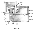
- FIG. 5 is a partial cross-sectional view of the rocker valve mechanism 125 according to an embodiment of the invention.
- the rocker valve mechanism 125 in this embodiment additionally comprises a manual actuation plunger 501 and a manual plunger biasing device 506.
- the manual actuation plunger 501 resides in a bore 500 in the valve body 101 and can move in the bore 500 in a reciprocating manner.
- the bore 500 can include a stop 508 that prevents the manual actuation plunger 501 from escaping the bore 500.
- the manual plunger biasing device 506 resides in the bore 500 and is contacted by the manual actuation plunger 501.
- the manual plunger biasing device 506 returns the manual actuation plunger 501 to a retracted, non-actuated position when there is no actuation force on the manual actuation plunger 501.
- the manual actuation plunger 501 includes an actuator projection 502 that extends from the manual actuation plunger 501.
- the actuator projection 502 includes an angled face 503.
- the actuator projection 502 and the angled face 503 are configured to contact a portion of the rocker valve mechanism 125 and manually force the rocker valve mechanism 125 from a non-actuated position to an actuated position.
- the angled face 503 contacts and depresses a portion of the second plunger 131. In another embodiment, the angled face 503 contacts and depresses a portion of the upper pivot arm 135.
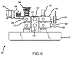
- FIG. 6 is a side view of the rocker valve mechanism 125 according to an embodiment of the invention. This figure shows the manual actuation plunger 501 in a spatial relationship to the rocker valve mechanism 125. In addition, the figure shows a position sensor 160 in a spatial relationship to the rocker valve mechanism 125.
- the position sensor 160 electronically senses the position of the rocker valve mechanism 125 and generates a positional signal.
- the positional signal can be used to determine whether the valve 100 is actuated or non-actuated.
- the positional signal can be used to determine any position of the rocker valve mechanism 125 between the actuated and non-actuated positions.
- the position sensor 160 interacts with a magnet 162 in order to generate the positional signal.
- the magnet 162 is affixed to the rocker valve mechanism 125.
- the magnet 162 is affixed to the upper pivot arm 135 in the embodiment shown in the figure. However, it should be understood that the magnet 162 can be affixed to other structures of the rocker valve mechanism 125, including the lower pivot arm 136 or the first plunger 130, for example.
- FIG. 7 shows an underside of the rocker valve mechanism 125 according to an embodiment of the invention.
- This view shows the first port 113, the second port 114, and the third port 115.
- the first port 113 and the third port 115 comprise elongated slots, while the second port 114 comprises a substantially circular port.
- Corresponding fittings can be accepted by the ports 113-115.
- the rocker valve mechanism 125 can further include a gasket 170 that seals one or more corresponding fittings to the port portion 110. A fitting can compress the gasket 170 in order to form a seal.
- the rocker valve mechanism and rocker valve according to the invention can be employed according to any of the embodiments in order to provide several advantages, if desired.
- the invention provides a rocker valve mechanism wherein sealing portions are displaced substantially parallel to each other.
- the invention provides a rocker valve mechanism that features a reduced displacement span of the rocker biasing device.
- the invention provides a rocker valve mechanism that features an improved rigidity.
- the invention provides a rocker valve mechanism that can be configured to provide a desired actuation force and a desired actuation travel.
- the invention provides a rocker valve mechanism that guarantees contact between a sealing member and a valve seat.
- the invention provides a rocker valve mechanism that features an improved sealing member lifespan.
- the invention provides a rocker valve mechanism that enables configuration of port sizes and port spacings.
- the invention provides a rocker valve mechanism that accommodates various valve seat diameters.
- the invention provides a rocker valve mechanism that provides a reduced internal dead volume and that can be more quickly flushed than in the prior art.
- the invention provides a configurable port portion that can reduce an area of a port interface.
Claims (11)
- Une soupape à culbuteur (100), comprenant :un corps de soupape (101) ; etun mécanisme de soupape à culbuteur (125) situé au moins partiellement à l'intérieur du corps de soupape (101), le mécanisme de soupape à culbuteur (125) comprenant :une portion orifices (110) comportant une pluralité d'orifices (113-115) ;un linguet (133) s'étendant à partir de la portion orifices (110) ;un bras pivot supérieur (135) pivotalement attaché au linguet (133) ;un bras pivot inférieur (136) pivotalement attaché au linguet (133) ;un premier plongeur (130) configuré pour être actionné par un actionneur (145), le premier plongeur (130) étant pivotalement attaché à des premières extrémités (161) du bras pivot supérieur (135) et du bras pivot inférieur (136) ; etun deuxième plongeur (131) pivotalement attaché à des deuxièmes extrémités (162) du bras pivot supérieur (135) et du bras pivot inférieur (136) et agissant en opposition et se déplaçant substantiellement en parallèle avec le premier plongeur (130), le mécanisme de soupape à culbuteur (125) étant incliné vers une première position bloquant un premier orifice (113) et configuré pour être actionné jusqu'à une deuxième position bloquant un troisième orifice (115).
- La soupape à culbuteur (100) de la revendication 1, le mécanisme de soupape à culbuteur (125) comprenant encore un membre joint (120) s'étendant sur le premier plongeur (130) comme sur le deuxième plongeur (131), le membre joint (120) étant déplaçable par le premier plongeur (130) et par le deuxième plongeur (131) pour contacter de façon alternée un premier siège de soupape (112a) du premier orifice (113) et un deuxième siège de soupape (112b) du troisième orifice (115).
- La soupape à culbuteur (100) de la revendication 1, le mécanisme de soupape à culbuteur (125) comprenant un mécanisme de soupape à culbuteur modulaire (125).
- La soupape à culbuteur (100) de la revendication 1, la pluralité d'orifices (113-115) étant séparés par des espacements prédéterminés.
- La soupape à culbuteur (100) de la revendication 1, la pluralité d'orifices (113-115) comprenant une pluralité d'orifices configurables (113-115).
- La soupape à culbuteur (100) de la revendication 2, le premier plongeur (130) comportant une première tête de plongeur (137) et le deuxième plongeur (131) comportant une deuxième tête de plongeur (138), la première tête de plongeur (137) ventant se loger dans une première région d'étanchéité (121) formée dans le membre joint (120) et la deuxième tête de plongeur (138) venant se loger dans une deuxième région d'étanchéité (122) formée dans le membre joint (120).
- La soupape à culbuteur (100) de la revendication 1, le mécanisme de soupape à culbuteur (125) comprenant encore :un dispositif d'inclinaison de culbuteur (140) configuré pour placer une force d'inclinaison sur le deuxième plongeur (131) ; etun actionneur (145) configuré pour faire incliner le premier plongeur (130) et une première région joint du membre joint(120) vers une position normalement fermée et pour le mettre en contact avec un premier siège de valve (112a) du premier orifice (113).
- La soupape à culbuteur (100) de la revendication 7, comprenant encore en plongeur d'actionnement manuel (501) configuré pour transférer une force d'actionnement externe au mécanisme de soupape à culbuteur (125) en opposition avec un dispositif d'inclinaison d'induit (148).
- La soupape à culbuteur (100) de la revendication 7, comprenant encore un plongeur d'actionnement manuel (501) configuré pour transférer une force d'actionnement externe au mécanisme de soupape à culbuteur (125) en opposition avec un dispositif d'inclinaison d'induit (148), le plongeur d'actionnement manuel (501) comportant une saillie actionneuse (502) comportant une face en biais (503).
- La soupape à culbuteur (100) de la revendication 1, comprenant encore un capteur de position (160) qui génère un signal positionnel lié à une position d'actionnement du mécanisme de soupape à culbuteur (125).
- La soupape à culbuteur (100) de la revendication 1, comprenant encore un aimant (162) fixé au mécanisme de soupape à culbuteur (125) et un capteur de position (160) fixé au corps de soupape (101), dans quoi le capteur de position (160) génère un signal positionnel lié à une position d'actionnement du mécanisme de soupape à culbuteur (125).
Applications Claiming Priority (1)
| Application Number | Priority Date | Filing Date | Title |
|---|---|---|---|
| PCT/EP2006/009842 WO2008043381A1 (fr) | 2006-10-12 | 2006-10-12 | Mécanisme de soupape culbutée et soupape culbutée |
Publications (2)
| Publication Number | Publication Date |
|---|---|
| EP2074345A1 EP2074345A1 (fr) | 2009-07-01 |
| EP2074345B1 true EP2074345B1 (fr) | 2011-01-05 |
Family
ID=38197411
Family Applications (1)
| Application Number | Title | Priority Date | Filing Date |
|---|---|---|---|
| EP20060806201 Active EP2074345B1 (fr) | 2006-10-12 | 2006-10-12 | Mécanisme de soupape culbutée et soupape culbutée |
Country Status (7)
| Country | Link |
|---|---|
| US (1) | US8752584B2 (fr) |
| EP (1) | EP2074345B1 (fr) |
| JP (1) | JP5138693B2 (fr) |
| CN (1) | CN101548123B (fr) |
| AT (1) | ATE494502T1 (fr) |
| DE (1) | DE602006019506D1 (fr) |
| WO (1) | WO2008043381A1 (fr) |
Cited By (1)
| Publication number | Priority date | Publication date | Assignee | Title |
|---|---|---|---|---|
| EP3572698A1 (fr) | 2018-05-21 | 2019-11-27 | Fas Medic S.A. | Soupape culbutée comportant un mécanisme de soupape culbutée |
Families Citing this family (22)
| Publication number | Priority date | Publication date | Assignee | Title |
|---|---|---|---|---|
| US8986253B2 (en) | 2008-01-25 | 2015-03-24 | Tandem Diabetes Care, Inc. | Two chamber pumps and related methods |
| US8408421B2 (en) | 2008-09-16 | 2013-04-02 | Tandem Diabetes Care, Inc. | Flow regulating stopcocks and related methods |
| CA2737461A1 (fr) | 2008-09-19 | 2010-03-25 | Tandem Diabetes Care, Inc. | Dispositif de mesure de la concentration d'un solute et procedes associes |
| ES2632954T3 (es) | 2009-06-29 | 2017-09-18 | Agios Pharmaceuticals, Inc. | Derivados de quinolina-8-sulfonamida que tienen una actividad anticancerosa |
| EP2459251B1 (fr) | 2009-07-30 | 2014-03-12 | Tandem Diabetes Care, Inc. | Système de pompe de perfusion à cartouche jetable comprenant une décharge de pression et une rétroaction de pression |
| DE202009016447U1 (de) * | 2009-12-03 | 2010-03-11 | Bürkert Werke GmbH | Fluidisches Steuerelement |
| DE102009058164A1 (de) * | 2009-12-15 | 2011-06-16 | Svm Schultz Verwaltungs-Gmbh & Co. Kg | Ventil mit einem Betätigungsglied |
| US9180242B2 (en) | 2012-05-17 | 2015-11-10 | Tandem Diabetes Care, Inc. | Methods and devices for multiple fluid transfer |
| DE202013100678U1 (de) | 2013-02-14 | 2013-03-05 | Bürkert Werke GmbH | Membranventil |
| US9173998B2 (en) | 2013-03-14 | 2015-11-03 | Tandem Diabetes Care, Inc. | System and method for detecting occlusions in an infusion pump |
| CN105579386B (zh) * | 2013-09-24 | 2018-04-24 | 雀巢产品技术援助有限公司 | 用于饮料分配装置的电磁阀 |
| JP6228439B2 (ja) * | 2013-11-26 | 2017-11-08 | 住友ゴム工業株式会社 | 弁装置 |
| DE102013114595A1 (de) * | 2013-12-20 | 2015-06-25 | Gea Farm Technologies Gmbh | Sicherheitsventil |
| JP6228450B2 (ja) * | 2013-12-24 | 2017-11-08 | 住友ゴム工業株式会社 | 弁装置 |
| US9453437B2 (en) * | 2014-10-29 | 2016-09-27 | Electro-Mechanical Associates, Inc. | Collapsible pushrod valve actuation system for a reciprocating piston machine cylinder |
| CN104676075B (zh) * | 2015-02-12 | 2017-08-11 | 深圳垦拓流体控制有限公司 | 一种改进型电磁阀 |
| CN104676074A (zh) * | 2015-02-12 | 2015-06-03 | 深圳垦拓流体控制有限公司 | 一种直动式电磁阀 |
| DE102019212062A1 (de) * | 2019-08-12 | 2021-02-18 | Festo Se & Co. Kg | Membranventil und Verfahren zur Herstellung eines Membranventils |
| CN212455616U (zh) * | 2020-05-27 | 2021-02-02 | 北京科勒有限公司 | 切换阀 |
| DE102021201140A1 (de) * | 2021-02-08 | 2022-08-11 | Festo Se & Co. Kg | Magnetventil und Verfahren zum Justieren eines Magnetantriebs für ein Magnetventil |
| CN215257991U (zh) | 2021-05-31 | 2021-12-21 | 南昌科勒有限公司 | 切换阀 |
| DE102021208274A1 (de) | 2021-07-30 | 2023-02-02 | Festo Se & Co. Kg | Membranventil |
Family Cites Families (15)
| Publication number | Priority date | Publication date | Assignee | Title |
|---|---|---|---|---|
| GB504172A (en) * | 1938-09-12 | 1939-04-20 | Frederick Howard Stroup | Hand-controlled valve |
| US2935086A (en) * | 1955-04-18 | 1960-05-03 | Samuel K Lehman | Pilot operated valve assembly |
| US3683962A (en) * | 1970-11-19 | 1972-08-15 | Robertshaw Controls Co | Valve construction |
| JPS586101B2 (ja) * | 1978-01-17 | 1983-02-03 | アイシン精機株式会社 | 電磁弁装置 |
| DE3311690C2 (de) * | 1983-03-30 | 1985-05-30 | Heilmeier & Weinlein Fabrik für Oel-Hydraulik GmbH & Co KG, 8000 München | Elektromagnetisch betätigbares Ventil |
| US4569431A (en) * | 1984-05-17 | 1986-02-11 | Terryl K. Qualey | Dual hand control |
| DE3739048C2 (de) | 1987-11-17 | 2001-08-09 | Buerkert Gmbh | Mehrwegeventil |
| CN2033077U (zh) * | 1988-03-05 | 1989-02-22 | 杨玉思 | 液控缓开缓闭止回阀 |
| IT1241327B (it) * | 1990-11-30 | 1994-01-10 | Matrix Srl | Elettrovalvola a tre vie ad alta velocita' per un fluido in pressione, ad esempio per circuiti di aria compressa |
| KR0121813B1 (en) * | 1995-08-18 | 1997-12-08 | Daewoo Electronics Co Ltd | The solenoid valve for a.b.s. |
| CN2345796Y (zh) * | 1998-06-25 | 1999-10-27 | 张家博 | 冷热水混合阀的平衡阀组装装置 |
| US6003552A (en) | 1998-07-13 | 1999-12-21 | Automatic Switch Company | Rocker valve for sealing large orifices |
| US6244296B1 (en) * | 1999-02-23 | 2001-06-12 | Spx Corporation | Position detection for rotary control valves |
| JP4247566B2 (ja) * | 1999-04-14 | 2009-04-02 | Smc株式会社 | バルブ |
| DE20100471U1 (de) * | 2001-01-11 | 2001-03-15 | Buerkert Werke Gmbh & Co | Mikroventil |
-
2006
- 2006-10-12 US US12/443,997 patent/US8752584B2/en active Active
- 2006-10-12 AT AT06806201T patent/ATE494502T1/de not_active IP Right Cessation
- 2006-10-12 JP JP2009531721A patent/JP5138693B2/ja not_active Expired - Fee Related
- 2006-10-12 WO PCT/EP2006/009842 patent/WO2008043381A1/fr active Application Filing
- 2006-10-12 EP EP20060806201 patent/EP2074345B1/fr active Active
- 2006-10-12 CN CN2006800560844A patent/CN101548123B/zh active Active
- 2006-10-12 DE DE200660019506 patent/DE602006019506D1/de active Active
Cited By (2)
| Publication number | Priority date | Publication date | Assignee | Title |
|---|---|---|---|---|
| EP3572698A1 (fr) | 2018-05-21 | 2019-11-27 | Fas Medic S.A. | Soupape culbutée comportant un mécanisme de soupape culbutée |
| US11781670B2 (en) | 2018-05-21 | 2023-10-10 | Fas Medic S.A. | Rocker valve with rocker valve mechanism |
Also Published As
| Publication number | Publication date |
|---|---|
| JP2010506122A (ja) | 2010-02-25 |
| US20100043738A1 (en) | 2010-02-25 |
| WO2008043381A1 (fr) | 2008-04-17 |
| CN101548123B (zh) | 2011-06-08 |
| JP5138693B2 (ja) | 2013-02-06 |
| DE602006019506D1 (de) | 2011-02-17 |
| ATE494502T1 (de) | 2011-01-15 |
| US8752584B2 (en) | 2014-06-17 |
| CN101548123A (zh) | 2009-09-30 |
| EP2074345A1 (fr) | 2009-07-01 |
Similar Documents
| Publication | Publication Date | Title |
|---|---|---|
| EP2074345B1 (fr) | Mécanisme de soupape culbutée et soupape culbutée | |
| KR100637109B1 (ko) | 개선된 밸브 시트가 있는 포핏 밸브 | |
| EP2069667B1 (fr) | Soupape à champignon | |
| EP0703369B1 (fr) | Vanne de commutation piloté | |
| CN110513509B (zh) | 具有摇杆阀机构的摇杆阀 | |
| EP1080323A1 (fr) | Vanne a commande electrique | |
| IE61313B1 (en) | Switching microelectrovalve having a single diaphragm | |
| KR20020050707A (ko) | 포핏식 전자밸브 | |
| CA2469563C (fr) | Soupape pneumatique commandee par pilote | |
| WO2000018382A3 (fr) | Distributeur hydraulique | |
| EP2069660A1 (fr) | Orifice de distributeur à clapet | |
| WO2003104696A1 (fr) | Vanne electromagnetique | |
| KR102128375B1 (ko) | 3방향 전자밸브 | |
| JP2000240835A (ja) | 多方向チェック電磁弁 | |
| CN214425232U (zh) | 一种电磁阀 | |
| JPH0642670A (ja) | チェック弁付3方向流体制御弁 | |
| JPS594213Y2 (ja) | 電磁切換弁 | |
| JP3578652B2 (ja) | ポンプ装置 | |
| JP2889358B2 (ja) | 3方弁のハウジング構造 | |
| JPH0665671U (ja) | 電磁弁 | |
| JP2893426B2 (ja) | 油圧パイロット弁 | |
| AU2002346023A1 (en) | Pilot operated pneumatic valve | |
| EP1800039A1 (fr) | Dispositif pilote electromagnetique, en particulier pour vannes pneumatiques | |
| JP2003278929A (ja) | 方向切換弁 | |
| JPH04290684A (ja) | 電磁弁のプランジャの製造方法 |
Legal Events
| Date | Code | Title | Description |
|---|---|---|---|
| PUAI | Public reference made under article 153(3) epc to a published international application that has entered the european phase |
Free format text: ORIGINAL CODE: 0009012 |
|
| 17P | Request for examination filed |
Effective date: 20090421 |
|
| AK | Designated contracting states |
Kind code of ref document: A1 Designated state(s): AT BE BG CH CY CZ DE DK EE ES FI FR GB GR HU IE IS IT LI LT LU LV MC NL PL PT RO SE SI SK TR |
|
| 17Q | First examination report despatched |
Effective date: 20091102 |
|
| GRAP | Despatch of communication of intention to grant a patent |
Free format text: ORIGINAL CODE: EPIDOSNIGR1 |
|
| GRAS | Grant fee paid |
Free format text: ORIGINAL CODE: EPIDOSNIGR3 |
|
| GRAA | (expected) grant |
Free format text: ORIGINAL CODE: 0009210 |
|
| AK | Designated contracting states |
Kind code of ref document: B1 Designated state(s): AT BE BG CH CY CZ DE DK EE ES FI FR GB GR HU IE IS IT LI LT LU LV MC NL PL PT RO SE SI SK TR |
|
| REG | Reference to a national code |
Ref country code: GB Ref legal event code: FG4D |
|
| REG | Reference to a national code |
Ref country code: CH Ref legal event code: EP |
|
| REG | Reference to a national code |
Ref country code: IE Ref legal event code: FG4D |
|
| REF | Corresponds to: |
Ref document number: 602006019506 Country of ref document: DE Date of ref document: 20110217 Kind code of ref document: P |
|
| REG | Reference to a national code |
Ref country code: DE Ref legal event code: R096 Ref document number: 602006019506 Country of ref document: DE Effective date: 20110217 |
|
| REG | Reference to a national code |
Ref country code: NL Ref legal event code: VDEP Effective date: 20110105 |
|
| PG25 | Lapsed in a contracting state [announced via postgrant information from national office to epo] |
Ref country code: SI Free format text: LAPSE BECAUSE OF FAILURE TO SUBMIT A TRANSLATION OF THE DESCRIPTION OR TO PAY THE FEE WITHIN THE PRESCRIBED TIME-LIMIT Effective date: 20110105 |
|
| REG | Reference to a national code |
Ref country code: CH Ref legal event code: NV Representative=s name: MOINAS & SAVOYE SA |
|
| LTIE | Lt: invalidation of european patent or patent extension |
Effective date: 20110105 |
|
| PG25 | Lapsed in a contracting state [announced via postgrant information from national office to epo] |
Ref country code: ES Free format text: LAPSE BECAUSE OF FAILURE TO SUBMIT A TRANSLATION OF THE DESCRIPTION OR TO PAY THE FEE WITHIN THE PRESCRIBED TIME-LIMIT Effective date: 20110416 Ref country code: SE Free format text: LAPSE BECAUSE OF FAILURE TO SUBMIT A TRANSLATION OF THE DESCRIPTION OR TO PAY THE FEE WITHIN THE PRESCRIBED TIME-LIMIT Effective date: 20110105 Ref country code: GR Free format text: LAPSE BECAUSE OF FAILURE TO SUBMIT A TRANSLATION OF THE DESCRIPTION OR TO PAY THE FEE WITHIN THE PRESCRIBED TIME-LIMIT Effective date: 20110406 Ref country code: LV Free format text: LAPSE BECAUSE OF FAILURE TO SUBMIT A TRANSLATION OF THE DESCRIPTION OR TO PAY THE FEE WITHIN THE PRESCRIBED TIME-LIMIT Effective date: 20110105 Ref country code: IS Free format text: LAPSE BECAUSE OF FAILURE TO SUBMIT A TRANSLATION OF THE DESCRIPTION OR TO PAY THE FEE WITHIN THE PRESCRIBED TIME-LIMIT Effective date: 20110505 Ref country code: LT Free format text: LAPSE BECAUSE OF FAILURE TO SUBMIT A TRANSLATION OF THE DESCRIPTION OR TO PAY THE FEE WITHIN THE PRESCRIBED TIME-LIMIT Effective date: 20110105 Ref country code: PT Free format text: LAPSE BECAUSE OF FAILURE TO SUBMIT A TRANSLATION OF THE DESCRIPTION OR TO PAY THE FEE WITHIN THE PRESCRIBED TIME-LIMIT Effective date: 20110505 |
|
| PG25 | Lapsed in a contracting state [announced via postgrant information from national office to epo] |
Ref country code: FI Free format text: LAPSE BECAUSE OF FAILURE TO SUBMIT A TRANSLATION OF THE DESCRIPTION OR TO PAY THE FEE WITHIN THE PRESCRIBED TIME-LIMIT Effective date: 20110105 Ref country code: NL Free format text: LAPSE BECAUSE OF FAILURE TO SUBMIT A TRANSLATION OF THE DESCRIPTION OR TO PAY THE FEE WITHIN THE PRESCRIBED TIME-LIMIT Effective date: 20110105 Ref country code: PL Free format text: LAPSE BECAUSE OF FAILURE TO SUBMIT A TRANSLATION OF THE DESCRIPTION OR TO PAY THE FEE WITHIN THE PRESCRIBED TIME-LIMIT Effective date: 20110105 Ref country code: BG Free format text: LAPSE BECAUSE OF FAILURE TO SUBMIT A TRANSLATION OF THE DESCRIPTION OR TO PAY THE FEE WITHIN THE PRESCRIBED TIME-LIMIT Effective date: 20110405 Ref country code: CY Free format text: LAPSE BECAUSE OF FAILURE TO SUBMIT A TRANSLATION OF THE DESCRIPTION OR TO PAY THE FEE WITHIN THE PRESCRIBED TIME-LIMIT Effective date: 20110105 Ref country code: BE Free format text: LAPSE BECAUSE OF FAILURE TO SUBMIT A TRANSLATION OF THE DESCRIPTION OR TO PAY THE FEE WITHIN THE PRESCRIBED TIME-LIMIT Effective date: 20110105 Ref country code: AT Free format text: LAPSE BECAUSE OF FAILURE TO SUBMIT A TRANSLATION OF THE DESCRIPTION OR TO PAY THE FEE WITHIN THE PRESCRIBED TIME-LIMIT Effective date: 20110105 |
|
| PG25 | Lapsed in a contracting state [announced via postgrant information from national office to epo] |
Ref country code: EE Free format text: LAPSE BECAUSE OF FAILURE TO SUBMIT A TRANSLATION OF THE DESCRIPTION OR TO PAY THE FEE WITHIN THE PRESCRIBED TIME-LIMIT Effective date: 20110105 Ref country code: DK Free format text: LAPSE BECAUSE OF FAILURE TO SUBMIT A TRANSLATION OF THE DESCRIPTION OR TO PAY THE FEE WITHIN THE PRESCRIBED TIME-LIMIT Effective date: 20110105 |
|
| PLBE | No opposition filed within time limit |
Free format text: ORIGINAL CODE: 0009261 |
|
| STAA | Information on the status of an ep patent application or granted ep patent |
Free format text: STATUS: NO OPPOSITION FILED WITHIN TIME LIMIT |
|
| PG25 | Lapsed in a contracting state [announced via postgrant information from national office to epo] |
Ref country code: RO Free format text: LAPSE BECAUSE OF FAILURE TO SUBMIT A TRANSLATION OF THE DESCRIPTION OR TO PAY THE FEE WITHIN THE PRESCRIBED TIME-LIMIT Effective date: 20110105 Ref country code: CZ Free format text: LAPSE BECAUSE OF FAILURE TO SUBMIT A TRANSLATION OF THE DESCRIPTION OR TO PAY THE FEE WITHIN THE PRESCRIBED TIME-LIMIT Effective date: 20110105 Ref country code: SK Free format text: LAPSE BECAUSE OF FAILURE TO SUBMIT A TRANSLATION OF THE DESCRIPTION OR TO PAY THE FEE WITHIN THE PRESCRIBED TIME-LIMIT Effective date: 20110105 |
|
| 26N | No opposition filed |
Effective date: 20111006 |
|
| REG | Reference to a national code |
Ref country code: DE Ref legal event code: R097 Ref document number: 602006019506 Country of ref document: DE Effective date: 20111006 |
|
| PG25 | Lapsed in a contracting state [announced via postgrant information from national office to epo] |
Ref country code: MC Free format text: LAPSE BECAUSE OF NON-PAYMENT OF DUE FEES Effective date: 20111031 |
|
| REG | Reference to a national code |
Ref country code: IE Ref legal event code: MM4A |
|
| PG25 | Lapsed in a contracting state [announced via postgrant information from national office to epo] |
Ref country code: IE Free format text: LAPSE BECAUSE OF NON-PAYMENT OF DUE FEES Effective date: 20111012 |
|
| PGFP | Annual fee paid to national office [announced via postgrant information from national office to epo] |
Ref country code: IT Payment date: 20121018 Year of fee payment: 7 |
|
| PG25 | Lapsed in a contracting state [announced via postgrant information from national office to epo] |
Ref country code: LU Free format text: LAPSE BECAUSE OF NON-PAYMENT OF DUE FEES Effective date: 20111012 |
|
| PG25 | Lapsed in a contracting state [announced via postgrant information from national office to epo] |
Ref country code: TR Free format text: LAPSE BECAUSE OF FAILURE TO SUBMIT A TRANSLATION OF THE DESCRIPTION OR TO PAY THE FEE WITHIN THE PRESCRIBED TIME-LIMIT Effective date: 20110105 |
|
| PG25 | Lapsed in a contracting state [announced via postgrant information from national office to epo] |
Ref country code: HU Free format text: LAPSE BECAUSE OF FAILURE TO SUBMIT A TRANSLATION OF THE DESCRIPTION OR TO PAY THE FEE WITHIN THE PRESCRIBED TIME-LIMIT Effective date: 20110105 |
|
| PGFP | Annual fee paid to national office [announced via postgrant information from national office to epo] |
Ref country code: CH Payment date: 20131014 Year of fee payment: 8 |
|
| PG25 | Lapsed in a contracting state [announced via postgrant information from national office to epo] |
Ref country code: IT Free format text: LAPSE BECAUSE OF NON-PAYMENT OF DUE FEES Effective date: 20131012 |
|
| REG | Reference to a national code |
Ref country code: CH Ref legal event code: PL |
|
| PG25 | Lapsed in a contracting state [announced via postgrant information from national office to epo] |
Ref country code: LI Free format text: LAPSE BECAUSE OF NON-PAYMENT OF DUE FEES Effective date: 20141031 Ref country code: CH Free format text: LAPSE BECAUSE OF NON-PAYMENT OF DUE FEES Effective date: 20141031 |
|
| REG | Reference to a national code |
Ref country code: FR Ref legal event code: PLFP Year of fee payment: 11 |
|
| REG | Reference to a national code |
Ref country code: FR Ref legal event code: PLFP Year of fee payment: 12 |
|
| REG | Reference to a national code |
Ref country code: FR Ref legal event code: PLFP Year of fee payment: 13 |
|
| REG | Reference to a national code |
Ref country code: DE Ref legal event code: R082 Ref document number: 602006019506 Country of ref document: DE Representative=s name: CABINET BEAUMONT, FR Ref country code: DE Ref legal event code: R081 Ref document number: 602006019506 Country of ref document: DE Owner name: FAS MEDIC S.A., CH Free format text: FORMER OWNER: FLUID AUTOMATION SYSTEMS S.A., VERSOIX, CH Ref country code: DE Ref legal event code: R082 Ref document number: 602006019506 Country of ref document: DE Representative=s name: WITHERS & ROGERS LLP, DE |
|
| REG | Reference to a national code |
Ref country code: GB Ref legal event code: 732E Free format text: REGISTERED BETWEEN 20200220 AND 20200226 |
|
| REG | Reference to a national code |
Ref country code: DE Ref legal event code: R082 Ref document number: 602006019506 Country of ref document: DE Representative=s name: CABINET BEAUMONT, FR Ref country code: DE Ref legal event code: R082 Ref document number: 602006019506 Country of ref document: DE Representative=s name: WITHERS & ROGERS LLP, DE |
|
| REG | Reference to a national code |
Ref country code: DE Ref legal event code: R082 Ref document number: 602006019506 Country of ref document: DE Representative=s name: WITHERS & ROGERS LLP, DE |
|
| PGFP | Annual fee paid to national office [announced via postgrant information from national office to epo] |
Ref country code: GB Payment date: 20231013 Year of fee payment: 18 |
|
| PGFP | Annual fee paid to national office [announced via postgrant information from national office to epo] |
Ref country code: FR Payment date: 20231024 Year of fee payment: 18 Ref country code: DE Payment date: 20231020 Year of fee payment: 18 |
|
| P01 | Opt-out of the competence of the unified patent court (upc) registered |
Effective date: 20240301 |