EP2074024B1 - Freitragende innenkabinenstruktur mit integrierten einbauelementen und verfahren zur installation - Google Patents
Freitragende innenkabinenstruktur mit integrierten einbauelementen und verfahren zur installation Download PDFInfo
- Publication number
- EP2074024B1 EP2074024B1 EP07818918A EP07818918A EP2074024B1 EP 2074024 B1 EP2074024 B1 EP 2074024B1 EP 07818918 A EP07818918 A EP 07818918A EP 07818918 A EP07818918 A EP 07818918A EP 2074024 B1 EP2074024 B1 EP 2074024B1
- Authority
- EP
- European Patent Office
- Prior art keywords
- cabin
- structural unit
- cabin structural
- aircraft
- elements
- Prior art date
- Legal status (The legal status is an assumption and is not a legal conclusion. Google has not performed a legal analysis and makes no representation as to the accuracy of the status listed.)
- Not-in-force
Links
- 238000009434 installation Methods 0.000 title claims abstract description 118
- 238000000034 method Methods 0.000 title claims abstract description 30
- 238000013016 damping Methods 0.000 claims description 7
- 230000010355 oscillation Effects 0.000 claims description 7
- 230000003014 reinforcing effect Effects 0.000 abstract 2
- 238000004519 manufacturing process Methods 0.000 description 12
- 238000012423 maintenance Methods 0.000 description 7
- 230000003068 static effect Effects 0.000 description 7
- 239000000463 material Substances 0.000 description 6
- 230000009467 reduction Effects 0.000 description 6
- 239000002131 composite material Substances 0.000 description 5
- 230000009975 flexible effect Effects 0.000 description 4
- 230000002787 reinforcement Effects 0.000 description 4
- 238000005452 bending Methods 0.000 description 3
- 230000008859 change Effects 0.000 description 3
- 238000010276 construction Methods 0.000 description 3
- 238000006073 displacement reaction Methods 0.000 description 3
- 238000009420 retrofitting Methods 0.000 description 3
- 238000007789 sealing Methods 0.000 description 3
- 230000007704 transition Effects 0.000 description 3
- 230000008901 benefit Effects 0.000 description 2
- 230000002950 deficient Effects 0.000 description 2
- 230000000694 effects Effects 0.000 description 2
- 229920001296 polysiloxane Polymers 0.000 description 2
- 230000008569 process Effects 0.000 description 2
- 238000000926 separation method Methods 0.000 description 2
- 229920001875 Ebonite Polymers 0.000 description 1
- 239000000853 adhesive Substances 0.000 description 1
- 230000001070 adhesive effect Effects 0.000 description 1
- 150000001875 compounds Chemical class 0.000 description 1
- 239000004035 construction material Substances 0.000 description 1
- 239000011162 core material Substances 0.000 description 1
- 238000005516 engineering process Methods 0.000 description 1
- 239000002657 fibrous material Substances 0.000 description 1
- 230000004907 flux Effects 0.000 description 1
- 230000005484 gravity Effects 0.000 description 1
- 239000012774 insulation material Substances 0.000 description 1
- 238000002955 isolation Methods 0.000 description 1
- 230000035515 penetration Effects 0.000 description 1
- 230000000717 retained effect Effects 0.000 description 1
- 230000035939 shock Effects 0.000 description 1
- 238000009423 ventilation Methods 0.000 description 1
Images


Classifications
-
- B—PERFORMING OPERATIONS; TRANSPORTING
- B64—AIRCRAFT; AVIATION; COSMONAUTICS
- B64C—AEROPLANES; HELICOPTERS
- B64C1/00—Fuselages; Constructional features common to fuselages, wings, stabilising surfaces or the like
- B64C1/06—Frames; Stringers; Longerons ; Fuselage sections
- B64C1/068—Fuselage sections
-
- B—PERFORMING OPERATIONS; TRANSPORTING
- B64—AIRCRAFT; AVIATION; COSMONAUTICS
- B64C—AEROPLANES; HELICOPTERS
- B64C1/00—Fuselages; Constructional features common to fuselages, wings, stabilising surfaces or the like
- B64C1/06—Frames; Stringers; Longerons ; Fuselage sections
-
- B—PERFORMING OPERATIONS; TRANSPORTING
- B64—AIRCRAFT; AVIATION; COSMONAUTICS
- B64C—AEROPLANES; HELICOPTERS
- B64C1/00—Fuselages; Constructional features common to fuselages, wings, stabilising surfaces or the like
- B64C1/06—Frames; Stringers; Longerons ; Fuselage sections
- B64C1/066—Interior liners
-
- B—PERFORMING OPERATIONS; TRANSPORTING
- B64—AIRCRAFT; AVIATION; COSMONAUTICS
- B64C—AEROPLANES; HELICOPTERS
- B64C2211/00—Modular constructions of airplanes or helicopters
-
- B—PERFORMING OPERATIONS; TRANSPORTING
- B64—AIRCRAFT; AVIATION; COSMONAUTICS
- B64D—EQUIPMENT FOR FITTING IN OR TO AIRCRAFT; FLIGHT SUITS; PARACHUTES; ARRANGEMENTS OR MOUNTING OF POWER PLANTS OR PROPULSION TRANSMISSIONS IN AIRCRAFT
- B64D11/00—Passenger or crew accommodation; Flight-deck installations not otherwise provided for
- B64D2011/0046—Modular or preassembled units for creating cabin interior structures
-
- Y—GENERAL TAGGING OF NEW TECHNOLOGICAL DEVELOPMENTS; GENERAL TAGGING OF CROSS-SECTIONAL TECHNOLOGIES SPANNING OVER SEVERAL SECTIONS OF THE IPC; TECHNICAL SUBJECTS COVERED BY FORMER USPC CROSS-REFERENCE ART COLLECTIONS [XRACs] AND DIGESTS
- Y02—TECHNOLOGIES OR APPLICATIONS FOR MITIGATION OR ADAPTATION AGAINST CLIMATE CHANGE
- Y02T—CLIMATE CHANGE MITIGATION TECHNOLOGIES RELATED TO TRANSPORTATION
- Y02T50/00—Aeronautics or air transport
- Y02T50/40—Weight reduction
-
- Y—GENERAL TAGGING OF NEW TECHNOLOGICAL DEVELOPMENTS; GENERAL TAGGING OF CROSS-SECTIONAL TECHNOLOGIES SPANNING OVER SEVERAL SECTIONS OF THE IPC; TECHNICAL SUBJECTS COVERED BY FORMER USPC CROSS-REFERENCE ART COLLECTIONS [XRACs] AND DIGESTS
- Y10—TECHNICAL SUBJECTS COVERED BY FORMER USPC
- Y10T—TECHNICAL SUBJECTS COVERED BY FORMER US CLASSIFICATION
- Y10T29/00—Metal working
- Y10T29/49—Method of mechanical manufacture
- Y10T29/49826—Assembling or joining
Definitions
- the present invention relates to a cabin structural unit for attaching cabin installation elements for an aircraft, a method for attaching cabin installation elements for an aircraft, a use of a cabin structural unit for attaching cabin installation elements, a method for installing a cabin structural unit, and an aircraft comprising a cabin structural unit for attaching cabin installation elements.
- the cabin installation elements such as baggage compartments, panel parts, or other internal installation elements are installed directly to the aircraft structure, such as the frames, the stringers, or other supporting elements of the aircraft fuselage.
- the aircraft structure is continuously subjected to deformations. This deformation of the aircraft structure thus automatically also results in a change of the position of the cabin installation elements, because they are attached directly to the structure.
- gaps having a sufficient width run between the cabin installation elements.
- the gaps may have dimensions between 8 mm and 25.4 mm, for example.
- the cabin installation elements may move in relation to one another without wedging or other damage of the cabin installation elements occurring upon a deformation of the aircraft structure.
- these gaps must be appropriately sealed to prevent or to minimize a temperature exchange or a noise exchange between the internal cabin and the environment. Therefore, the radial gap is sealed using a so-called infill strip and the remaining gaps are typically sealed using a silicone lip seal.
- US 4,799,631 which is considered the closest prior art, describes a module for the interior of an aircraft fuselage containing a fuselage deck, wherein the module comprises contiguous pairs of arcuate port and starboard panels having a first end. The first end of each panel is mounted in multiple isolaters located within separate overhead support channels.
- the object may be achieved by a cabin structural unit, as defined by the features of claim 1, for attaching cabin installation elements and a method for attaching cabin installation elements for an aircraft and by the use of a cabin structural unit for attaching cabin installation elements in an aircraft, by a method for installing a cabin structural unit, and an aircraft having a cabin structural unit for attaching cabin installation elements having the features according to the independent claims.
- a cabin structural unit for attaching cabin installation elements for an aircraft is provided.
- the cabin structural unit is set up in such a way that a cabin installation element is attachable.
- the cabin structural unit is adapted for being self-supporting. Furthermore, the cabin structural unit adapted for being fastenable to an aircraft structure.
- a cabin system for attaching cabin installation elements comprises a first cabin structural unit described above and a second cabin structural unit described above as well as a compensation element.
- the compensation element is set up between the first cabin structural unit and the second cabin structural unit in such a way that tolerances may be compensated for.
- the compensation element may also consist of door entrance sections or galleys that are able to compensate movements between the different cabin structural units.
- a method for attaching cabin installation elements for an aircraft is provided, as defined by the features of claim 10.
- a cabin installation element is fastened to a cabin structural unit.
- the cabin structural unit is fastened to an aircraft structure, the cabin structural unit being implemented as self-supporting.
- a cabin structural unit for attaching cabin installation elements is used in an aircraft, as defined by the features of claim 11.
- an aircraft having a cabin structural unit for attaching cabin installation elements according to one of the above embodiments is provided, as defined by the features of claim 12.
- self-supporting is understood as a component and/or a structural unit which manages to fulfill its function even without further load-carrying elements.
- the "self-supporting" structural unit is to be implemented in such a way that all stresses occurring in operation may be absorbed by the structural unit.
- a self-supporting structural unit may absorb forces and torques without having to be supported itself by other external structures.
- a statically stable, freestanding structure is thus understood as a "self-supporting structure”.
- the self-supporting cabin structural unit may thus retain the cabin installation elements independently self-supporting, without being depended on support functions of the aircraft structure. Therefore, struts and reinforcements between the cabin structural unit and the aircraft structure may be dispensed with. Because of the few contact points of the cabin structure with the aircraft structure, the deformations of the aircraft fuselage and/or the aircraft structure are hardly relayed to the cabin structural unit, so that a relative movement of the cabin installation elements to one another is reduced.
- the cabin structural unit thus forms a unit that is statically independent per se, without structural reinforcement measures connected to the aircraft structure being needed.
- the cabin structural unit may only be secured in regard to displacement within the aircraft structure. Other torques, stresses, or strains may not or hardly introduced from the aircraft structure into the self-supporting cabin structure.
- the cabin structural unit may thus be independent of a deformation of the aircraft structure.
- the construction of the cabin structural unit may be understood as that of a tent, in which an internal tent and an external tent exist independently of one another, the internal tent solely having to be secured against slipping from the external tent. Movements of the external tent hardly influence the internal tent.
- the effects of wind, temperature, or other structural movements on the cabin structure are thus damped and only transmitted via the fasteners between the cabin structural unit and the aircraft structure, so that a deformation of the cabin structural unit and thus the cabin installation elements may hardly occur.
- the cabin structural unit thus forms a united self-supporting and/or freestanding static composite with the cabin installation elements, without or respectively almost without absorbing deformation torques of the external aircraft structure.
- the required compensation gaps may be greatly reduced in their width, because hardly any relative movement exists between the cabin installation elements due to the cabin structure. Therefore, wide tolerance gaps may no longer necessary.
- the cabin installation elements may thus be situated in such a way that only small separation gaps remain. These separation gaps may be implemented as joins by introducing a silicone sealing compound, for example. Because of the reduction of the width of the gaps between the cabin installation elements, a higher state of comfort, design, and noise level may be achieved. In addition, the number of lip seals may be reduced. Because of the reduction of the size of the gaps, a lower noise level enters the cabin.
- aircraft structure may understood as all supporting elements of an aircraft, such as stringers, frames, transverse girders, floor girders, or other supporting elements of an aircraft fuselage.
- a compensation element may be understood as a gap as well as damper elements that may compensate for a movement of the first cabin structural unit and the second cabin structural unit to one another.
- Tolerances mean, for example, movement tolerance, dimensional tolerances, or strain tolerances, which are induced because of temperature changes, for example.
- the cabin structural unit comprises a loose bearing device.
- the cabin structural unit may be fastened to an aircraft structure using the loose bearing device in such a way that the cabin structural unit is displaceable along an aircraft longitudinal direction.
- the term loose bearing device is understood as a freely movable bearing which comprises at least one degree of translation freedom, i.e., permits movements in one direction
- aircraft longitudinal direction is understood as the direction in which the fuselage extends cylindrically.
- an aircraft-fixed coordinate system in which the x-axis extends along this aircraft longitudinal direction, i.e., is defined along the extension direction of the aircraft fuselage.
- the lateral extension direction i.e., orthogonal to the x direction, is called the y-axis.
- the extension in the vertical orientation and orthogonal to the x and y axes is called the z-axis.
- the cabin structural unit may be movable and/or displaced in relation to the aircraft structure.
- the cabin structural unit including the cabin installation elements fastened thereto may be displaced along the aircraft longitudinal direction, i.e., along the x-axis. Because of the loose bearing device, no deformation forces of the aircraft structure are thus transmitted to the cabin structural unit.
- the cabin layout may be changed flexibly using the cabin structural unit, because the cabin installation elements, such as entire rows of seats including their associated baggage compartments, may be fastened to a cabin structural unit and thus are displaceable easily and rapidly as a whole. Large amounts of retrofitting work may not necessary for this purpose, so that the retrofitting time and the retrofitting costs of a cabin layout may be reduced.
- the cabin structural unit comprises a fixed bearing device.
- the cabin structural unit may be fastenable to the aircraft structure using the fixed bearing device in such a way that forces are transmittable along the aircraft longitudinal axis.
- a fixed bearing device is understood as a bearing apparatus, which fixes the cabin structural unit in all three degrees of translation freedom. Torques, such as bending torques, torsion torques, or other torques, which are induced by the aircraft structure, may not be transmitted using the fixed bearing, so that nonetheless no deformation of the cabin structure occurs. At the fixed bearings, the forces are transmitted punctual, for example.
- the cabin structural units may be partially decoupled, so that deformations of the cabin structural units as result of deformation of the fuselage may be reduced.
- the cabin installation structure may be secured against displacements in relation to the aircraft structure, without deformation torques being transmitted from the aircraft structure to the cabin structural unit. Therefore, in spite of deformation of the aircraft structure, the cabin structural unit remains dimensionally stable, i.e., deformation energy and/or deformation torques are not transmitted respectively deformation energy and deformation torques are transmitted only marginally. Therefore, the cabin structural unit may be fastened to the aircraft structure in relation to the aircraft longitudinal direction, without forces, which are caused because of external influencing factors, such as temperature differences or other structural movements, being transmitted to the cabin structural unit. Therefore, the size and/or the width of the compensation gaps that are situated between the cabin installation elements to buffer relative movements may be reduced.
- the cabin structural unit comprises a damping element.
- the cabin structural unit may be fastenable to the aircraft structure using the damping element in such a way that oscillations of the aircraft structure may be damped. Oscillations of the aircraft structure arise, for example, due to the aircraft engine or due to natural oscillations of the components.
- the oscillations may be reduced between the connection points of the self-supporting cabin structure and the aircraft structure using the damping elements, by which the influence of the oscillations on the cabin installation elements is also reduced.
- Damping elements may comprise hard rubber, the so-called shock mounts, or spring-damper systems, for example.
- the cabin structural unit comprises a plurality of support frames and a longitudinal stiffening rib, the longitudinal stiffening ribs being set up between each of the plurality of support frames.
- the longitudinal stiffening rib is set up to transmit a force along the aircraft longitudinal axis or the x-axis.
- a longitudinal stiffening rib is inserted between each two support frames to transmit forces along the aircraft longitudinal axis. Therefore, a static, stable composite of support frames and longitudinal stiffening ribs may be provided, which may comprise low material requirements.
- a static, stable, and self-supporting cabin structural unit may be provided using this light construction, to which arbitrarily many cabin installation elements may be attachable.
- the longitudinal stiffening rib may consist of a rip or a ventilation duct, for instance.
- the cabin structural unit also comprises a fastener, the cabin installation elements being replaceably fastenable to the cabin structural unit using the fastener.
- the fastener may comprise various quick-release fasteners, screw connections, or other removable fasteners to fasten the cabin installation element to the cabin structural unit.
- plug-in systems may also be used as fasteners, which rapidly connect the cabin installation elements of the cabin structure. Therefore, the cabin installation elements, such as a baggage compartment or an aircraft seat, may be removed from the cabin structural unit using a few handles and replaced by other cabin installation elements. For example, if a seat element is defective, it may be replaced rapidly by an intact seat element, without arising long maintenance times and thus maintenance costs.
- the cabin installation element may be installed integrally and in one piece to the cabin structural unit.
- a baggage compartment may be manufactured together with a support frame and installed in the cabin. Therefore, entire units may be installed more rapidly in aircraft structure and may additionally be manufactured with less material outlay. If a cabin installation element is integral and in one piece, i.e., a part of the cabin structural unit, fasteners or tolerances may be dispensed with.
- the cabin installation element is set up on the cabin structural unit in such a way that a force flux is transmittable. Therefore, the cabin installation element itself may reinforce the static composite of the cabin structural unit.
- the cabin installation element is connected to the cabin structural unit in such a way that forces are transmittable in all translation directions. Further reinforcement elements which have to contribute to the self-supporting cabin structural unit may thus become unnecessary and/or be reduced. Therefore, material and costs may be saved.
- the cabin structural unit comprises a stiffening face.
- the cabin structural unit may thus be manufactured in shell form, the shell comprising composite fiber material, for example. Therefore, the static composite of the cabin structural unit may comprise a semicircular shape along the aircraft longitudinal axis, for example, which may absorb all forces of the cabin installation elements.
- the stiffening faces may simultaneously represent a cabin panel, so that no further design elements are additionally necessary.
- a sandwich construction comprising a core material, such as a so-called honeycomb having prepreg layers, may be used as a construction material for the stiffening faces.
- the honeycomb comprises a honeycomb structure. Weight and costs may be saved by these stiffening faces.
- the support frames of the plurality of support frames comprise a plurality support elements, the plurality of support elements being removably fastenable to one another.
- the support frames may be constructed modularly using removable fasteners, such as screw connections, and may be changed in their size, for example. This may offer advantages when mounting the support frames, adaptability to various fuselage diameters being.made possible. Multiple standard parts may be used precisely in consideration of production technologies, which may be adjusted in their overall size using individually manufactured parts of different sizes. Production costs and mounting costs may thus be reduced.
- the plurality of support elements are fastenable to one another using a plug-in connection.
- a cabin structure may be assembled rapidly using a plug-in connection, without having to use fasteners.
- the aircraft structure comprises a floor structure, the cabin structural unit being fastenable to the floor structure.
- the floor structure of an aircraft runs transversely in the horizontal direction to the aircraft longitudinal axis. No respectively less external effects, which normally engage on the aircraft skin, engage on the floor structure and/or the transverse girders of the aircraft structure. Therefore, external influences which are induced by wind or ambient temperatures may be neglected.
- the floor structure thus comprises less deformation than the aircraft skin and/or the stringers and frames of the aircraft skin. Therefore, a deformation of the fastening face of the cabin structural unit may be reduced and/or damped.
- the cabin installation unit is selected from the group comprising toilet units, kitchen units, seat units, design elements, stairway elements, baggage compartments, air provision units, window panels, and elevator units.
- toilet units kitchen units, seat units, design elements, stairway elements, baggage compartments, air provision units, window panels, and elevator units.
- the cabin structural unit comprises cabin structural segments, wherein the cabin structural segments are connected by hinges for being foldable.
- Each cabin structural unit is divided in a plurality of cabin structural segments.
- the cabin structural segments may consist of the longitudinal stiffening rips, stiffening faces, air ducts or any other segments that provides static properties for the cabin structural units.
- the entirety of the cabin structural segments may form the cabin structural unit in circumferential direction for example.
- the volume of the whole unit may be reduced, so that the mounting of the unit may be eased.
- the cabin structural unit may be folded together and carried to the mounting position and thus be extracted to the operational design. It is also possible to preassemble the cabin structural unit with its cabin installation elements outside of the aircraft fuselage and then carrying the preassembled and folded cabin structural unit into the aircraft fuselage to the mounting position.
- the preassembled and folded cabin structural unit may be carried through small openings, such as doors of an aircraft, so that it is also easier to change the cabin layout after the fuselage is assembled together.
- the cabin structural unit further comprises interface elements.
- the interface elements are adapted to connect the cabin installation elements with the aircraft structure or with the floor structure.
- interface elements may be provided for achieving an easy and short time assembling procedure. If the cabin installation element consists for instance of a window, the window has to be connected to the window opening in the aircraft structure.
- an interface element has to be provided in order to seal the inside of the aircraft from the low-pressure environment.
- the interface elements may consist of an easy push-in and snap connection comprising window-sealing elements etc..
- the interface elements may also provide compensation properties in order to compensate relative movements between the cabin structural unit and the fuselage structure as a result of different temperature or pressure levels, for instance.
- the interface elements may also be selected from one of the group consisting of electrical connectors, air duct connectors or data line connectors.
- the cabin structural unit is adapted for supporting the aircraft structure.
- the cabin structural unit is self-supporting, so that the cabin structural unit may hold its own weight.
- the cabin structural unit may be adapted for absorbing forces and torques for example from the fuselage structure.
- the aircraft structure may be designed more lightweight so that the overall weight of the aircraft may be reduced.
- the cabin structural unit may thus comprise static properties in order to support the aircraft structure.
- the cabin element in a first step, is attached to the cabin structural unit and in a following second step, the cabin structural unit inclusively the cabin installation element is fastened to the aircraft structure.
- the aircraft mounting may be performed in simultaneously to the cabin mounting and not, as is typical, the aircraft being produced first and the cabin then being mounted. This results in reduced production times and thus lower production costs.
- the cabin structural unit is thus pre-mountable as a whole or only partially including all cabin installation elements and may subsequently be introduced into the aircraft fuselage.
- the sections of the aircraft fuselage remain open during the mounting of the cabin structure and are closed using the aircraft tail or aircraft bow after the cabin mounting.
- a method for installing a cabin structural unit for an aircraft as described above is provided, as defined by the features of claim 13.
- the cabin structural unit is pre-assembled outside of an aircraft structure.
- the pre-assembled cabin structural unit is guided through an opening of the aircraft structure. Further on, the pre-assembled cabin structural unit is implemented at a predetermined location in the aircraft structure.
- the pre-assembled cabin structural unit is fixed at the predetermined location in the aircraft structure.
- the installing method it is possible to preassemble the cabin structural unit outside of an aircraft so that assembling proceedings of the aircraft may be separated and accomplished simultaneously.
- the isolation of the aircraft structure may be installed, whereas the cabin structural units may be assembled outside of the aircraft simultaneously.
- the whole cabin structural units may be guided to the open fuselage sections and then installed at a predetermined location in the aircraft structure.
- the logistic complexity may be reduced, because all equipment parts, such as cabin installation elements may be stored and assembled outside of the aircraft fuselage.
- the amount of assemblers working in the fuselage simultaneously may be reduced, because the assemblers for the cabin structural unit may assemble the cabin outside of the aircraft fuselage.
- the assembling procedures are more economically and ergonomically because more space for the assemblers may be available.
- the assembling procedures of the fuselage, the cabin and the whole aircraft may be eased and accomplished more quickly.
- the pre-assembled cabin structural unit is adapted to be foldable.
- the pre-assembled cabin structural unit is folded before guiding the pre-assembled cabin structural unit through the opening of the aircraft structure.
- the pre-assembled cabin structural unit is unfolded.
- cabin structural units By folding the cabin structural units, respectively the preassembled cabin structural units, less space respectively smaller openings in the aircraft fuselage have to be provided in order to guide the cabin structural unit into the fuselage to the predetermined fixing points.
- the cabin structural units In the aircraft fuselage the cabin structural units may be unfolded and fixed to the predetermined location.
- small openings such as doors, are capable for guiding the folded preassembled cabin structural unit into the fuselage.
- cabin structural units may be assembled also exchangeable. If, for instance, the airliners prefer flexible cabin layouts, changes in the cabin layout may be provided quickly by folding the cabin structural units, guiding them outside of the aircraft fuselage through the door and installing another different cabin structural unit.
- the cabin installation element is installed into the pre-assembled cabin structural unit outside of the aircraft structure.
- the cabin installation elements may be assembled to the cabin structural unit simultaneously to the aircraft structure. The overall production time may be reduced.
- the opening of the aircraft structure is selected from one of the group consisting of fuselage doors, openings of fuselages segments and cargo doors.
- the cabin structural unit comprises cabin structural segments, wherein the cabin structural segments are connected by hinges for being foldable.
- the cabin structural unit may also be divided into cabin structural segments that are connected by hinges, so that several possibilities of folding a cabin structural unit may be provided.
- a very small volume of a folded and preassembled cabin structural unit may be provided, so that even the smallest openings in the fuselage structure may be utilized for guiding this cabin structural unit to the predetermined assembling location into the fuselage.
- the exemplary aspects of the cabin structural unit also relate to the cabin system, the method, the use, the aircraft and the method for installing a cabin structural unit, and vice versa.
- Fig. 3 shows an exemplary aspect of the present invention, in which a cabin structural unit 1 having cabin installation elements 2 is shown in an aircraft structure 5.
- the cabin structural unit 1 is provided for attaching cabin installation elements 2 for an aircraft.
- the cabin structural unit 1 is adapted for attaching a cabin installation unit 2.
- the cabin structural unit 1 is adapted for being self-supporting and fastenable to an aircraft structure 5, 6.
- the cabin structural unit 1 may be attached using a loose bearing 3 or a fixed bearing 4 to an aircraft structure 5 or a floor structure 6 of the aircraft. Because the cabin structural unit 1 is implemented as self-supporting, no additional stiffening means or fasteners may be attached to the aircraft structure 5 or the floor structure 6.
- this cabin structural unit 1 may be manufactured outside the aircraft structure 5 and equipped with the cabin installation elements 2, for example. Then may the cabin structural unit 1 be installed as a whole in the aircraft structure 5. Therefore, parallel manufacturing sequences, on one hand, for example, manufacturing the aircraft fuselage, and on the other hand simultaneously manufacturing the cabin structural unit 1, may be implemented, so that production costs may be saved.
- Fig. 1 shows an exemplary aspect of a configuration of cabin installation elements 2, as it is known from the prior art.
- the cabin installation elements 2 are fastened individually to the aircraft structure 5. Because of deformations of the aircraft structure 5, for example, as a result of external influences such as temperature oscillations or flight strains, either a radial gap 13 or a longitudinal gap 14 has to be provided between each cabin installation element 2. Only in this way may relative movements between the cabin installation elements 2 be compensated for.
- the radial gaps 13 and the longitudinal gaps 14 may, however, dampen or insulate noise or temperature only poorly or not at all. Therefore, noise and ambient temperature enters the cabin interior through the gaps 13, 14, which may result in a disadvantage in cabin comfort.
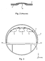
- Fig. 2 shows a seal configuration of the radial gaps 13 and the longitudinal gaps 14 known from the prior art.
- a seal such as a lip seal 15
- These lip seals 15 are subject to maintenance, however, and therefore have to be monitored for their tightness and maintained continuously, so that a high maintenance effort and high material costs arise.
- a replacement of cabin elements 2 results in the lip seals 15 additionally having to be replaced, because of which additional material costs may arise.
- Fig. 4 shows a spatial illustration of a further exemplary aspect of the cabin structural unit 1.
- Various cabin installation elements 2 may be situated independently of an aircraft structure 5 on the cabin structural unit 1.
- the cabin installation elements 2 may comprise baggage stowing spaces, the so-called hatracks, or other panel or seat elements, as shown.
- the cabin structural unit I may comprise a plurality of support frames 11 and/or stiffening faces 9.
- the cabin structure 1, which comprises stiffening faces 9 and/or support frames 11, is implemented as self-supporting, so that no support connections are needed between the aircraft structure 5 and the cabin structural unit 1.
- the cabin structure 1 may, for example, be situated using a loose bearing 3 or a fixed bearing 4 on the aircraft structure 5 or, as shown in Fig. 4 , for example, on the floor structure 6.
- the cabin structural unit 1 may be retained in its position in relation to the aircraft fuselage and/or the aircraft structure 5, without torques of the aircraft structure 5 being transmitted to the cabin structural unit 1.
- torques may comprise torsion torques or bending torques of the fuselage, for example.
- the deformation torques i.e., the bending or torsion torques of the aircraft structure, for example, are no longer transmitted to the cabin structural unit 1, on which the cabin installation elements 2 are situated, no or hardly any relative movement of the cabin installation elements 2 occurs. Therefore, no compensation gaps, i.e., radial gaps 13 or longitudinal gaps 14, have to be provided between the cabin elements 2. Insulation material, such as lip seals 15, may be saved by the reduction of the gaps 13, 14 and greater tightness to noise and external temperature influences may additionally be provided.
- Fig. 5 shows an enlarged view of a cabin structural unit 1, to which installation elements 2 are attached.
- the cabin structural unit 1 comprises curved support frames 11, which additionally have reinforcement faces 9.
- Longitudinal stiffening ribs are additionally situated for stiffening in the cabin structural unit 1 along the aircraft longitudinal axis and/or along the x-axis of an aircraft-fixed coordinate system. Therefore, a self-supporting cabin structural unit 1 may be provided, which may support and/or absorb the loads of the cabin installation elements 2.
- Other cabin installation elements 2, such as supply lines 7, may also be situated on the cabin structural unit 1. Therefore, the possibility additionally exists of situating any lines for the electronics or air delivery lines of the air conditioner or other supply lines 7 on the cabin structural unit.
- connection pipes 7 may also be dispensed with, and/or the manufacturing tolerances of the connection pipes 7 may be reduced.
- the cabin installation elements 2 may be fastened to the cabin structural unit 1 using removable fasteners, so that a rapid replacement may be performed.
- any cabin installation unit 2 may be removably attached to the cabin structural unit 1, so that a rapid exchange of the entire cabin layout may be performed.
- Complex and costly seal elements, such as lip seals between the cabin elements 2 may be dispensed with, because no gap 13, 14 exists.
- Fig. 6 shows an exemplary aspect of a cabin structural unit 1.
- the cabin structural unit 1 comprises various support frames 11, which comprise a plurality of support elements 12.
- the cabin structural unit 1 comprises longitudinal stiffening ribs 8 and stiffening faces 9.
- the support elements 12, the stiffening faces 9, and the longitudinal stiffening ribs 8 may be assembled via a plug-in connection in a simple way, for example, all necessary forces being able to be transmitted.
- a simple system may be provided, which allows flexible and rapid replacement of support elements 12 or stiffening faces 9 or longitudinal stiffening ribs 8.
- different sized elements of the cabin structural unit 1 may be used to adjust the size of the cabin structural unit 1.
- FIG. 6 An exemplary aspect of a loose bearing 3 is additionally shown in Fig. 6 .
- the cabin structural unit 1 may be mounted via a rail system, for example.
- the loose bearing as shown in Fig. 6 , comprises a rail running along the x-axis, for example, into which the cabin structural unit 1 may be introduced.
- the loose bearing 3 having the rail may be fastened to a floor structure 6, for example, to thus transmit forces to the aircraft structure 5. Forces along the longitudinal axis of the aircraft, or along the x-axis, are not transmitted, so that the cabin structural unit 1 is displaceable along the aircraft longitudinal axis.
- Fig. 6 An exemplary aspect of a loose bearing 3 is additionally shown in Fig. 6 .
- the cabin structural unit 1 may be mounted via a rail system, for example.
- the loose bearing as shown in Fig. 6 , comprises a rail running along the x-axis, for example, into which the cabin structural unit 1 may be introduced.
- the loose bearing 3 having the rail may
- a fixed bearing 4 may also be provided, which additionally absorbs the forces in the aircraft longitudinal axis, so that the cabin structural unit 1 may transmit forces to the aircraft structure 5 in all three spatial directions and is thus fixed in its position.
- the fixed bearing 4 may comprise an eye, for example, as shown in Fig. 6 , into which the support frames 11 and/or the support elements 12 may be inserted, for example.
- the fixed bearings 4 may be designed to transmit forces in x-direction of the aircraft fuselage 5 between the cabin structural unit 1 and the aircraft structure 5 for absorbing crash loads in case of emergencies, for example.
- the fixed bearings 4 and/ or the loose bearings may be placed around the cabin structural units 1, 10 in order to provide a fixed connection to the fuselage, the aircraft structure 5 or the floor structure 6.
- the location of the bearing of the cabin structure 1, 10 may be variable around the circumferential skin of each cabin structural units 1, 10.
- Fig. 7 shows an exemplary mounting of a cabin structural unit 1 in an aircraft fuselage and/or in an aircraft structure 5.
- a support frame 11, which is fastenable to the aircraft structure 5 using a fixed bearing 4, is located in each case on the right and left end of the illustration detail.
- a plurality of intermediate support frames 11 may be situated for stiffening the cabin structural unit 1, which may only be situated on the aircraft structure using a loose bearing 3.
- Greatly varying cabin installation elements 2, such as hat racks or seat elements, may be fastened in this self-supporting cabin structural unit 1.
- the separating gaps between the cabin installation elements 2 may be kept so small that they may be joined.
- Compensation elements 20, which dampen a relative movement to the neighboring cabin structures 10, may be used on the fixed bearing devices 4 or on the support frames 11 which delimit the cabin structure 1.
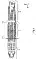
- Fig. 8 shows a top view of an aircraft fuselage which comprises a plurality of cabin structural units 1, 10.
- Two cabin structural units 10 are situated on the forward fuselage area and on the rear fuselage area.
- the first cabin structural unit 1 is situated in the middle of the aircraft fuselage.
- the support frames 11 of the first cabin structural unit 1 and the second cabin structural unit 10 are located at the transition area.
- the cabin structural units 1, 10 are fastened to the aircraft structure 5 using a fixed bearing 4 at the transition areas, for example.
- the wing box which is implemented as especially stiff, is located in the middle area.
- the center of gravity of the aircraft is usually also located in this wing box area, so that small deformation torques arises in the middle of the aircraft fuselage. Therefore, the largest deformations of the aircraft structure 5 arise in the forward aircraft fuselage area and in the rear aircraft fuselage area.
- a gap may be provided, which permits the relative movement of the cabin structural units 1, 10. Because, as in the present example, only three cabin structural units 1, 10 may be situated over the entire aircraft fuselage, only two gaps are necessary to allow the relative movement between the cabin structural units 1, 10.
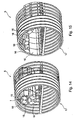
- Fig. 9 and 10 show exemplary aspects of cabin structural units 1 comprising several cabin structural segments 16 that form the cabin structural units 1 and that are connected by hinges 18. Each side of the cabin structural unit 1 provides in this exemplary embodiment one hinge 18, so that the cabin structural unit 1 may be folded as shown in Fig. 10 .
- a cabin structural unit 1 may comprise a plurality of cabin structural segments 16 each connected by hinges 18.
- small packages of a cabin structural unit may be provided in a folded status.
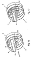
- Fig. 13 to 15 show a possibility for assembling a foldable cabin structural unit. All cabin structural segments 16 may be assembled before guiding the cabin structural unit into the fuselage segment. Referring to Fig. 13 , the structural unit 1 and the cabin installation units 2 may be preassembled outside of the aircraft structure 5. The preassembled cabin structural unit 1 in the folded status thus provides small volume. As shown in Fig. 14 , the folded cabin structural unit 1 may be guided to the predetermined fixing location at the aircraft structure 5. After reaching the predetermined fixing location at the aircraft structure 5 the cabin structural segment 16 may be defolded and fixed to the aircraft structure 5, as shown in Fig. 15 . Thus, an easy and fast way of installing a cabin structural unit may be provided.
- Fig. 16 and 17 shows further possibility of mounting a cabin structural unit 1 to an aircraft structure 5.
- the cabin structural unit 1 may also comprise several cabin structural segments 16 that are guided separately into the aircraft structure 5 to the predetermined location. Next, the cabin structural segment 16, 16" are connected together in order to build the cabin structural unit 1. Thus, at least some parts of the cabin structural unit may be preassembled outside of the aircraft and thus may accelerate the assembling procedure.
- Fig. 18 shows a schematic illustration of a cabin structural unit 1 consisting of several cabin structural segments 16 and several cabin installation elements 2.
- the cabin installation elements 2, such as air ducts and hatracks may be installed outside in the cabin structural unit 1.
- interface elements 21, such as windows adapting units may be installed outside of the aircraft structural unit 1.
- a prefabricated cabin structural unit including all functional elements, such as cabin installation elements 2, connection elements 7 and interface elements 21 may be preassembled outside of an aircraft fuselage, so that a quick and easy installation inside of the aircraft structure 5 may be provided.
- Fig. 19 shows an aircraft cabin consisting of several cabin structural units 1, 10, 10', 10", 10"' that are fixed together. As shown in Fig. 19 , the whole aircraft cabin may be assembled modularly by several cabin structural units 1, 10, 10', 10", 10"'. Each cabin structural unit itself may be preassembled outside of the aircraft and finally assembled together with the cabin structural units 10 in the aircraft structure. Each cabin structural unit 1, 10 itself may be consisting of stiffening faces 9, supporting frames 10, cabin structural segments 16 or connection elements 7, for instance.
- the cabin structural units 1, 10 may be fixed together by fixing elements in an easy manner. Between the cabin structural units, a compensation element 20 may be inserted in order to compensate movements of each single cabin structural unit 1, 10. Each cabin structural unit 1, 10 may be designed in that way, that the compensation element 20 is not visible for the passenger.
- the gap between the cabin structural units 1, 10 may be reduced referring to conventional aircraft cabins due to decoupling the inner cabin structural units from the aircraft structure, so that changes in the volume of the aircraft structure 5 due to pressure or temperature may not affect the inner cabin structural units 1, 10.
- Fig. 20 shows an exemplary build-up of an aircraft fuselage including several cabin structural units 1, 10.
- the so-called door split line may be used as compensation element 20.
- the cabin structural unit 1, 10 may move relatively in opposite direction to each other, and therefore without raising the stress impact of each cabin structural unit 1 and 10 due to these relative movements.
- the cabin structural unit 1 may be attached to the aircraft structure 5 by loose bearings 3 or fixed bearings 4.
- the cabin installation element 2 may also consist of monuments, such as galleys, toilets or other functional sections inside a cabin.
- the cabin installation elements 2 are integrated into the self-supporting cabin structural units 1, 10 and also decoupled from the aircraft structure 5.
- the cabin installation elements 2 move also in this and not in the opposite direction.
- the risk of damages resulting of opposite movements of each cabin structural unit 1 respectively the cabin installation element 2 may be reduced.
- By using a combination of loose and fixed bearings 3 and 4 also the movement in the vertical direction, respectively the z-axis may be reduced, so that merely movements in the longitudinal fuselage direction may be provided.
- Fig. 21 shows a schematic illustration of an interface element 21 connecting cabin installation elements 2 of the cabin structural unit 1 to an aircraft structure 5.
- air ducts as well as window units have to be connected to installations of the aircraft structure 5.
- the window panel 2, 22 it is necessary to provide a interface element 21 to the window openings 23 of the aircraft structure 5.
- the interface element 21 provides this connection between the window panel 22 and the window opening 23.
- the interface element 21 may provide several parts in order to provide sealing and flexible properties.
- the interface element 21 has to be flexible, because relative movements between the aircraft structure and the cabin structural unit 1 may occur.
- the interface element 21 may provide for instance a push-in and snap connection so that in an easy way the cabin installation elements 2 may be connected to functional elements of the fuselage structure 5. By using push-in and snap connections for the connection of the installation elements 2, the assembling time may be reduced.
Claims (14)
- Kabinenstruktureinheit zur Anbringung von Kabineneinbauelementen für ein Luftfahrzeug, die Kabinenstruktureinheit umfassend Kabinenstruktursegmente (16);
wobei die Kabinenstruktureinheit (1) ausgelegt ist, ein Kabineneinbauelement (2) anzubringen;
wobei die Kabinenstruktureinheit (1) selbsttragend ausgelegt ist, so dass keine Unterstützungsverbindungen zwischen einer Luftfahrzeugstruktur (5) und der Kabinenstruktureinheit (1) benötigt werden;
wobei die Kabinenstruktureinheit (1) an einer Fußbodenstruktur (6) des Luftfahrzeuges befestigbar ist; und
wobei die Kabinenstruktursegmente (16) durch Gelenke (18) verbunden sind, um faltbar zu sein. - Kabinenstruktureinheit nach Anspruch 1; umfassend:eine Loslagervorrichtung (3);wobei die Kabinenstruktureinheit (1) ausgelegt ist, unter Verwendung der Loslagervorrichtung (3) an der Fußbodenstruktur (6) befestigt zu werden, so dass die Kabinenstruktureinheit (1) entlang einer Luftfahrzeuglängsrichtung verschiebbar ist.
- Kabinenstruktureinheit nach Anspruch 1 oder 2; ferner umfassend:eine Festlagervorrichtung (4);wobei die Kabinenstruktureinheit (1) an der Fußbodenstruktur (6) unter Verwendung der Festlagereinrichtung (4) befestigbar ist, um Kräfte entlang der Luftfahrzeuglängsachse zu übertragen.
- Kabinenstruktureinheit nach einem der Ansprüche 1 bis 3; ferner umfassend
ein Dämpfungselement;
wobei die Kabinenstruktureinheit (1) ausgelegt ist, an einer Luftfahrzeugstruktur (5; 6) unter Verwendung des Dämpfungselements zur Dämpfung von Schwingungen der Luftfahrzeugstruktur befestigt zu werden. - Kabinenstruktureinheit nach einem der Ansprüche 1 bis 4;
wobei das Kabineneinbauelement (2) ausgelegt ist, integral und einstückig mit der Kabinenstruktureinheit (1) ausgebildet zu sein. - Kabinenstruktureinheit nach einem der Ansprüche 1 bis 5;
wobei die Kabinenstruktureinheit (1) eine Versteifungsfläche (9) umfasst. - Kabinenstruktureinheit nach einem der Ansprüchen 1 bis 6;
wobei die Kabineneinbaueinheit (2) aus der Gruppe bestehend aus Toiletteneinheiten, Kücheneinheiten, Sitzeinheiten, Designelementen, Treppenelementen, Gepäckfächern, Luftbereitstellungseinheiten und Lifteinheiten ausgewählt ist. - Kabinenstruktureinheit nach einem der Ansprüche 1 bis 7;
wobei die Kabinenstruktureinheit (1) ferner Schnittstellenelemente (21) umfasst, wobei die Schnittstellenelemente (21) ausgelegt sind, die Kabineneinbauelemente (2) mit der Luftfahrzeugstruktur (5) oder mit der Bodenstruktur (6) zu verbinden. - Kabinensystem zur Anbringung von Kabineneinbauelementen, wobei das Kabinensystem umfasst:eine erste Kabinenstruktureinheit (1) nach einem der Ansprüche 1 bis 8;eine zweite Kabinenstruktureinheit (10) nach einem der Ansprüche 1 bis 8; undein Ausgleichselement (20);wobei das Ausgleichselement (20) ausgelegt ist, zwischen der ersten Kabinenstruktureinheit (1) und der zweiten Kabinenstruktureinheit (10) zum Ausgleich von Toleranzen eingerichtet zu werden.
- Verfahren zur Anbringung von Kabineneinbauelementen für ein Luftfahrzeug; wobei das Verfahren umfasst:Befestigen eines Kabineneinbauelements (2) an einer Kabinenstruktureinheit (1),wobei die Kabinenstruktureinheit (1) Kabinenstruktursegmente (16) umfasst; undBefestigen der Kabinenstruktureinheit (1) an einer Fußbodenstruktur (6);wobei die Kabinenstruktureinheit (1) ausgelegt ist, selbsttragend zu sein, so dass keine Unterstützungsverbindungen zwischen Luftfahrzeugstruktur (5) und Kabinenstruktureinheit (1) benötigt werden und wobei die Kabinenstruktursegmente (16) durch Gelenke (18) verbunden sind, um faltbar zu sein.
- Verwendung einer Kabinenstruktureinheit zur Anbringung von Kabineneinbauelementen nach einem der Ansprüche 1 bis 8 in einem Luftfahrzeug.
- Luftfahrzeug umfassend eine Kabinenstruktureinheit zur Anbringung von Kabineneinbauelementen nach einem der Ansprüche 1 bis 8.
- Verfahren zum Einbau von einer Kabinenstruktureinheit für ein Luftfahrzeug nach Anspruch 1 bis 8, wobei das Verfahren umfasst:Vormontage der Kabinenstruktureinheit (1) außerhalb der Luftfahrzeugstruktur (5);Führen der vormontierten Kabinenstruktureinheit (1) durch eine Öffnung der Luftfahrzeugstruktur (5);Implementieren der vormontierten Kabinenstruktureinheit (1) an einen vorbestimmten Ort in der Luftfahrzeugstruktur;Fixieren der vormontierten Kabinenstruktureinheit (1) an einer Fußbodenstruktur (6) in der Luftfahrzeugstruktur (5).
- Verfahren nach Anspruch 13,
wobei die vormontierte Kabinenstruktureinheit (1) ausgelegt ist, faltbar zu sein;
wobei das Verfahren ferner umfasst:Falten der vormontierten Kabinenstruktureinheit (1), bevor die vormontierte Kabinenstruktureinheit (1) durch die Öffnung der Luftfahrzeugstruktur geführt wird;Entfalten der vormontierten Kabinenstruktureinheit (1) an einem vorbestimmten Ort in der Luftfahrzeugstruktur (5).
Priority Applications (1)
| Application Number | Priority Date | Filing Date | Title |
|---|---|---|---|
| EP10188976.4A EP2277773B1 (de) | 2006-10-12 | 2007-10-11 | Flugzeug mit einem selbsttragenden Kabinenstrukturbauteil und Verfahren zur Montage eines Kabinenstrukturbauteils in einem Flugzeug |
Applications Claiming Priority (3)
| Application Number | Priority Date | Filing Date | Title |
|---|---|---|---|
| US82919406P | 2006-10-12 | 2006-10-12 | |
| DE102006048376A DE102006048376B4 (de) | 2006-10-12 | 2006-10-12 | Freitragende Kabinenstruktur |
| PCT/EP2007/008847 WO2008043557A1 (en) | 2006-10-12 | 2007-10-11 | Self-supporting interior cabin structure with integrated installation elements |
Related Child Applications (2)
| Application Number | Title | Priority Date | Filing Date |
|---|---|---|---|
| EP10188976.4A Division EP2277773B1 (de) | 2006-10-12 | 2007-10-11 | Flugzeug mit einem selbsttragenden Kabinenstrukturbauteil und Verfahren zur Montage eines Kabinenstrukturbauteils in einem Flugzeug |
| EP10188976.4 Division-Into | 2010-10-27 |
Publications (2)
| Publication Number | Publication Date |
|---|---|
| EP2074024A1 EP2074024A1 (de) | 2009-07-01 |
| EP2074024B1 true EP2074024B1 (de) | 2010-12-08 |
Family
ID=39184889
Family Applications (2)
| Application Number | Title | Priority Date | Filing Date |
|---|---|---|---|
| EP07818918A Not-in-force EP2074024B1 (de) | 2006-10-12 | 2007-10-11 | Freitragende innenkabinenstruktur mit integrierten einbauelementen und verfahren zur installation |
| EP10188976.4A Not-in-force EP2277773B1 (de) | 2006-10-12 | 2007-10-11 | Flugzeug mit einem selbsttragenden Kabinenstrukturbauteil und Verfahren zur Montage eines Kabinenstrukturbauteils in einem Flugzeug |
Family Applications After (1)
| Application Number | Title | Priority Date | Filing Date |
|---|---|---|---|
| EP10188976.4A Not-in-force EP2277773B1 (de) | 2006-10-12 | 2007-10-11 | Flugzeug mit einem selbsttragenden Kabinenstrukturbauteil und Verfahren zur Montage eines Kabinenstrukturbauteils in einem Flugzeug |
Country Status (10)
| Country | Link |
|---|---|
| US (1) | US9387920B2 (de) |
| EP (2) | EP2074024B1 (de) |
| JP (1) | JP2010505695A (de) |
| CN (1) | CN101522517B (de) |
| AT (1) | ATE490909T1 (de) |
| BR (1) | BRPI0717778A2 (de) |
| CA (1) | CA2664780A1 (de) |
| DE (3) | DE102006048376B4 (de) |
| RU (1) | RU2463207C2 (de) |
| WO (1) | WO2008043557A1 (de) |
Families Citing this family (29)
| Publication number | Priority date | Publication date | Assignee | Title |
|---|---|---|---|---|
| DE102006026170B4 (de) * | 2006-06-06 | 2012-06-21 | Airbus Operations Gmbh | Flugzeugrumpfstruktur und Verfahren zu deren Herstellung |
| DE102006026168A1 (de) * | 2006-06-06 | 2008-01-31 | Airbus Deutschland Gmbh | Flugzeugrumpfstruktur und Verfahren zu deren Herstellung |
| DE102006026169B4 (de) * | 2006-06-06 | 2012-06-21 | Airbus Operations Gmbh | Flugzeugrumpfstruktur und Verfahren zu deren Herstellung |
| DE102006048376B4 (de) | 2006-10-12 | 2010-04-15 | Airbus Deutschland Gmbh | Freitragende Kabinenstruktur |
| DE102007018326B4 (de) * | 2007-04-18 | 2010-05-06 | Airbus Deutschland Gmbh | Lagerung zur Befestigung von Treppen in einem Flugzeug |
| DE102007019692B4 (de) * | 2007-04-26 | 2011-06-01 | Airbus Operations Gmbh | Flügel-Rumpf-Sektion eines Flugzeugs |
| DE102007050422B4 (de) | 2007-10-22 | 2012-03-08 | Airbus Operations Gmbh | Flugzeugkomponentenmontagesystem |
| DE102007061423A1 (de) * | 2007-12-20 | 2009-07-02 | Airbus Deutschland Gmbh | Sicherheitskabine |
| FR2929244B1 (fr) * | 2008-03-27 | 2010-07-30 | Airbus | Espace de travail et de rangement a l'arriere d'une cabine d'aeronef |
| WO2009124832A2 (de) | 2008-04-10 | 2009-10-15 | Airbus Operations Gmbh | Flugzeug mit kraftübertragungselement zwischen einem kabinenstrukturelement und einer primärstruktur |
| DE102008038806A1 (de) | 2008-08-13 | 2010-02-25 | Airbus Deutschland Gmbh | Vormontage und Integration von Flugzeugkabinen |
| FR2944262B1 (fr) * | 2009-04-14 | 2013-02-01 | Eads Europ Aeronautic Defence | Procede et dispositif de pre-assemblage d'equipements pour fuselage d'aeronef |
| DE102009023400B4 (de) * | 2009-05-29 | 2014-07-10 | Airbus Operations Gmbh | Haltersystem zur Befestigung einer Flugzeuginterieurkomponente an einer Transportvorrichtung sowie einer Flugzeugstruktur |
| DE102009023401B4 (de) * | 2009-05-29 | 2014-06-26 | Airbus Operations Gmbh | Halter zur Befestigung einer zur Montage in einem Flugzeugrumpfelement vorgesehenen Interieurkomponente an einer Transportvorrichtung sowie Transportvorrichtung |
| DE102009023391A1 (de) * | 2009-05-29 | 2010-12-02 | Airbus Deutschland Gmbh | Verfahren und System zur Montage von Interieurkomponenten in einem Flugzeug |
| DE102009024157A1 (de) | 2009-06-08 | 2011-03-03 | Airbus Operations Gmbh | System und Verfahren zum Herstellen einer Fahrzeugkabine |
| DE102009032078A1 (de) * | 2009-07-07 | 2011-01-13 | Airbus Operations Gmbh | Verfahren zur Reduzierung der Einbauzeiten eines Versorgungskanals |
| DE102010026683A1 (de) * | 2010-07-09 | 2012-01-12 | Airbus Operations Gmbh | Interieurkomponententrägersystem, Flugzeuginterieurkomponentenmodul und Montageverfahren |
| DE102011102364A1 (de) | 2011-05-24 | 2012-11-29 | Airbus Operations Gmbh | Freitragendes Kabinenstruktursegment |
| DE102012001797A1 (de) * | 2012-01-30 | 2013-08-01 | Airbus Operations Gmbh | System und Verfahren zur Montage von Flugzeugsystemkomponenten in der Crown Area eines Flugzeugs |
| US8579076B2 (en) * | 2012-02-29 | 2013-11-12 | Hexcel Corporation | Splicing of curved acoustic honeycomb |
| FR3000031B1 (fr) * | 2012-12-21 | 2015-11-13 | Airbus Operations Sas | Module de soute avionique a plancher superieur integre |
| US9856022B2 (en) * | 2013-09-30 | 2018-01-02 | The Boeing Company | Stowage bin systems |
| AT515159B1 (de) * | 2013-11-20 | 2018-07-15 | Helikopter Air Transp Gmbh | Innenverkleidungsteil und Fertigteil - Baugruppe für eine Luftfahrzeugzelle |
| FR3061129B1 (fr) * | 2016-12-22 | 2019-05-31 | Airbus Operations | Procede de fabrication d'un module d'isolation thermophonique pour aeronef comprenant une etape de cintrage |
| USD902837S1 (en) * | 2017-10-30 | 2020-11-24 | Textron Innovations, Inc. | Large cabin overhead |
| DE102018121623A1 (de) | 2018-09-05 | 2020-03-05 | Airbus Operations Gmbh | Verfahren zum Einbau einer Innenausbaukomponente eines Flugzeugs, Innenausbaukomponente für ein Flugzeug und System zur Montage von Innenausbaukomponenten |
| US11414858B2 (en) * | 2018-12-19 | 2022-08-16 | Rohr, Inc. | Two-way acoustic panel |
| EP3718876B1 (de) * | 2019-04-02 | 2021-11-24 | Airbus Operations GmbH | Paneele für eine kabine eines flugzeugs |
Family Cites Families (46)
| Publication number | Priority date | Publication date | Assignee | Title |
|---|---|---|---|---|
| US2095626A (en) * | 1933-04-20 | 1937-10-12 | Sperry Gyroscope Co Inc | Soundproof cabin for aircraft |
| US3142461A (en) * | 1960-05-26 | 1964-07-28 | A T S Company Ltd | Internal fittings of aircraft |
| US3416274A (en) * | 1965-10-08 | 1968-12-17 | Nasa | Flexibly connected support and skin |
| US4050208A (en) * | 1976-10-04 | 1977-09-27 | The Boeing Company | Aircraft interior ceiling panel assembly and attachment apparatus |
| JPS5647400A (en) * | 1979-09-26 | 1981-04-30 | Kawasaki Heavy Ind Ltd | Boxxshaped cabin structure which can be mounted and demounted to and from aircraft for freight |
| JPS574455A (en) * | 1980-06-06 | 1982-01-11 | Tenryu Industries | Box body with holding rail |
| US4799631A (en) * | 1987-02-18 | 1989-01-24 | Atr International, Inc. | Aircraft shell module |
| US4989809A (en) * | 1988-03-14 | 1991-02-05 | The Boeing Company | Removable aircraft floor structure-reinforcing strongback |
| DE59001679D1 (de) * | 1989-02-06 | 1993-07-15 | Airbus Gmbh | Decken-gepaeckablagen-kombination fuer die passagierkabine eines flugzeuges. |
| US5044578A (en) | 1989-12-27 | 1991-09-03 | White Thomas H | Universal cabin sidewall panel for aircraft |
| US5201831A (en) * | 1991-11-15 | 1993-04-13 | Atr International, Inc. | Aircraft interior shell |
| US5560102A (en) * | 1992-10-13 | 1996-10-01 | The Boeing Company | Panel and fuselage assembly |
| GB2287517B (en) | 1994-03-14 | 1997-04-30 | Kenneth Barry Wilson | Panel assembly system |
| US5549258A (en) * | 1994-12-23 | 1996-08-27 | Heath Tecna Aerospace Company | Retrofit luggage bin assembly compatible with existing aircraft bin supports |
| US5687929A (en) * | 1995-06-29 | 1997-11-18 | Hexcel Corporation | Extensions for storage bins |
| DE19633469C1 (de) * | 1996-08-20 | 1997-09-04 | Daimler Benz Aerospace Airbus | Vorrichtung zum Halten von Ausrüstungsteilen im oberen Bereich von Passagierkabinen, insbesondere von Gepäckablagen in Flugzeugpassagierkabinen |
| DE19639915A1 (de) | 1996-09-27 | 1998-06-10 | Gruenzweig & Hartmann Montage | Hochtemperaturdämmsystem |
| US6158690A (en) * | 1998-10-30 | 2000-12-12 | Sikorsky Aircraft Corporation | Cabin interior panel system for reducing noise transmission in an aircraft |
| RU2191716C2 (ru) * | 1999-04-27 | 2002-10-27 | Открытое акционерное общество Таганрогский авиационный научно-технический комплекс им. Г.М.Бериева | Салон летательного аппарата |
| JP4444422B2 (ja) * | 1999-12-15 | 2010-03-31 | 近畿車輌株式会社 | 鉄道車両の内妻仕切等の取付構造 |
| FR2829102B1 (fr) * | 2001-09-06 | 2004-08-06 | Eurocopter France | Ensemble structurel d'une partie d'un aeronef et aeronef,en particulier un aeronef a voilure tournante, comportant un tel ensemble structurel |
| US6536710B1 (en) * | 2002-02-06 | 2003-03-25 | The Boeing Company | Overhead lattice support structure |
| DE10339508A1 (de) | 2003-07-18 | 2005-03-24 | Telair International Gmbh | Flugzeug |
| US20050044712A1 (en) * | 2003-08-28 | 2005-03-03 | Gideon David E. | Sidewall panel integrated with insulation and air ducts |
| US7252267B2 (en) * | 2003-10-17 | 2007-08-07 | The Boeing Company | Aircraft archway architecture |
| US7380752B2 (en) * | 2003-10-17 | 2008-06-03 | The Boeing Company | Aircraft interior architecture |
| JP4324446B2 (ja) * | 2003-10-27 | 2009-09-02 | 東急車輛製造株式会社 | 車両用艤装構造 |
| US6874731B1 (en) * | 2003-11-05 | 2005-04-05 | The Boeing Company | Modular overhead stowage bin systems and associated methods |
| US6848654B1 (en) * | 2004-01-09 | 2005-02-01 | The Boeing Company | Modular offset aisle overhead crew rest |
| US7270297B2 (en) * | 2004-01-30 | 2007-09-18 | The Boeing Company | Hoist for aircraft cabin construction |
| FR2869289B1 (fr) * | 2004-04-27 | 2007-07-13 | Eads Sogerma Services Sa | Amenagement interieur des parois du fuselage d'un aeronef. |
| US7629026B2 (en) * | 2004-09-03 | 2009-12-08 | Eastman Kodak Company | Thermally controlled fluidic self-assembly |
| EP1647480B1 (de) * | 2004-10-13 | 2010-12-08 | Airbus Operations GmbH | Fugenabdeckung in Flugzeugen |
| JP3734490B2 (ja) * | 2004-12-06 | 2006-01-11 | 株式会社日立製作所 | 鉄道車両用肩部内装パネル |
| US7237749B2 (en) * | 2004-12-14 | 2007-07-03 | The Boeing Company | Collapsible mobile platform interior structure |
| USD539210S1 (en) * | 2005-04-28 | 2007-03-27 | The Boeing Company | Modular archway for an aircraft |
| DE102005023886A1 (de) | 2005-05-24 | 2006-12-07 | Airbus Deutschland Gmbh | Flugzeugrumpf-Montagekonzept |
| GB0512541D0 (en) * | 2005-06-20 | 2005-07-27 | James Park Associates Ltd | Aircraft interior module |
| DE102006039292B4 (de) * | 2006-08-22 | 2010-07-22 | Airbus Deutschland Gmbh | Rahmenelement, Flugzeugklimatisierungssystem sowie Verfahren zur Montage eines Rahmenelements in einem Flugzeug |
| DE102006039291A1 (de) * | 2006-08-22 | 2008-03-13 | Airbus Deutschland Gmbh | Rahmenelement, Gepäckfach sowie Verfahren zur Montage eines Gepäckfachs in einem Flugzeug |
| DE102006039290A1 (de) * | 2006-08-22 | 2008-03-13 | Airbus Deutschland Gmbh | Rahmenelement, Flugzeugkomponentenmontagesystem sowie Verfahren zur Montage einer Komponente in einem Flugzeug |
| DE102006048376B4 (de) | 2006-10-12 | 2010-04-15 | Airbus Deutschland Gmbh | Freitragende Kabinenstruktur |
| US8523110B2 (en) * | 2007-03-28 | 2013-09-03 | Airbus Operations Gmbh | Door frame component of cast titanium and structural fuselage part |
| DE102007050422B4 (de) * | 2007-10-22 | 2012-03-08 | Airbus Operations Gmbh | Flugzeugkomponentenmontagesystem |
| WO2009124832A2 (de) * | 2008-04-10 | 2009-10-15 | Airbus Operations Gmbh | Flugzeug mit kraftübertragungselement zwischen einem kabinenstrukturelement und einer primärstruktur |
| DE102009024157A1 (de) * | 2009-06-08 | 2011-03-03 | Airbus Operations Gmbh | System und Verfahren zum Herstellen einer Fahrzeugkabine |
-
2006
- 2006-10-12 DE DE102006048376A patent/DE102006048376B4/de not_active Expired - Fee Related
-
2007
- 2007-10-11 JP JP2009531775A patent/JP2010505695A/ja active Pending
- 2007-10-11 BR BRPI0717778-0A2A patent/BRPI0717778A2/pt not_active IP Right Cessation
- 2007-10-11 AT AT07818918T patent/ATE490909T1/de not_active IP Right Cessation
- 2007-10-11 RU RU2009117472/11A patent/RU2463207C2/ru not_active IP Right Cessation
- 2007-10-11 CA CA002664780A patent/CA2664780A1/en not_active Abandoned
- 2007-10-11 EP EP07818918A patent/EP2074024B1/de not_active Not-in-force
- 2007-10-11 EP EP10188976.4A patent/EP2277773B1/de not_active Not-in-force
- 2007-10-11 WO PCT/EP2007/008847 patent/WO2008043557A1/en active Application Filing
- 2007-10-11 DE DE602007011085T patent/DE602007011085D1/de active Active
- 2007-10-11 CN CN2007800377398A patent/CN101522517B/zh not_active Expired - Fee Related
-
2008
- 2008-04-10 DE DE102008018249A patent/DE102008018249A1/de not_active Withdrawn
-
2009
- 2009-04-08 US US12/420,761 patent/US9387920B2/en not_active Expired - Fee Related
Also Published As
| Publication number | Publication date |
|---|---|
| EP2277773B1 (de) | 2014-05-07 |
| ATE490909T1 (de) | 2010-12-15 |
| DE102008018249A1 (de) | 2009-04-16 |
| JP2010505695A (ja) | 2010-02-25 |
| EP2277773A3 (de) | 2013-02-20 |
| EP2277773A2 (de) | 2011-01-26 |
| US9387920B2 (en) | 2016-07-12 |
| DE102006048376A1 (de) | 2008-04-17 |
| DE102006048376B4 (de) | 2010-04-15 |
| WO2008043557A1 (en) | 2008-04-17 |
| CN101522517A (zh) | 2009-09-02 |
| EP2074024A1 (de) | 2009-07-01 |
| US20090250554A1 (en) | 2009-10-08 |
| CN101522517B (zh) | 2012-06-06 |
| RU2009117472A (ru) | 2010-11-20 |
| DE602007011085D1 (de) | 2011-01-20 |
| CA2664780A1 (en) | 2008-04-17 |
| RU2463207C2 (ru) | 2012-10-10 |
| BRPI0717778A2 (pt) | 2014-04-22 |
Similar Documents
| Publication | Publication Date | Title |
|---|---|---|
| EP2074024B1 (de) | Freitragende innenkabinenstruktur mit integrierten einbauelementen und verfahren zur installation | |
| US8430362B2 (en) | Aircraft having a force transmission element between a cabin structural element and a primary structure | |
| US8403261B2 (en) | Process for making an aircraft having a floor | |
| US10343768B2 (en) | Landing gear well roof | |
| US9868549B2 (en) | Method for the assembly of an aircraft fuselage and fuselage manufacturing station | |
| US9567089B2 (en) | Hybrid hinge and latch beam | |
| US9359084B2 (en) | Avionics cargo hold module having an upper integrated floor | |
| US20160229513A1 (en) | Aircraft tail cone | |
| US20110036946A1 (en) | Aircraft floor module, structure and method for attaching such a module and aircraft comprising them | |
| US20110001008A1 (en) | Aircraft floor of optimized compactness | |
| CN106660628B (zh) | 具有用于飞机内部的内置门的舱壁组件 | |
| US20170297713A1 (en) | Vehicle Body and Method for Assembling a Vehicle Body | |
| US8991757B2 (en) | Self-supporting cabin structural segment | |
| EP2641804B1 (de) | Selbsttragendes Verbundstoffgehäuse für einen Eisenbahnwagen | |
| US11465747B2 (en) | Overhead support platform system for a vehicle | |
| US10940956B2 (en) | Suspension system for an aircraft auxiliary power unit | |
| US11623727B2 (en) | Aircraft-fuselage structure with contoured adapter arrangement for a door | |
| JP2016117422A (ja) | 客室空間と設備空間との間に介在された耐荷重性の中間床を備えた回転翼航空機の胴体構造 |
Legal Events
| Date | Code | Title | Description |
|---|---|---|---|
| PUAI | Public reference made under article 153(3) epc to a published international application that has entered the european phase |
Free format text: ORIGINAL CODE: 0009012 |
|
| 17P | Request for examination filed |
Effective date: 20090331 |
|
| AK | Designated contracting states |
Kind code of ref document: A1 Designated state(s): AT BE BG CH CY CZ DE DK EE ES FI FR GB GR HU IE IS IT LI LT LU LV MC MT NL PL PT RO SE SI SK TR |
|
| AX | Request for extension of the european patent |
Extension state: AL BA HR MK RS |
|
| 17Q | First examination report despatched |
Effective date: 20091014 |
|
| GRAP | Despatch of communication of intention to grant a patent |
Free format text: ORIGINAL CODE: EPIDOSNIGR1 |
|
| RTI1 | Title (correction) |
Free format text: SELF-SUPPORTING INTERIOR CABIN STRUCTURE WITH INTEGRATED INSTALLATION ELEMENTS AND METHOD OF INSTALLATION |
|
| GRAS | Grant fee paid |
Free format text: ORIGINAL CODE: EPIDOSNIGR3 |
|
| RAP1 | Party data changed (applicant data changed or rights of an application transferred) |
Owner name: AIRBUS OPERATIONS GMBH |
|
| GRAA | (expected) grant |
Free format text: ORIGINAL CODE: 0009210 |
|
| AK | Designated contracting states |
Kind code of ref document: B1 Designated state(s): AT BE BG CH CY CZ DE DK EE ES FI FR GB GR HU IE IS IT LI LT LU LV MC MT NL PL PT RO SE SI SK TR |
|
| REG | Reference to a national code |
Ref country code: GB Ref legal event code: FG4D |
|
| REG | Reference to a national code |
Ref country code: CH Ref legal event code: EP |
|
| REG | Reference to a national code |
Ref country code: IE Ref legal event code: FG4D |
|
| REF | Corresponds to: |
Ref document number: 602007011085 Country of ref document: DE Date of ref document: 20110120 Kind code of ref document: P |
|
| REG | Reference to a national code |
Ref country code: NL Ref legal event code: VDEP Effective date: 20101208 |
|
| PG25 | Lapsed in a contracting state [announced via postgrant information from national office to epo] |
Ref country code: LT Free format text: LAPSE BECAUSE OF FAILURE TO SUBMIT A TRANSLATION OF THE DESCRIPTION OR TO PAY THE FEE WITHIN THE PRESCRIBED TIME-LIMIT Effective date: 20101208 |
|
| LTIE | Lt: invalidation of european patent or patent extension |
Effective date: 20101208 |
|
| PG25 | Lapsed in a contracting state [announced via postgrant information from national office to epo] |
Ref country code: LV Free format text: LAPSE BECAUSE OF FAILURE TO SUBMIT A TRANSLATION OF THE DESCRIPTION OR TO PAY THE FEE WITHIN THE PRESCRIBED TIME-LIMIT Effective date: 20101208 Ref country code: AT Free format text: LAPSE BECAUSE OF FAILURE TO SUBMIT A TRANSLATION OF THE DESCRIPTION OR TO PAY THE FEE WITHIN THE PRESCRIBED TIME-LIMIT Effective date: 20101208 Ref country code: BG Free format text: LAPSE BECAUSE OF FAILURE TO SUBMIT A TRANSLATION OF THE DESCRIPTION OR TO PAY THE FEE WITHIN THE PRESCRIBED TIME-LIMIT Effective date: 20110308 Ref country code: FI Free format text: LAPSE BECAUSE OF FAILURE TO SUBMIT A TRANSLATION OF THE DESCRIPTION OR TO PAY THE FEE WITHIN THE PRESCRIBED TIME-LIMIT Effective date: 20101208 Ref country code: CY Free format text: LAPSE BECAUSE OF FAILURE TO SUBMIT A TRANSLATION OF THE DESCRIPTION OR TO PAY THE FEE WITHIN THE PRESCRIBED TIME-LIMIT Effective date: 20101208 Ref country code: NL Free format text: LAPSE BECAUSE OF FAILURE TO SUBMIT A TRANSLATION OF THE DESCRIPTION OR TO PAY THE FEE WITHIN THE PRESCRIBED TIME-LIMIT Effective date: 20101208 Ref country code: SI Free format text: LAPSE BECAUSE OF FAILURE TO SUBMIT A TRANSLATION OF THE DESCRIPTION OR TO PAY THE FEE WITHIN THE PRESCRIBED TIME-LIMIT Effective date: 20101208 Ref country code: SE Free format text: LAPSE BECAUSE OF FAILURE TO SUBMIT A TRANSLATION OF THE DESCRIPTION OR TO PAY THE FEE WITHIN THE PRESCRIBED TIME-LIMIT Effective date: 20101208 |
|
| PG25 | Lapsed in a contracting state [announced via postgrant information from national office to epo] |
Ref country code: BE Free format text: LAPSE BECAUSE OF FAILURE TO SUBMIT A TRANSLATION OF THE DESCRIPTION OR TO PAY THE FEE WITHIN THE PRESCRIBED TIME-LIMIT Effective date: 20101208 Ref country code: EE Free format text: LAPSE BECAUSE OF FAILURE TO SUBMIT A TRANSLATION OF THE DESCRIPTION OR TO PAY THE FEE WITHIN THE PRESCRIBED TIME-LIMIT Effective date: 20101208 Ref country code: ES Free format text: LAPSE BECAUSE OF FAILURE TO SUBMIT A TRANSLATION OF THE DESCRIPTION OR TO PAY THE FEE WITHIN THE PRESCRIBED TIME-LIMIT Effective date: 20110319 Ref country code: GR Free format text: LAPSE BECAUSE OF FAILURE TO SUBMIT A TRANSLATION OF THE DESCRIPTION OR TO PAY THE FEE WITHIN THE PRESCRIBED TIME-LIMIT Effective date: 20110309 Ref country code: IS Free format text: LAPSE BECAUSE OF FAILURE TO SUBMIT A TRANSLATION OF THE DESCRIPTION OR TO PAY THE FEE WITHIN THE PRESCRIBED TIME-LIMIT Effective date: 20110408 Ref country code: PT Free format text: LAPSE BECAUSE OF FAILURE TO SUBMIT A TRANSLATION OF THE DESCRIPTION OR TO PAY THE FEE WITHIN THE PRESCRIBED TIME-LIMIT Effective date: 20110408 Ref country code: CZ Free format text: LAPSE BECAUSE OF FAILURE TO SUBMIT A TRANSLATION OF THE DESCRIPTION OR TO PAY THE FEE WITHIN THE PRESCRIBED TIME-LIMIT Effective date: 20101208 |
|
| PG25 | Lapsed in a contracting state [announced via postgrant information from national office to epo] |
Ref country code: PL Free format text: LAPSE BECAUSE OF FAILURE TO SUBMIT A TRANSLATION OF THE DESCRIPTION OR TO PAY THE FEE WITHIN THE PRESCRIBED TIME-LIMIT Effective date: 20101208 Ref country code: SK Free format text: LAPSE BECAUSE OF FAILURE TO SUBMIT A TRANSLATION OF THE DESCRIPTION OR TO PAY THE FEE WITHIN THE PRESCRIBED TIME-LIMIT Effective date: 20101208 Ref country code: RO Free format text: LAPSE BECAUSE OF FAILURE TO SUBMIT A TRANSLATION OF THE DESCRIPTION OR TO PAY THE FEE WITHIN THE PRESCRIBED TIME-LIMIT Effective date: 20101208 |
|
| PLBE | No opposition filed within time limit |
Free format text: ORIGINAL CODE: 0009261 |
|
| STAA | Information on the status of an ep patent application or granted ep patent |
Free format text: STATUS: NO OPPOSITION FILED WITHIN TIME LIMIT |
|
| PG25 | Lapsed in a contracting state [announced via postgrant information from national office to epo] |
Ref country code: DK Free format text: LAPSE BECAUSE OF FAILURE TO SUBMIT A TRANSLATION OF THE DESCRIPTION OR TO PAY THE FEE WITHIN THE PRESCRIBED TIME-LIMIT Effective date: 20101208 |
|
| 26N | No opposition filed |
Effective date: 20110909 |
|
| PG25 | Lapsed in a contracting state [announced via postgrant information from national office to epo] |
Ref country code: IT Free format text: LAPSE BECAUSE OF FAILURE TO SUBMIT A TRANSLATION OF THE DESCRIPTION OR TO PAY THE FEE WITHIN THE PRESCRIBED TIME-LIMIT Effective date: 20101208 |
|
| REG | Reference to a national code |
Ref country code: DE Ref legal event code: R097 Ref document number: 602007011085 Country of ref document: DE Effective date: 20110909 |
|
| PG25 | Lapsed in a contracting state [announced via postgrant information from national office to epo] |
Ref country code: MC Free format text: LAPSE BECAUSE OF NON-PAYMENT OF DUE FEES Effective date: 20111031 |
|
| REG | Reference to a national code |
Ref country code: CH Ref legal event code: PL |
|
| PG25 | Lapsed in a contracting state [announced via postgrant information from national office to epo] |
Ref country code: LI Free format text: LAPSE BECAUSE OF NON-PAYMENT OF DUE FEES Effective date: 20111031 Ref country code: CH Free format text: LAPSE BECAUSE OF NON-PAYMENT OF DUE FEES Effective date: 20111031 |
|
| REG | Reference to a national code |
Ref country code: IE Ref legal event code: MM4A |
|
| PG25 | Lapsed in a contracting state [announced via postgrant information from national office to epo] |
Ref country code: IE Free format text: LAPSE BECAUSE OF NON-PAYMENT OF DUE FEES Effective date: 20111011 |
|
| PG25 | Lapsed in a contracting state [announced via postgrant information from national office to epo] |
Ref country code: MT Free format text: LAPSE BECAUSE OF FAILURE TO SUBMIT A TRANSLATION OF THE DESCRIPTION OR TO PAY THE FEE WITHIN THE PRESCRIBED TIME-LIMIT Effective date: 20101208 |
|
| PG25 | Lapsed in a contracting state [announced via postgrant information from national office to epo] |
Ref country code: LU Free format text: LAPSE BECAUSE OF NON-PAYMENT OF DUE FEES Effective date: 20111011 |
|
| PG25 | Lapsed in a contracting state [announced via postgrant information from national office to epo] |
Ref country code: TR Free format text: LAPSE BECAUSE OF FAILURE TO SUBMIT A TRANSLATION OF THE DESCRIPTION OR TO PAY THE FEE WITHIN THE PRESCRIBED TIME-LIMIT Effective date: 20101208 |
|
| PG25 | Lapsed in a contracting state [announced via postgrant information from national office to epo] |
Ref country code: HU Free format text: LAPSE BECAUSE OF FAILURE TO SUBMIT A TRANSLATION OF THE DESCRIPTION OR TO PAY THE FEE WITHIN THE PRESCRIBED TIME-LIMIT Effective date: 20101208 |
|
| REG | Reference to a national code |
Ref country code: FR Ref legal event code: PLFP Year of fee payment: 9 |
|
| REG | Reference to a national code |
Ref country code: DE Ref legal event code: R082 Ref document number: 602007011085 Country of ref document: DE Representative=s name: LKGLOBAL | LORENZ & KOPF PARTG MBB PATENTANWAE, DE Ref country code: DE Ref legal event code: R082 Ref document number: 602007011085 Country of ref document: DE Representative=s name: KOPF WESTENBERGER WACHENHAUSEN PATENTANWAELTE , DE |
|
| REG | Reference to a national code |
Ref country code: FR Ref legal event code: PLFP Year of fee payment: 10 |
|
| PGFP | Annual fee paid to national office [announced via postgrant information from national office to epo] |
Ref country code: DE Payment date: 20161020 Year of fee payment: 10 Ref country code: GB Payment date: 20161020 Year of fee payment: 10 Ref country code: FR Payment date: 20161020 Year of fee payment: 10 |
|
| REG | Reference to a national code |
Ref country code: DE Ref legal event code: R119 Ref document number: 602007011085 Country of ref document: DE |
|
| GBPC | Gb: european patent ceased through non-payment of renewal fee |
Effective date: 20171011 |
|
| REG | Reference to a national code |
Ref country code: FR Ref legal event code: ST Effective date: 20180629 |
|
| PG25 | Lapsed in a contracting state [announced via postgrant information from national office to epo] |
Ref country code: GB Free format text: LAPSE BECAUSE OF NON-PAYMENT OF DUE FEES Effective date: 20171011 Ref country code: DE Free format text: LAPSE BECAUSE OF NON-PAYMENT OF DUE FEES Effective date: 20180501 |
|
| PG25 | Lapsed in a contracting state [announced via postgrant information from national office to epo] |
Ref country code: FR Free format text: LAPSE BECAUSE OF NON-PAYMENT OF DUE FEES Effective date: 20171031 |