EP2072871A2 - Clapet de retenue - Google Patents
Clapet de retenue Download PDFInfo
- Publication number
- EP2072871A2 EP2072871A2 EP20080168702 EP08168702A EP2072871A2 EP 2072871 A2 EP2072871 A2 EP 2072871A2 EP 20080168702 EP20080168702 EP 20080168702 EP 08168702 A EP08168702 A EP 08168702A EP 2072871 A2 EP2072871 A2 EP 2072871A2
- Authority
- EP
- European Patent Office
- Prior art keywords
- valve body
- valve
- body portion
- fluid
- seat
- Prior art date
- Legal status (The legal status is an assumption and is not a legal conclusion. Google has not performed a legal analysis and makes no representation as to the accuracy of the status listed.)
- Withdrawn
Links
Images

Classifications
-
- F—MECHANICAL ENGINEERING; LIGHTING; HEATING; WEAPONS; BLASTING
- F16—ENGINEERING ELEMENTS AND UNITS; GENERAL MEASURES FOR PRODUCING AND MAINTAINING EFFECTIVE FUNCTIONING OF MACHINES OR INSTALLATIONS; THERMAL INSULATION IN GENERAL
- F16K—VALVES; TAPS; COCKS; ACTUATING-FLOATS; DEVICES FOR VENTING OR AERATING
- F16K15/00—Check valves
- F16K15/02—Check valves with guided rigid valve members
- F16K15/06—Check valves with guided rigid valve members with guided stems
- F16K15/063—Check valves with guided rigid valve members with guided stems the valve being loaded by a spring
-
- F—MECHANICAL ENGINEERING; LIGHTING; HEATING; WEAPONS; BLASTING
- F16—ENGINEERING ELEMENTS AND UNITS; GENERAL MEASURES FOR PRODUCING AND MAINTAINING EFFECTIVE FUNCTIONING OF MACHINES OR INSTALLATIONS; THERMAL INSULATION IN GENERAL
- F16K—VALVES; TAPS; COCKS; ACTUATING-FLOATS; DEVICES FOR VENTING OR AERATING
- F16K15/00—Check valves
- F16K15/02—Check valves with guided rigid valve members
- F16K15/08—Check valves with guided rigid valve members shaped as rings
- F16K15/12—Springs for ring valves
-
- F—MECHANICAL ENGINEERING; LIGHTING; HEATING; WEAPONS; BLASTING
- F16—ENGINEERING ELEMENTS AND UNITS; GENERAL MEASURES FOR PRODUCING AND MAINTAINING EFFECTIVE FUNCTIONING OF MACHINES OR INSTALLATIONS; THERMAL INSULATION IN GENERAL
- F16K—VALVES; TAPS; COCKS; ACTUATING-FLOATS; DEVICES FOR VENTING OR AERATING
- F16K25/00—Details relating to contact between valve members and seat
- F16K25/005—Particular materials for seats or closure elements
-
- Y—GENERAL TAGGING OF NEW TECHNOLOGICAL DEVELOPMENTS; GENERAL TAGGING OF CROSS-SECTIONAL TECHNOLOGIES SPANNING OVER SEVERAL SECTIONS OF THE IPC; TECHNICAL SUBJECTS COVERED BY FORMER USPC CROSS-REFERENCE ART COLLECTIONS [XRACs] AND DIGESTS
- Y10—TECHNICAL SUBJECTS COVERED BY FORMER USPC
- Y10T—TECHNICAL SUBJECTS COVERED BY FORMER US CLASSIFICATION
- Y10T137/00—Fluid handling
- Y10T137/7722—Line condition change responsive valves
- Y10T137/7837—Direct response valves [i.e., check valve type]
- Y10T137/7904—Reciprocating valves
- Y10T137/7922—Spring biased
Definitions
- the present invention relates to a check valve for preventing back-flow of fluid.
- a check valve is used to prevent back-flow of the fluid.
- valve bodies of the check valve examples include an elastic valve body made of an elastic material such as rubber and an inelastic valve body made of an inelastic material such as metal, the inelastic valve body being generally referred to as a metal seal.
- a check valve including a valve chamber formed between a fluid inlet and a fluid outlet in a valve casing, a valve seat formed on a fluid inlet side of the valve chamber, and a valve body provided in the valve chamber so as to be movable in a direction in which fluid flows and to be brought into contact with the valve seat from a fluid outlet side, the valve body including, when seen from the fluid inlet side, a first valve body portion made of an inelastic material and a second valve body portion made of an elastic material which respectively have a small diameter and a large diameter, the valve seat including a first valve seat portion and a second valve seat portion with which the first valve body portion and the second valve body portion are brought into contact, respectively (refer to Japanese Patent Application Laid-open No. 2001-349454 , for example).
- a good sealing property is attained by means of the second valve body portion made of an elastic material, which constitutes the valve body, and excellent pressure resistance and durability are attained by means of the first valve bodyportionmade of an inelastic material. That is, it is possible to attain a check valve capable of effectively preventing fluid back-flow when compared with the check valve which relies solely on the seal effected by the elastic valve body or the check valve that relies solely on the seal effected by the inelastic valve body.
- the first valve body portion is made of an inelastic material, that is, made of metal.
- the check valve is relatively heavyweight and limited in applicable range thereof, and is a factor of an increase in cost thereof.
- the inventor of the present invention has continuously conducted studies with reference to Japanese Patent Application Laid-open No. 2001-349454 and the like.
- the present invention was completed on the basis of the finding of the following: a pressure of the fluid through the fluid outlet of the check valve varies in each fluid apparatus; it suffices that the first valve body portion constituting the valve body has a mechanical strength and the pressure resistance so as to be capable of bearing at least the pressure of the fluid through the fluid outlet; and, unlike in the case of the check valve proposed in Japanese Patent Application Laid-open No. 2001-349454 , the first valve body portion is not necessarily made of an inelastic material, that is, not necessarily made of metal.
- a structure of the present invention capable of solving the above-mentioned problem is described as follows.
- a check valve including:
- the check valve of the first aspect is characterized in that the valve casing, the valve seat, the valve body, and an inside of the valve chamber are constituted by parts of one of the following,types:
- the check valve of the first or second aspect is characterized in that:
- the check valve of the first or second aspect is characterized in that the first valve body portion and the second valve body portion are made of the same material, the first valve body portion being formed to be thicker so as to be less easily bent when compared with the second valve body portion, the second valve body portion being formed to be thinner so as to be more easily bent when compared with the first valve body portion.
- the check valve of the fourth aspect is characterized in that the first valve body portion and the second valve body portion are formed integrally with each other and made of the same material.
- the second valve body portion has the flexural modulus which is set to be lower than the flexural modulus of the first valve bodyportion. Therefore, the second valve body portion is easily bent so as to be deformable in conformity with a shape of a seat surface of the second valve seat portion, to thereby be reliably brought into close contact with the second valve seat portion. As a result, a good sealing property can be attained.
- the first valve body portion is set to have a mechanical strength so that the first valve body can mechanically bear the pressure of the fluid on the fluid outlet side. Therefore, in the state of being held in contact with the first valve seat portion, the first valve body portion is less easily bent so as to be capable of sufficiently bearing the pressure of the fluid on the fluid outlet side, in other words, is excellent in pressure resistance and durability.
- the first valve body portion has the mechanical strength so that the first valve body can mechanically bear the pressure of the fluid on the fluid outlet side. Therefore, the material thereof is not limited to metal, and a material can be selected and used therefor so that the first valve body can mechanically bear the pressure of the fluid on the fluid outlet side in accordance therewith. As a result, it is possible to form the first valve body portion so as to be relatively lightweight and not to be limited in applicable range thereof, and possible to select an inexpensive material therefor.
- the valve casing, the valve seat, the valve body, and an inside of the valve chamber are constituted by parts of one of the following types: the parts being made of a material having corrosion resistance and thermal resistance against fluid to be used; the parts being subjected to corrosion resistance surface treatment and thermal resistance surface treatment. Therefore, even when the fluid to be used includes chemicals or has high temperature, the fluid can be used without involving any problem.
- the first valve body portion is made of a resin having a high flexural modulus
- the second valve body portion is made of a resin having a low flexural modulus. Therefore, when a resin having corrosion resistance and thermal resistance against fluid to be used is selected, it is unnecessary to perform corrosion resistance surface treatment and thermal resistance surface treatment, which leads to facilitation of manufacture and reduction in weight.
- the first valve body portion and the second valve body portion are made of the same material, the first valve body portion being formed to be thicker than the second valve body portion so as to be less easily bent when compared therewith, the second valve body portion being formed to be thinner than the first valve body portion so as to be more easily bent when compared therewith. Therefore, even when the first valve body portion and the second valve body portion are made of the same material, the second valve body portion has a good sealing property and the first valve body portion exhibits excellent pressure resistance and durability.
- the first valve body portion and the second valve bodyportion are made of the same material, and hence it is unnecessary to prepare the material for each of the first valve body portion and the second valve body portion, which leads to facilitation of manufacture.
- the first valve body portion and the second valve body portion are formed integrally with each other and made of the same material. Therefore, the manufacture process is simplified and the assembly operation is facilitated when compared with those in the case of separately forming the first valve body portion and the second valve body portion.
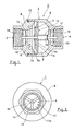
- Fig. 1 is a longitudinal sectional view illustrating an example of a check valve in an opened state according to an embodiment of the present invention
- Fig. 2 is a right-hand side view of Fig. 1
- Fig. 3 is a longitudinal sectional view illustrating a valve body of this embodiment.
- a check valve 1 of this embodiment includes a valve chamber 5 formed between a fluid inlet 3 and a fluid outlet 4 within a valve casing 2, and a valve seat 7 having a valve hole 6 on the fluid inlet 3 side of the valve chamber 5.
- the valve casing 2 includes an inlet member 8 having the fluid inlet 3 and serving as a piping connection portion on the inflow side, and an outlet member 9 having the fluid outlet 4 and serving as a piping connection portion on the outflow passage side.
- the outlet member 9 is threadedly attached to the inlet member 8, with the valve chamber 5 being formed between the fluid inlet 3 of the inlet member 8 and the fluid outlet 4 of the outlet member 9.
- a seal member 10 is attached between the inlet member 8 and the outlet member 9.
- valve seat 7 which opens the valve hole 6 is formed in the inlet member 8 constituting the fluid inlet 3 side of the valve chamber 5, and a valve body 11 which is brought into contact with the valve seat 7 from the fluid outlet 4 side so as to effect valve closure is provided within the valve chamber 5 so as to be freely movable in the direction in which fluid flows.
- the valve body 11 includes, when seen from the fluid inlet 3 side, a first valve body portion 11a and a second valve body portion 11b which have a small diameter and a large diameter, respectively.
- the valve seat 7 includes a first valve seat portion 7a with which the first valve body portion 11a is brought into contact and a second valve seat portion 7b with which the second valve body portion 11b is brought into contact before the first valve body portion 11a is brought into contact with the first valve seat portion 7a.
- the valve body 11 is fixed to a valve shaft 14 passing the center of the valve body 11, the valve shaft 14 having both end portions so as to be supported for being axially movable by shaft support portions 12 and 13 which are provided on the fluid inlet 3 side and the fluid outlet 4 side of the valve casing 2, respectively.
- the valve body 11 moves integrally with the valve shaft 14 so as to be brought into contact with and separated from the valve seat 7.
- the second valve body portion 11b needs to have a flexural modulus which allows deformation for being brought into close contact with the seat surface of the second valve seat portion 7b in conformity with the shape thereof.
- the first valve body portion 11a needs to have a flexural modulus which provides a mechanical strength capable of mechanically bearing the pressure of fluid through the fluid outlet 4.
- the flexural modulus is not necessarily uniform. It suffices that the flexural modulus provides a mechanical strength capable of mechanically bearing the pressure of fluid through the fluid outlet 4 in accordance with the pressure of the fluid through the fluid outlet 4.
- the first valve body portion 11a and the second valve body portion 11b are not particularly limited.
- the first valve body portion 11a is made of a resin having a high flexural modulus
- the second valve body portion 11b is made of a resin having a low flexural modulus.
- Holes 15 and 16 for passing the fluid are respectively provided in the shaft support portions 12 and 13 which movably support the valve shaft 14 to which the valve body 11 is fixed. Further, a spring 17 for biasing the valve body 11 in the direction of being brought into contact with the valve seat 7 is interposed between the valve body 11 and the shaft support portion 13 provided on the fluid outlet 4 side.
- a stopper 18 for regulating the movement amount by which the valve body 11 moves to the fluid outlet 4 side upon receiving the fluid pressure from the fluid inlet 3 side and securing a flow path in the valve chamber 5. When the valve body 11 moves to a predetermined position, the stopper 18 is brought into contact with the shaft support portion 13 provided on the fluid outlet 4 side and supporting the valve shaft 14, thereby restricting further movement.
- parts including the valve casing 2, the valve seat 7, the valve body 11, which constitute the check valve 1, and the shaft support portions 12 and 13, the valve shaft 14, the spring 17, and the stopper 18 which constitute the inside of the valve chamber 5, are made of a material having corrosion resistance and thermal resistance against a fluid to be used, or are subjected to corrosion resistance surface treatment and thermal resistance surface treatment.
- the valve body 11 is biased toward the fluid inlet 3 by the spring 17 so that the first valve body portion 11a is brought into contact with the first valve seat portion 7a and that the second valve body portion 11b is brought into contact with the second valve seat portion 7b.
- the valve body 11 moves against the biasing force of the spring 17 toward the fluid outlet 4, whereby the valve hole 6 of the valve seat 7 is opened so that the fluid is passed therethrough to outflow from the fluid outlet 4 ( Fig. 1 ).
- valve body 11 receives the biasing force of the spring 17 and the pressure of the fluid on the fluid outlet 4 side so as to move toward the fluid inlet 3.
- the second valve body portion 11b is brought into contact with the second valve seat portion 7b, and then the first valve body portion 11a is brought into contact with the first valve seat portion 7a owing to the deformation of the second valve body portion 11b so that the valve hole 6 of the valve seat 7 is closed.
- the back-flow of the fluid on the fluid outlet 4 side is prevented.
- the second valve body portion 11b has a flexural modulus which is set to be lower than a flexural modulus of the first valve body portion 11a. Therefore, the second valve body portion 11b is easily bent so as to be deformed in conformity with the shape of the seat surface of the second valve seat portion 7b, to thereby be reliably brought into close contact with the second valve seat portion 7b.
- the first valve body portion 11a which has a flexural modulus higher than that of the second valve body portion 11b, has a mechanical strength capable of mechanically bearing a pressure of fluid on the fluid outlet 4 side. Therefore, the first valve body portion 11a is less easily bent so as to sufficiently bear the pressure of the fluid on the fluid outlet 4 side in the state of being held in contact with the first valve seat portion 7a.
- the first valve body portion 11a is made of a resin having a high flexural modulus
- the second valve body portion 11b is made of a resin having a low flexural modulus. Therefore, when a resin having corrosion resistance and thermal resistance against fluid to be used is selected, it is unnecessary to perform corrosion resistance surface treatment and thermal resistance surface treatment, which leads to facilitation of manufacture and reduction in weight and cost.
- parts including the valve casing 2, the valve seat 7, the valve body 11 which constitute the check valve 1, and the shaft support portions 12 and 13, the valve shaft 14, the spring 17, and the stopper 18 which constitute the inside of the valve chamber 5, are made of a material having corrosion resistance and thermal resistance against fluid to be used, or are subjected to corrosion resistance surface treatment and thermal resistance surface treatment. Therefore, even when the fluid to be used includes chemicals or has high temperature, the fluid to be used can be used without involving any problem.
- Figs. 4 and 5 are longitudinal sectional views each illustrating another example of the valve body of the check valve according to the present invention.
- the valve body 11 illustrated in Fig. 4 is constituted by the first valve body portion 11a and the second valve body portion 11b which are made of the same material.
- the first valve body portion 11a has a flexural modulus which is larger than a flexural modulus of the second valve body portion 11b
- the first valve body portion 11a is formed to be thicker than the second valve body portion 11b so as to be less easily bent when compared therewith
- the second valve body portion 11b is formed to be thinner than the first valve body portion 11a so as to be more easily bent when compared therewith.
- the second valve body portion 11b to be easily bent needs to have a small thickness so as to be deformable for being brought into contact with the second valve seat portion 7b and to be held in close contact therewith in conformity with the shape of the seat surface of the second valve seat portion 7b. Further, the first valve body portion 11a to be less easily bent needs to have a large thickness which provides a mechanical strength capable of mechanically bearing the pressure of fluid through the fluid outlet 4.
- the first valve body portion 11a and the second valve body portion 11b are made of resins.
- valve body 11 having the above-mentioned structure, even when the first valve body portion 11a and the second valve body portion 11b are made of the same material, the second valve body portion 11b is easily bent so as to be deformed in conformity with the shape of the seat surface of the second valve seat portion 7b, to thereby be reliably brought into close contact with the second valve seat portion 7b. Further, the first valve body portion 11a is capable of sufficiently bearing the pressure of the fluid on the fluid outlet 4 side in the state of being held in contact with the first valve seat portion 7a.
- the valve body 11 illustrated in Fig. 5 is constituted by the first valve body portion 11a and the second valve body portion 11b which are formed integrally with each other of the same material.
- the first valve body portion 11a has a flexural modulus which is larger than a flexural modulus of the second valve body portion 11b
- the first valve body portion 11a is formed to be thicker than the second valve body portion 11b so as to be less easily bent when compared therewith
- the second valve body portion 11b is formed to be thinner than the first valve body portion 11a so as to be more easily bent when compared therewith.
- the second valve body portion 11b to be easily bent needs to have a small thickness so as to be deformable for being brought into contact with the second valve seat portion 7b and to be held in close contact therewith in conformity with the shape of the seat surface of the second valve seat portion 7b. Further, the first valve body portion 11a to be less easily bent needs to have a large thickness having a mechanical strength capable of mechanically bearing the pressure of fluid through the fluid outlet 4.
- the first valve body portion 11a and the second valve body portion 11b are made of resins.
- valve body 11 having the above-mentioned structure, even when the first valve body portion 11a and the second valve body portion 11b are formed integrally with each other of the same material, the second valve body portion 11b is easily bent so as to be deformed in conformity with the shape of the seat surface of the second valve seat portion 7b, to thereby be reliably brought into close contact with the second valve seat portion 7b. Further, the first valve body portion 11a is capable of sufficiently bearing the pressure of the fluid on the fluid outlet 4 side in the state of being held in contact with the first valve seat portion 7a.
Applications Claiming Priority (1)
| Application Number | Priority Date | Filing Date | Title |
|---|---|---|---|
| JP2007318049A JP2009138888A (ja) | 2007-12-10 | 2007-12-10 | 逆止弁 |
Publications (1)
| Publication Number | Publication Date |
|---|---|
| EP2072871A2 true EP2072871A2 (fr) | 2009-06-24 |
Family
ID=40427903
Family Applications (1)
| Application Number | Title | Priority Date | Filing Date |
|---|---|---|---|
| EP20080168702 Withdrawn EP2072871A2 (fr) | 2007-12-10 | 2008-11-10 | Clapet de retenue |
Country Status (6)
| Country | Link |
|---|---|
| US (1) | US20090145497A1 (fr) |
| EP (1) | EP2072871A2 (fr) |
| JP (1) | JP2009138888A (fr) |
| KR (1) | KR20090060938A (fr) |
| CN (1) | CN101457848A (fr) |
| TW (1) | TW200933054A (fr) |
Cited By (6)
| Publication number | Priority date | Publication date | Assignee | Title |
|---|---|---|---|---|
| AT508964B1 (de) * | 2009-11-05 | 2011-07-15 | Tcg Unitech Systemtechnik Gmbh | Rückschlagventil |
| CN102563137A (zh) * | 2011-12-16 | 2012-07-11 | 杭州春江阀门有限公司 | 节能型止回阀 |
| EP2505884A1 (fr) * | 2011-03-28 | 2012-10-03 | Hans Joachim Holm | Clapet anti-retour pour alimentation pour animaux pompable |
| WO2020078772A1 (fr) * | 2018-10-18 | 2020-04-23 | Gea Tuchenhagen Gmbh | Vanne, en particulier clapet antiretour |
| EP3515545A4 (fr) * | 2016-09-22 | 2020-04-29 | Suzhou Skywell Healthcare Information Co., Ltd. | Microsoupape fendue |
| US10948106B2 (en) | 2016-09-22 | 2021-03-16 | Suzhou Skywell Healthcare Information Co, Ltd | Split micro-valve |
Families Citing this family (16)
| Publication number | Priority date | Publication date | Assignee | Title |
|---|---|---|---|---|
| KR100948113B1 (ko) * | 2009-02-17 | 2010-03-18 | 주식회사 유로하우징 | 온열매트용 이동식 보일러 |
| CN102313031A (zh) * | 2010-08-06 | 2012-01-11 | 高砂电气(苏州)有限公司 | 阀构件 |
| CN102252116B (zh) * | 2011-07-18 | 2013-03-20 | 浙江盾安阀门有限公司 | 一种内置膜片式低阻力倒流防止器 |
| JP5982104B2 (ja) * | 2011-09-08 | 2016-08-31 | 株式会社不二工機 | 逆止弁 |
| JP5561492B2 (ja) | 2011-11-04 | 2014-07-30 | Smc株式会社 | チェック弁 |
| CN103867761A (zh) * | 2012-12-14 | 2014-06-18 | 上海新力动力设备研究所 | 一种高温高压耐冲刷热燃气单向阀 |
| US9657854B2 (en) * | 2015-01-28 | 2017-05-23 | Green Drain, Inc. | Sliding skirt valve |
| JP2016151281A (ja) * | 2015-02-16 | 2016-08-22 | 株式会社アトックス | 逆流防止弁 |
| US9746091B2 (en) * | 2015-03-04 | 2017-08-29 | Crane Nuclear, Inc. | Nozzle-type check valve with piston |
| KR20170085234A (ko) * | 2016-01-14 | 2017-07-24 | (주)두쿰 | 강제 잠금 기능을 갖는 체크밸브 |
| US10612676B2 (en) | 2016-01-14 | 2020-04-07 | Do Qoom, Corp, Ltd | Check valve having reverse-direction fluid supply function |
| US10753492B2 (en) * | 2016-10-18 | 2020-08-25 | Miura Co., Ltd. | Check valve |
| AU2018271132A1 (en) | 2017-05-15 | 2020-01-16 | Country Cocky Pty Ltd | Valve for large scale irrigation |
| CN107131331A (zh) * | 2017-07-01 | 2017-09-05 | 宁波华成阀门有限公司 | 一种高强度长寿命止回阀及其制造方法 |
| CN107489792A (zh) * | 2017-08-11 | 2017-12-19 | 江苏金石机械集团有限公司 | 用于高压防卡单流阀的密封装置 |
| WO2023107911A1 (fr) * | 2021-12-09 | 2023-06-15 | Avon Protection Systems, Inc. | Système d'appareil respiratoire |
Citations (1)
| Publication number | Priority date | Publication date | Assignee | Title |
|---|---|---|---|---|
| JP2001349454A (ja) | 2000-06-08 | 2001-12-21 | Miura Co Ltd | 逆止弁および逆止弁の使用方法 |
Family Cites Families (42)
| Publication number | Priority date | Publication date | Assignee | Title |
|---|---|---|---|---|
| US716864A (en) * | 1901-12-23 | 1902-12-30 | Ashton Valve Company | Safety-valve. |
| US1964249A (en) * | 1930-11-13 | 1934-06-26 | Gardner Denver Co | Pump valve |
| US1861420A (en) * | 1930-12-17 | 1932-05-31 | Nat Supply Co | Valve |
| US2103503A (en) * | 1934-07-14 | 1937-12-28 | Oil Well Mfg Corp | Slush pump valve |
| US2139313A (en) * | 1938-03-14 | 1938-12-06 | York Ice Machinery Corp | Valve for compressors |
| US2233649A (en) * | 1938-05-10 | 1941-03-04 | Emsco Derrick & Equip Co | Valve |
| US2223651A (en) * | 1940-08-01 | 1940-12-03 | Oil Well Mfg Corp | Slush-pump valve |
| US2613054A (en) * | 1948-07-08 | 1952-10-07 | United States Steel Corp | Pump valve |
| US2521314A (en) * | 1949-06-10 | 1950-09-05 | Harold L Therolf | Rubber insert type reciprocating valve |
| US2900999A (en) * | 1955-07-21 | 1959-08-25 | Weatherhead Co | Valve seal |
| US2845945A (en) * | 1956-12-06 | 1958-08-05 | Altair Inc | Sealing elements |
| US3027907A (en) * | 1957-03-29 | 1962-04-03 | Luther E Lee | Combination valve |
| US2969651A (en) * | 1958-06-27 | 1961-01-31 | Dole Valve Co | Automatic ice making apparatus |
| US3054422A (en) * | 1958-09-26 | 1962-09-18 | Pellegrino E Napolitano | Fluid seal for pressure responsive valve |
| US3029835A (en) * | 1960-05-17 | 1962-04-17 | Sealol Corp | Check valve with resilient auxiliary seal |
| US3186430A (en) * | 1962-11-15 | 1965-06-01 | Clary Corp | Valve |
| US3344807A (en) * | 1965-08-27 | 1967-10-03 | Lehrer Fritz | Shut-off valve |
| US3444889A (en) * | 1966-08-18 | 1969-05-20 | Exxon Production Research Co | Pump valves |
| US3424427A (en) * | 1966-12-06 | 1969-01-28 | Erich Herion | Fluid-pressure valve |
| US3548868A (en) * | 1968-02-14 | 1970-12-22 | Sealol | Check valve with spring assisted flexible auxiliary valve seat |
| GB1367361A (en) * | 1969-11-26 | 1974-09-18 | Froelich M | Method and apparatus for checking seals |
| US3798073A (en) * | 1972-10-10 | 1974-03-19 | Teledyne Inc | Submersible battery vent plug |
| US4049017A (en) * | 1976-04-12 | 1977-09-20 | Henry Valve Company | Adjustable relief valve |
| CH623905A5 (fr) * | 1977-06-24 | 1981-06-30 | Fischer Ag Georg | |
| US4445534A (en) * | 1980-12-23 | 1984-05-01 | Copeland Corporation | Valve assembly |
| US4368755A (en) * | 1978-12-20 | 1983-01-18 | Copeland Corporation | Valve assembly |
| US4532958A (en) * | 1982-09-30 | 1985-08-06 | Hudson Engineering Company | Check valve having replaceable valve assembly |
| US4637430A (en) * | 1985-12-31 | 1987-01-20 | Nupro Company | Check valve |
| IT211767Z2 (it) * | 1987-06-03 | 1989-04-07 | Itap Spa | Valvola di ritegno e di pescaggio con otturatore autoguidato nel corpo della valvola. |
| US4922957A (en) * | 1989-03-08 | 1990-05-08 | National-Oilwell | Valve with replaceable seal element |
| US5193577A (en) * | 1990-06-25 | 1993-03-16 | Holthuis B.V | Sludge pump valve |
| US5088521A (en) * | 1990-10-29 | 1992-02-18 | Harrisburg, Inc. | Mud pump valve |
| US5226445A (en) * | 1992-05-05 | 1993-07-13 | Halliburton Company | Valve having convex sealing surface and concave seating surface |
| US5343835A (en) * | 1992-12-07 | 1994-09-06 | Charter Manufacturing Company, Inc. | Valve spring retainer |
| US5598009A (en) * | 1994-11-15 | 1997-01-28 | Advanced Micro Devices, Inc. | Hot carrier injection test structure and testing technique for statistical evaluation |
| US5546981A (en) * | 1995-01-12 | 1996-08-20 | Gilbarco, Inc. | Check valve |
| US5913331A (en) * | 1997-06-25 | 1999-06-22 | Zurn Industries, Inc. | Check valve |
| US5848605A (en) * | 1997-11-12 | 1998-12-15 | Cybor Corporation | Check valve |
| JP3846287B2 (ja) * | 2001-11-27 | 2006-11-15 | 三浦工業株式会社 | バルブ |
| JP4151007B2 (ja) * | 2003-05-30 | 2008-09-17 | 三浦工業株式会社 | 逆止弁 |
| JP4269260B2 (ja) * | 2003-06-05 | 2009-05-27 | 三浦工業株式会社 | バルブ |
| JP2005048922A (ja) * | 2003-07-31 | 2005-02-24 | Miura Co Ltd | バルブ |
-
2007
- 2007-12-10 JP JP2007318049A patent/JP2009138888A/ja not_active Withdrawn
-
2008
- 2008-10-30 KR KR1020080107003A patent/KR20090060938A/ko not_active Application Discontinuation
- 2008-11-10 EP EP20080168702 patent/EP2072871A2/fr not_active Withdrawn
- 2008-11-19 TW TW97144633A patent/TW200933054A/zh unknown
- 2008-11-24 US US12/277,070 patent/US20090145497A1/en not_active Abandoned
- 2008-12-10 CN CNA2008101843466A patent/CN101457848A/zh active Pending
Patent Citations (1)
| Publication number | Priority date | Publication date | Assignee | Title |
|---|---|---|---|---|
| JP2001349454A (ja) | 2000-06-08 | 2001-12-21 | Miura Co Ltd | 逆止弁および逆止弁の使用方法 |
Cited By (6)
| Publication number | Priority date | Publication date | Assignee | Title |
|---|---|---|---|---|
| AT508964B1 (de) * | 2009-11-05 | 2011-07-15 | Tcg Unitech Systemtechnik Gmbh | Rückschlagventil |
| EP2505884A1 (fr) * | 2011-03-28 | 2012-10-03 | Hans Joachim Holm | Clapet anti-retour pour alimentation pour animaux pompable |
| CN102563137A (zh) * | 2011-12-16 | 2012-07-11 | 杭州春江阀门有限公司 | 节能型止回阀 |
| EP3515545A4 (fr) * | 2016-09-22 | 2020-04-29 | Suzhou Skywell Healthcare Information Co., Ltd. | Microsoupape fendue |
| US10948106B2 (en) | 2016-09-22 | 2021-03-16 | Suzhou Skywell Healthcare Information Co, Ltd | Split micro-valve |
| WO2020078772A1 (fr) * | 2018-10-18 | 2020-04-23 | Gea Tuchenhagen Gmbh | Vanne, en particulier clapet antiretour |
Also Published As
| Publication number | Publication date |
|---|---|
| US20090145497A1 (en) | 2009-06-11 |
| JP2009138888A (ja) | 2009-06-25 |
| TW200933054A (en) | 2009-08-01 |
| CN101457848A (zh) | 2009-06-17 |
| KR20090060938A (ko) | 2009-06-15 |
Similar Documents
| Publication | Publication Date | Title |
|---|---|---|
| EP2072871A2 (fr) | Clapet de retenue | |
| CN103097785B (zh) | 用于流体阀的阀座装置 | |
| US9945487B2 (en) | Check valve with accelerated closure | |
| JP5593470B2 (ja) | チェックバルブ | |
| US9506576B2 (en) | Check valve apparatuses and methods | |
| KR20120091355A (ko) | 압력 조절기 밸브 시일, 그 시스템 및 방법 | |
| US20130248751A1 (en) | Control valve seal assembly energized by shape memory alloys and fluid valves comprising same | |
| US20150300518A1 (en) | Structure of check valve | |
| US10598291B2 (en) | Guided check valve | |
| US7334603B2 (en) | Check valve | |
| US20200263796A1 (en) | Valves having flexible membranes | |
| JP6872643B2 (ja) | 気体状の媒体を制御および排出するための環状隙間シートを有するガス圧力制限弁 | |
| SK286206B6 (sk) | Guľový ventil | |
| US20100294971A1 (en) | Valve diaphragm | |
| KR101246402B1 (ko) | 역류방지밸브 | |
| KR102629406B1 (ko) | 다이어프램 밸브 | |
| JP5295861B2 (ja) | 逆止弁 | |
| JP2008014378A (ja) | 弁のシール構造 | |
| US10393279B1 (en) | Spring loaded check valve | |
| KR20220093140A (ko) | 편심형 버터플라이 밸브 | |
| RU2744620C1 (ru) | Клапан обратный | |
| KR102604551B1 (ko) | 체크밸브의 탄성부재 부식 방지 장치 | |
| RU212771U1 (ru) | Обратный клапан | |
| CN112780780B (zh) | 阀装置 | |
| WO2024024346A1 (fr) | Clapet anti-retour |
Legal Events
| Date | Code | Title | Description |
|---|---|---|---|
| PUAI | Public reference made under article 153(3) epc to a published international application that has entered the european phase |
Free format text: ORIGINAL CODE: 0009012 |
|
| AK | Designated contracting states |
Kind code of ref document: A2 Designated state(s): AT BE BG CH CY CZ DE DK EE ES FI FR GB GR HR HU IE IS IT LI LT LU LV MC MT NL NO PL PT RO SE SI SK TR |
|
| AX | Request for extension of the european patent |
Extension state: AL BA MK RS |
|
| STAA | Information on the status of an ep patent application or granted ep patent |
Free format text: STATUS: THE APPLICATION IS DEEMED TO BE WITHDRAWN |
|
| 18D | Application deemed to be withdrawn |
Effective date: 20110601 |