EP2072719A2 - Staub- und Diebstahlsicherung, Fahrzeugtüre sowie Fahrzeug mit einer Staub- und Diebstahlsicherung - Google Patents
Staub- und Diebstahlsicherung, Fahrzeugtüre sowie Fahrzeug mit einer Staub- und Diebstahlsicherung Download PDFInfo
- Publication number
- EP2072719A2 EP2072719A2 EP08020493A EP08020493A EP2072719A2 EP 2072719 A2 EP2072719 A2 EP 2072719A2 EP 08020493 A EP08020493 A EP 08020493A EP 08020493 A EP08020493 A EP 08020493A EP 2072719 A2 EP2072719 A2 EP 2072719A2
- Authority
- EP
- European Patent Office
- Prior art keywords
- dust
- theft
- theft protection
- theft device
- seal
- Prior art date
- Legal status (The legal status is an assumption and is not a legal conclusion. Google has not performed a legal analysis and makes no representation as to the accuracy of the status listed.)
- Granted
Links
Images

Classifications
-
- E—FIXED CONSTRUCTIONS
- E05—LOCKS; KEYS; WINDOW OR DOOR FITTINGS; SAFES
- E05B—LOCKS; ACCESSORIES THEREFOR; HANDCUFFS
- E05B77/00—Vehicle locks characterised by special functions or purposes
- E05B77/44—Burglar prevention, e.g. protecting against opening by unauthorised tools
-
- E—FIXED CONSTRUCTIONS
- E05—LOCKS; KEYS; WINDOW OR DOOR FITTINGS; SAFES
- E05B—LOCKS; ACCESSORIES THEREFOR; HANDCUFFS
- E05B79/00—Mounting or connecting vehicle locks or parts thereof
- E05B79/10—Connections between movable lock parts
- E05B79/12—Connections between movable lock parts using connecting rods
-
- E—FIXED CONSTRUCTIONS
- E05—LOCKS; KEYS; WINDOW OR DOOR FITTINGS; SAFES
- E05B—LOCKS; ACCESSORIES THEREFOR; HANDCUFFS
- E05B85/00—Details of vehicle locks not provided for in groups E05B77/00 - E05B83/00
- E05B85/08—Sill-buttons, garnish buttons or inner door lock knobs
Definitions
- the invention relates to a dust and theft protection for a vehicle door with a remote release rod, which is guided through a passage opening of a door panel of the vehicle door, the dust and theft protection having a dust seal and an anti-theft device.
- the invention further relates to a vehicle door and vehicle with a dust and theft protection.
- Dust and theft protection of the type described above are known in the art.
- Such dust and anti-theft devices have a dust seal and an anti-theft device, which are each designed as separate components. These components must be mounted on a door panel, in particular on a door inner panel which is disposed between an outer door panel and a door panel of the door.
- the remote release bar is regularly actuated by a remote control button or lever. The remote release bar is passed through a passage opening of said door panel and connects the remote operation knob or lever to the door lock.
- An anti-theft device for this purpose is usually a kind of cover or cap that covers the area of the Knicks the remote release rod upwards like a roof, thus preventing the engagement of a hook in the kink. The hook slips over the anti-theft device into an area in which it can no longer engage.
- the anti-theft device has to be positioned on the passage opening of the door panel on the side facing the door interior, that is to say the space between the door panel and the door outer panel, and fastened to the door panel by means of fastening means.
- screws are used in the prior art regularly, which engage through the door panel into the anti-theft device.
- the installation of anti-theft device is expensive for the fitter because the door interior is difficult to reach.
- the anti-theft device must be positioned very accurately so that the remote release rod within their Lifting area does not hit the anti-theft device.
- the dust seal is then placed on the passage opening from a side facing the vehicle interior. To attach the dust and theft protection so at least three steps are necessary: positioning the anti-theft device, attaching the anti-theft device to the door panel and placing the dust seal. The installation effort is significant.
- a further problem is that the dust seal can be fastened to the passage opening only by means of relatively small dimensioned fastening means. During operation of the vehicle, the dust seal can be released due to vibrations and vibrations when the door is actuated and when driving, whereby a dust seal of the door gap can no longer be guaranteed.
- Another problem of conventional dust and theft protection is that the door interior must be sealed by a so-called water film against moisture. Due to the stroke of the remote control rod, however, it is necessary to dimension the passage opening comparatively large. Due to the attachment of the conventional dust and anti-theft device, in particular the entanglement of the anti-theft device at the through-hole, the adhesive surface of the water film on the door panel in the region of the through-hole is greatly reduced. This causes difficulties of sealing, which can lead to premature corrosion of the components in the door interior and to moisture ingress into the vehicle interior.
- the object of the invention is thus to provide a dust and theft protection, which can be mounted on the one hand easier than conventional dust and anti-theft devices, on the other hand allows captive attachment of the dust control and also allows adequate sealing of the door interior.
- a dust and anti-theft device according to the invention for a vehicle door with a remote release rod, which is guided through a passage opening of a door panel of the vehicle door, has a dust seal and an anti-theft device.
- dust seal and anti-theft device are designed as one piece mounted dust and theft protection. Dust seal and anti-theft device according to the invention thus form an assembly that is preassembled brought to the assembly line and there is mounted in a single operation on the through hole.
- the amount of work required to mount the dust and theft protection can be significantly reduced.
- the fact that the anti-theft device no longer has to be attached separately to the passage opening also eliminates the problems with the water film, which can be attached over the entire surface to the door panel.
- the design of the dust and theft protection allows as a one-piece assembly to be mounted a trouble-free fixing of the dust seal at the passage opening, so that the dust seal is captive.
- a first advantageous embodiment of the invention provides that the dust seal and anti-theft device are designed as separate components which can be fixed to one another prior to assembly of the dust and anti-theft device at the passage opening.
- the dust seal is usually formed at least in sections of an elastomeric material and the anti-theft device made of a dimensionally stable material that shows no significant deformations in usually acting on the anti-theft forces.
- dust seal and anti-theft device can be fixed to one another via fastening means.
- a combined dust and theft protection assembly can be produced particularly easily.
- Locking means on the dust seal and corresponding counter-locking means on the anti-theft device have proven to be suitable fastening means, locking means and counter-locking means being in operative position with one another during assembly of the dust and anti-theft unit.
- dust seal and anti-theft device can be reliably attached to each other, with appropriately designed locking means, preferably as a circumferential locking means in the form of interlocking encircling circumferential projections allow a particularly good seal the combined dust and theft protection.
- connection of the dust seal and the anti-theft device via latching and counter-locking means is preferably solvable, whereby in the case of a defect of one of the components,
- the dust seal a lightweight and inexpensive repair of dust and theft protection is possible.
- fastening means can be screws, rivets and / or adhesions, by means of which dust seal and anti-theft device can be fastened to one another.
- the anti-theft device is designed as a component projecting through the passage opening of the door panel. In this way, the dust and anti-theft device can be particularly easily mounted by a vehicle interior of the vehicle door.
- the anti-theft device viewed in mounting orientation, has a vehicle vertical axis oriented upward cover surface.
- the covering surface may preferably be beveled or rounded in the manner of a roof or a quarter ball or the like, whereby a particularly reliable deflection of a hook introduced from above can be achieved.
- the anti-theft device in the mounting orientation viewed has an opening directed downwards in the vehicle vertical axis, through which the remote release rod can be easily carried out.
- an anti-theft device can be specified, in which the necessary kink or the necessary bending of the remote release bar in a through door panel and anti-theft device formed interior is arranged. An opening of the door via a hook is thus reliably avoided.
- a further advantageous embodiment of the dust and theft protection provides that the dust seal has a passage opening which is at least as large in the actuation direction as an actuating stroke of the remote release rod. In this way, the remote unlocking can be particularly easy to operate.
- An advantageous embodiment of the dust seal provides that the passage opening is closed dust-tight by two abutting in the rest position dust lips. These dust lips surround the remote release rod and enclose it tightly.
- the dust lips are preferably designed flexibly, which can be achieved that the dust lips of the remote release rod optimally adapt.
- the dust lips may preferably lie with their end faces to each other, whereby a particularly easy production of the dust seal can be achieved, since the dust lips can be made by punching or cutting of a solid material.
- it can further be provided that the dust lips lie side by side with each other, whereby a larger contact surface of the dust lips and a particularly good dust seal can be achieved.
- the dust and theft protection fastening means for fixing the dust and theft protection on the door panel.
- the dust and anti-theft device can be particularly easily set on the door panel.
- a preferred embodiment of the fastening means provides that these are designed as latching means, which the door panel can engage around form-fitting through the passage opening.
- the dust and theft protection can be particularly easily mounted on the door panel, since the combined dust and theft must be used only from a door interior facing side of the door panel in the through hole of the door panel until the locking means the door panel in the Encompass passage opening.
- the assembly can thus be made with a single simple step on the belt.
- fastening means provides that these are designed as screws, rivets and / or bonding, each of which allow a particularly simple installation of the dust and theft protection on the door panel.
- the dust seal is designed such that has a through opening of the door panel fully closing projection, whereby the sealing of the passage opening of the door panel against dust and moisture can be further improved.
- the dust and anti-theft device can also be used with preference in the case of remote-controlled locks via control cables.
- deflection means can be provided on the dust and theft protection, which are required for the deflection of the control cable through the passage opening of the door panel.
- the control cables can be guided in Switzerlandhüllen or be performed without Switzerlandhüllen.
- the invention is also advantageously used in remote unlocking devices, the remote unlocking over a remote control arranged in the region of a window opening or a remote control arranged in the door trim, for example in the region of a door pull handle, can be used.
- An independent idea of the invention provides a vehicle door with a previously described dust and theft protection.
- Another independent idea of the invention relates to a vehicle, in particular a passenger car or truck with a corresponding dust and anti-theft device before.
- FIG. 1 shows a dust and theft protection 2 according to the invention in a state mounted on a door panel 4 of a vehicle door.
- the door panel 4 has a through a door panel 4 and door outer panel facing inside 4.1 and the vehicle interior facing the outside 4.2.
- the dust and theft protection 2 has a dust seal 6 and an anti-theft device 8.
- Dust seal 6 and theft protection 8 form, as in the Figures 3 to 5a is shown, a one-piece assembly, which is mountable from the outside 4.2 of the door panel 4.
- a designed as a slot through opening 10 of the dust seal 6 is penetrated by a remote release rod 12.
- the remote release bar 12 is shown in two positions 12.a and 12.b simultaneously.
- the orientation according to 12.a corresponds to a locking position of the door lock and the orientation according to 12.b an unlocking position of the door lock.
- the passage opening 10 is thereby at two different positions.
- the passage opening 10 of the dust seal is made of an elastomeric material which allows the dust lips 14, 16 to nestle around the remote release bar 12.
- the length of the slot-shaped passage opening 10 is at least as large as a necessary for the operation of the lock stroke of the remote release rod 12th
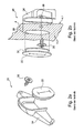
- FIG. 2a shows a conventional dust and theft protection 20 in an exploded view.
- the dust and theft protection 20 is formed in three parts and has a dust seal 22, an anti-theft device 24 and a screw 26.
- FIG. 2b illustrates how the conventional dust and theft protection 20 must be mounted on a through hole 28 of the door panel 4. From the inside 4.1 of the door panel 4, the conventional anti-theft device 24 must be positioned on the through-hole 28 and fastened by means of the screw 26 from the outside of the door 4.2. For this purpose, a corresponding recess 30 for the screw 26 is provided in the anti-theft device 24.
- the dust seal 22 is placed on the outside 4.2. To attach the dust seal 22 to the through-hole, this has a circumferential projection 32.
- FIG. 3 shows the assembly of a dust and theft protection 2 according to the invention at the through hole 28 of the door panel 4.
- the dust seal 2 is inserted from the outside of the door 4.2 in the through hole 28, wherein the anti-theft device 8, the recess 28 of the door panel 4 passes through.
- locking means 40 are provided on the dust and theft protection 2, the form-fitting engage around the door panel 4 after insertion of the dust and theft protection 2 in the recess 28 in the arrow direction and lock with the door panel 4. In this way, the dust and theft protection 2 is fixed to the door panel.
- FIG. 4 shows an exploded view of the dust and theft protection according to the invention 2.
- Anti-theft device 8 and dust seal 6 are made as separate components from their respective application corresponding materials.
- Anti-theft device 8 and dust seal 6 are installed before mounting ( FIG. 3 ), for example via in Figure 4 and Figure 5b to be recognized latching and counter-latching means 42, by means of which dust cap 6 and anti-theft device 8 are latched to each other.
- the anti-theft device 8 has a cover surface 46, which is arranged in mounting orientation of the dust and theft protection 2 upwards. Down the rear, the anti-theft device 8 has an opening 48 for reaching through the remote release rod 12.
- FIG. 5a shows the dust and theft protection 2 according to the invention in assembled representation.
- the dust seal 6 is made of an elastomeric solid material, in which the dust lips 14, 16 and the passage opening 10 are formed by cutting.
- FIG. 5b shows a rear view of the dust and anti-theft device 2 according to the invention.
- the dust seal 6 has a peripheral edge 50, in the mounting position, the recess 28 of the door panel 4 completely encloses.
- the edge 50 can be designed so that it is pressed in the assembled state against the outside 4.2 of the door panel 4.
Landscapes
- Lock And Its Accessories (AREA)
- Cooling, Air Intake And Gas Exhaust, And Fuel Tank Arrangements In Propulsion Units (AREA)
Abstract
Description
- Die Erfindung betrifft eine Staub- und Diebstahlsicherung für eine Fahrzeugtür mit einer Fernentriegelungsstange, die durch eine Durchgangsöffnung eines Türblechs der Fahrzeugtüre geführt ist, wobei die Staub- und Diebstahlsicherung eine Staubdichtung und eine Diebstahlsicherung aufweist. Die Erfindung betrifft weiterhin eine Fahrzeugtüre sowie Fahrzeug mit einer Staub- und Diebstahlsicherung.
- Staub- und Diebstahlsicherungen der vorbezeichneten Art sind im Stand der Technik bekannt. Derartige Staub- und Diebstahlsicherungen weisen eine Staubdichtung und eine Diebstahlsicherung auf, die jeweils als separate Bauteile ausgeführt sind. Diese Bauteile müssen an einem Türblech, insbesondere an einem Türinnenblech, das zwischen einem Türaußenblech und einer Türverkleidung der Tür angeordnet ist, montiert werden. Die Fernentriegelungsstange wird regelmäßig von einem Fernbetätigungsknopf oder -Hebel betätigt. Die Fernentriegelungsstange ist durch eine Durchgangsöffnung besagten Türbleches durchgeführt und verbindet den Fernbetätigungsknopf oder -Hebel mit dem Türschloss.
- Bei Fahrzeugen ohne Diebstahlsicherung war bislang problematisch, dass die Fernentriegelungsstange im Bereich der Durchgangsöffnung abgewinkelt verläuft, wodurch ermöglicht wurde, mittels eines Hakens durch eine Abdichtung einer Fensterscheibe der Fahrzeugtüre hindurch den abgewinkelten Bereich der Fernentriegelungsstange zu greifen und anzuheben. Eine Diebstahlsicherung hierfür stellt regelmäßig eine Art Abdeckung oder Kappe dar, die den Bereich des Knicks der Fernentriegelungsstange nach oben wie ein Dach abdeckt und somit das Eingreifen eines Hakens in den Knick verhindert. Der Haken rutscht über die Diebstahlsicherung ab in einen Bereich, in den er nicht mehr eingreifen kann.
- Zur Abdichtung des durch Türaußenblech und Türblech gebildeten Zwischenraumes gegen Staub ist auf der anderen Seite eine Staubdichtung erforderlich, da durch in der Türverkleidung befindliche Öffnungen Staub in diesen Bereich eintreten kann, was langfristig zu einem Ausfall der im Türinnenbereich befindlichen Elemente wie Schließanlage sowie Fensterheber führen kann.
- Im Stand der Technik ist bekannt, Staubdichtung und Diebstahlsicherung als separate Bauteile auszubilden. Die Diebstahlsicherung muss dabei einer dem Türinnenraum, also dem Raum zwischen Türblech und Türaußenblech zugewandten Seite an der Durchgangsöffnung des Türbleches positioniert werden und mittels Befestigungsmitteln an dem Türblech befestigt werden. Hierzu werden im Stand der Technik regelmäßig Schrauben verwendet, die durch das Türblech hindurch in die Diebstahlsicherung eingreifen. Die Montage der Diebstahlsicherung ist für den Monteur aufwendig, da der Türinnenraum schwer zu erreichen ist. Weiterhin muss die Diebstahlsicherung sehr genau positioniert werden, damit die Fernentriegelungsstange innerhalb ihres Hubbereichs nicht an der Diebstahlsicherung anschlägt. Die Staubabdichtung wird dann von einer dem Fahrzeuginnenraum zugewandten Seite auf die Durchgangsöffnung aufgesetzt. Zur Anbringung der Staub- und Diebstahlsicherung sind also zumindest drei Arbeitsschritte notwendig: Positionieren der Diebstahlsicherung, Befestigen der Diebstahlsicherung am Türblech sowie Aufsetzen der Staubdichtung. Der Montageaufwand ist erheblich.
- Problematisch ist weiterhin, dass die Staubdichtung nur mittels relativ klein dimensionierter Befestigungsmittel an der Durchgangsöffnung befestigbar sind. Im Betrieb des Fahrzeuges kann sich die Staubabdichtung bedingt durch Vibrationen und Erschütterungen bei Betätigung der Tür und im Fahrbetrieb lösen, wodurch eine Staubabdichtung des Türzwischenraumes nicht mehr gewährleistbar ist.
- Ein weiteres Problem herkömmlicher Staub- und Diebstahlsicherungen ist, dass der Türinnenraum durch eine sogenannte Wasserfolie gegen Feuchtigkeit abgedichtet werden muss. Aufgrund des Hubes der Fernbetätigungsstange ist es jedoch erforderlich, die Durchgangsöffnung vergleichsweise groß zu dimensionieren. Bedingt durch die Anbringung der herkömmlichen Staubund Diebstahlsicherung, insbesondere der Verhakung der Diebstahlsicherung an der Durchgangsausnehmung ist die Klebefläche der Wasserfolie an dem Türblech im Bereich der Durchgangsausnehmung stark reduziert. Dies bedingt Schwierigkeiten der Abdichtung, was zu einer vorzeitigen Korrosion der Bauteile im Türinnenbereich sowie zu einem Eindringen von Feuchtigkeit in den Fahrzeuginnenraum führen kann.
- Aufgabe der Erfindung ist es damit, eine Staub- und Diebstahlsicherung anzugeben, die einerseits leichter montiert werden kann als herkömmliche Staub- und Diebstahlsicherungen, die andererseits eine unverlierbare Befestigung der Staubsicherung erlaubt und die darüber hinaus eine ausreichende Abdichtung des Türinnenraums erlaubt.
- Die Aufgabe wird gelöst durch eine Staub- und Diebstahlsicherung gemäß Anspruch 1.
- Eine erfindungsgemäße Staub- und Diebstahlsicherung für eine Fahrzeugtür mit einer Fernentriegelungsstange, die durch eine Durchgangsöffnung eines Türblechs der Fahrzeugtüre geführt ist, weist eine Staubdichtung und eine Diebstahlsicherung auf. Erfindungsgemäß ist vorgesehen, dass Staubdichtung und Diebstahlsicherung als einteilig montierbare Staub- und Diebstahlsicherung ausgebildet sind. Staubabdichtung und Diebstahlsicherung bilden erfindungsgemäß somit eine Baugruppe, die vormontiert an die Montagelinie gebracht wird und die dort in einem einzigen Arbeitsgang an der Durchgangsausnehmung montierbar ist.
- Durch die Montage in einem einzigen Schritt lässt sich der notwendige Arbeitsaufwand zur Montage der Staub- und Diebstahlsicherung erheblich reduzieren. Dadurch, dass die Diebstahlsicherung nicht mehr separat an der Durchgangsöffnung angebracht werden muss, entfallen zusätzlich die Probleme mit der Wasserfolie, die ganzflächig an dem Türblech angebracht werden kann. Weiterhin erlaubt die Ausgestaltung der Staubund Diebstahlsicherung als einteilig zu montierende Baugruppe eine problemlose Festlegung der Staubdichtung an der Durchgangsöffnung, sodass die Staubdichtung unverlierbar ist.
- Eine erste vorteilhafte Ausgestaltung der Erfindung sieht vor, dass Staubdichtung und Diebstahlsicherung als separate Bauteile ausgebildet sind, die vor der Montage der Staub- und Diebstahlsicherung an der Durchgangsöffnung aneinander festlegbar sind. Dies erlaubt die Auswahl geeigneter Materialien für Staubdichtung und Diebstahlsicherung, wobei die Staubdichtung üblicherweise zumindest abschnittsweise aus einem elastomeren Material gebildet ist und die Diebstahlsicherung aus einem formfesten Material, das bei üblicherweise auf die Diebstahlsicherung einwirkenden Kräften keine erheblichen Deformationen erkennen lässt.
- Bevorzugt sind Staubdichtung und Diebstahlsicherung über Befestigungsmittel aneinander festlegbar. Auf diese Weise lässt sich eine kombinierte Staub- und Diebstahlsicherungsbaugruppe besonders leicht herstellen.
- Als geeignete Befestigungsmittel haben sich Rastmittel an der Staubdichtung und entsprechende Gegenrastmittel an der Diebstahlsicherung erwiesen, wobei Rastmittel und Gegenrastmittel bei der Montage der Staub- und Diebstahlsicherungseinheit miteinander in Wirkstellung treten. Auf diese Weise lassen sich Staubdichtung und Diebstahlsicherung zuverlässig aneinander befestigen, wobei entsprechend ausgelegte Rastmittel, bevorzugt als umlaufende Rastmittel in Form von formschlüssig ineinandergreifenden umlaufenden Auskragungen eine besonders gute Abdichtung der kombinierten Staub- und Diebstahlsicherung ermöglichen. Darüber hinaus ist die Verbindung der Staubdichtung und der Diebstahlsicherung über Rast- und Gegenrastmittel bevorzugt lösbar, wodurch im Falle eines Defektes einer der Bauteile, beispielsweise der Staubdichtung, eine leichte und kostengünstige Reparatur der Staub- und Diebstahlsicherung ermöglicht wird.
- Weitere vorteilhafte Befestigungsmittel können Schrauben, Nieten und/oder Verklebungen darstellen, mittels derer Staubdichtung und Diebstahlsicherung aneinander befestigbar sind.
- Nach einer weiteren vorteilhaften Ausgestaltung ist vorgesehen, dass die Diebstahlsicherung als durch die Durchgangsöffnung des Türblechs ragendes Bauteil ausgebildet ist. Auf diese Weise lässt sich die Staub- und Diebstahlsicherung besonders leicht von einer dem Fahrzeuginnenraum der Fahrzeugtüre montieren.
- Weiterhin kann mit Vorteil vorgesehen werden, dass die Diebstahlsicherung in Montageausrichtung betrachtet, eine in Fahrzeughochachse nach oben ausgerichtete Abdeckfläche aufweist. Auf diese Weise lässt sich eine besonders leichte Absicherung der Fernentriegelungsstange nach oben gegen Haken oder dergleichen erreichen. Die Abdeckfläche kann bevorzugt abgeschrägt oder abgerundet nach Art eines Daches oder einer Viertelkugel oder dergleichen ausgestaltet sein, wodurch sich eine besonders zuverlässige Ablenkung eines von oben eingebrachten Hakens erreichen lässt.
- Bevorzugt ist vorgesehen, dass die Diebstahlsicherung in Montageausrichtung betrachtet eine in Fahrzeughochachse nach unten ausgerichtete Öffnung aufweist, durch die die Fernentriegelungsstange ohne weiteres durchgeführt werden kann. Auf diese Weise lässt sich eine Diebstahlsicherung angeben, bei der der notwendige Knick oder die notwendige Biegung der Fernentriegelungsstange in einem durch Türblech und Diebstahlsicherung gebildeten Innenraumes angeordnet ist. Eine Öffnung der Türe über einen Haken wird somit zuverlässig vermieden.
- Eine weitere vorteilhafte Ausgestaltung der Staub- und Diebstahlsicherung sieht vor, dass die Staubabdichtung eine Durchgangsöffnung aufweist, die in Betätigungsrichtung mindestens so groß ist wie ein Betätigungshub der Fernentriegelungsstange. Auf diese Weise lässt sich die Fernentriegelung besonders leicht betätigen.
- Eine vorteilhafte Ausgestaltung der Staubabdichtung sieht vor, dass die Durchgangsöffnung durch zwei in Ruhestellung aneinanderliegende Staublippen staubdicht abgeschlossen wird. Diese Staublippen umgreifen die Fernentriegelungsstange und umschließen diese dicht. Die Staublippen sind bevorzugt flexibel ausgebildet, wodurch sich erreichen lässt, dass sich die Staublippen der Fernentriegelungsstange optimal anpassen. Die Staublippen können bevorzugt mit ihren Stirnflächen aneinander liegen, wodurch sich eine besonders leichte Herstellung der Staubabdichtung erreichen lässt, da die Staublippen durch Aufstanzen oder Schneiden aus einem Vollmaterial hergestellt werden können. Mit Vorteil kann weiterhin vorgesehen sein, dass die Staublippen mit Seitenflächen aneinander liegen, wodurch sich eine größere Kontaktfläche der Staublippen und eine besonders gute Staubabdichtung erreichen lässt.
- Bevorzugt weist die Staub- und Diebstahlsicherung Befestigungsmittel zur Befestigung der Staub- und Diebstahlsicherung an dem Türblech auf. Auf diese Weise lässt sich die Staub- und Diebstahlsicherung besonders leicht an dem Türblech festlegen.
- Eine bevorzugte Ausgestaltung der Befestigungsmittel sieht vor, dass diese als Rastmittel ausgebildet sind, die das Türblech durch die Durchgangsöffnung hindurch formschlüssig umgreifen können. Auf diese Weise lässt sich die Staub- und Diebstahlsicherung besonders leicht an dem Türblech montieren, da die kombinierte Staub- und Diebstahlsicherung lediglich von einer dem Türinnenraum zugewandten Seite des Türbleches in die Durchgangsöffnung des Türbleches eingesetzt werden müssen, bis die Rastmittel das Türblech im Bereich der Durchgangsöffnung umgreifen. Die Montage kann somit mit einem einzelnen einfachen Schritt am Band vorgenommen werden.
- Weitere mögliche vorteilhafte Ausgestaltungen der Befestigungsmittel sieht vor, dass diese als Schrauben, Nieten und/oder Verklebung ausgebildet sind, die jeweils eine besonders einfache Montage der Staub- und Diebstahlsicherung an dem Türblech ermöglichen.
- Bevorzugt ist die Staubabdichtung derart gestaltet, dass sei einen die Durchgangsöffnung des Türblechs vollumfänglich verschließende Auskragung aufweist, wodurch sich die Abdichtung der Durchgangsöffnung des Türblechs gegen Staub und Feuchtigkeit weiter verbessern lässt.
- Alternativ zu einer Fernentriegelungsstange ist die Staub- und Diebstahlsicherung auch mit Vorzug bei über Betätigungszüge fernbetätigbare Schlösser einsetzbar. Hierfür können ggf. Umlenkmittel an der Staub- und Diebstahlsicherung vorgesehen werden, die zur Umlenkung des Betätigungszuges durch die Durchgangsöffnung des Türblechs erforderlich sind. Die Betätigungszüge können dabei in Zughüllen geführt sein oder ohne Zughüllen geführt sein.
- Die Erfindung ist darüber hinaus mit Vorteil einsatzbar bei Fernentriegelungsvorrichtungen, die eine Fernentriegelung über eine im Bereich einer Fensteröffnung angeordneten Fernbetätigung oder einer in der Türverkleidung, beispielsweise im Bereich eines Türzuziehgriffes angeordneten Fernbetätigung einsetzbar.
- Ein unabhängiger Gedanke der Erfindung sieht eine Fahrzeugtüre mit einer zuvor beschriebenen Staub- und Diebstahlsicherung vor.
- Ein weiterer unabhängiger Gedanke der Erfindung betrifft ein Fahrzeug, insbesondere ein Personenkraftfahrzeug oder Lastkraftfahrzeug mit einer entsprechenden Staub- und Diebstahlsicherung vor.
- Weitere Ziele, Merkmale sowie vorteilhafte Anwendungsmöglichkeiten der Erfindung ergeben sich aus der nachfolgenden Beschreibung eines Ausführungsbeispiels anhand der Zeichnungen. Dabei bilden sämtliche beschriebenen und/oder bildlich dargestellten Merkmale in ihrer sinnvollen Kombination den Gegenstand der vorliegenden Erfindung, auch unabhängig von den Patentansprüchen und deren Rückbezügen.
- Es zeigen:
- Figur 1
- eine schematische perspektivische Ansicht einer montierten Staub- und Diebstahlsicherung;
- Figuren 2a, b
- eine herkömmliche Staub- und Diebstahlsicherung nach dem Stand der Technik in Explosionsdarstellung und in Montagedarstellung;
- Figur 3
- eine erfindungsgemäße Staub- und Diebstahlsicherung in Montagedarstellung;
- Figur 4
- eine erfindungsgemäße Staub- und Diebstahlsicherung in Explosionsdarstellung und
- Figuren 5a, b
- zwei unterschiedliche schematische perspektivische Darstellungen der erfindungsgemäßen Staub- und Diebstahlsicherung.
-
Figur 1 zeigt eine erfindungsgemäße Staub- und Diebstahlsicherung 2 in einem an einem Türblech 4 einer Fahrzeugtüre montierten Zustand. Das Türblech 4 weist eine einem durch Türblech 4 und Türaußenblech zugewandte Innenseite 4.1 und eine dem Fahrzeuginnenraum zugewandte Außenseite 4.2 auf. - Die erfindungsgemäße Staub- und Diebstahlsicherung 2 weist eine Staubdichtung 6 sowie eine Diebstahlsicherung 8 auf. Staubdichtung 6 und Diebstahlsicherung 8 bilden, wie in den
Figuren 3 bis 5a dargestellt ist, eine einteilige Baugruppe, die von der Außenseite 4.2 des Türblechs 4 montierbar ist. - Eine als Schlitz ausgestaltete Durchgangsöffnung 10 der Staubdichtung 6 ist von einer Fernentriegelungsstange 12 durchgriffen. Die Fernentriegelungsstange 12 ist in zwei Positionen 12.a und 12.b gleichzeitig dargestellt. Die Ausrichtung gemäß 12.a entspricht dabei einer Verriegelungsstellung des Türschlosses und die Ausrichtung gemäß 12.b einer Entriegelungsstellung des Türschlosses. Die Durchgangsöffnung 10 wird dabei an zwei unterschiedlichen Positionen durchgriffen. Die Durchgangsöffnung 10 der Staubdichtung ist aus einem elastomeren Material gestaltet, die es erlaubt, dass die Staublippen 14, 16 sich um die Fernentriegelungsstange 12 schmiegen. Die Länge der schlitzförmigen Durchgangsöffnung 10 ist dabei mindestens so groß wie ein zur Betätigung des Schlosses notwendiger Hub der Fernentriegelungsstange 12.
-
Figur 2a zeigt eine herkömmliche Staub- und Diebstahlsicherung 20 in einer Explosionsdarstellung. Die Staub- und Diebstahlsicherung 20 ist dreiteilig ausgebildet und weist eine Staubdichtung 22, eine Diebstahlsicherung 24 sowie eine Schraube 26 auf. -
Figur 2b verdeutlicht, wie die herkömmliche Staub- und Diebstahlsicherung 20 an einer Durchgangsausnehmung 28 des Türblechs 4 montiert werden muss. Von der Innenseite 4.1 des Türblechs 4 aus muss die herkömmliche Diebstahlsicherung 24 an der Durchgangsausnehmung 28 positioniert werden und mittels der Schraube 26 von der Türaußenseite 4.2 aus befestigt werden. Hierzu ist in der Diebstahlsicherung 24 eine entsprechende Ausnehmung 30 für die Schraube 26 vorgesehen. - Nach der Montage der Diebstahlsicherung wird von der Außenseite 4.2 aus betrachtet die Staubdichtung 22 aufgesetzt. Zur Befestigung der Staubdichtung 22 an der Durchgangsausnehmung weist diese einen umlaufenden Vorsprung 32 auf.
-
Figur 3 zeigt die Montage einer erfindungsgemäßen Staub- und Diebstahlsicherung 2 an der Durchgangsausnehmung 28 des Türblechs 4. Die Staubdichtung 2 wird von der Türaußenseite 4.2 in die Durchgangsausnehmung 28 eingeführt, wobei die Diebstahlsicherung 8 die Ausnehmung 28 des Türblechs 4 durchgreift. Zur Festlegung der erfindungsgemäßen Staub- und Diebstahlsicherung 2 sind Rastmittel 40 an der Staub- und Diebstahlsicherung 2 vorgesehen, die nach dem Einsetzen der Staubund Diebstahlsicherung 2 in die Ausnehmung 28 in Pfeilrichtung das Türblech 4 formschlüssig umgreifen und mit dem Türblech 4 verrasten. Auf diese Weise ist die Staub- und Diebstahlsicherung 2 an dem Türblech festgelegt. -
Figur 4 zeigt eine Explosionsdarstellung der erfindungsgemäßen Staub- und Diebstahlsicherung 2. Diebstahlsicherung 8 und Staubdichtung 6 sind als separate Bauteile aus ihrem jeweiligen Einsatzzweck entsprechenden Materialien hergestellt. Diebstahlsicherung 8 und Staubdichtung 6 werden vor der Montage (Figur 3 ) aneinander festgelegt, beispielsweise über inFigur 4 und Figur 5b zu erkennende Rast- und Gegenrastmittel 42, mittels derer Staubkappe 6 und Diebstahlsicherung 8 aneinander verrastbar sind. - Die Diebstahlsicherung 8 weist eine Abdeckfläche 46 auf, die in Montageausrichtung der Staub- und Diebstahlsicherung 2 nach oben angeordnet ist. Nach unten hinten weist die Diebstahlsicherung 8 eine Öffnung 48 zum Durchgreifen der Fernentriegelungsstange 12 auf.
-
Figur 5a zeigt die erfindungsgemäße Staub- und Diebstahlsicherung 2 in montierter Darstellung. Die Staubdichtung 6 ist aus einem elastomeren Vollmaterial hergestellt, in das durch Schneiden die Staublippen 14, 16 sowie die Durchgangsöffnung 10 ausgebildet sind. -
Figur 5b zeigt eine rückwärtige Ansicht der erfindungsgemäßen Staub- und Diebstahlsicherung 2. Die Staubdichtung 6 weist einen umlaufenden Rand 50 auf, der in Montagestellung die Ausnehmung 28 des Türblechs 4 vollständig umschließt. Durch das elastomere Material der Staubdichtung 6 kann der Rand 50 so gestaltet werden, dass er in montiertem Zustand gegen die Außenseite 4.2 des Türblechs 4 verpresst ist. -
- 2
- Staub- und Diebstahlsicherung
- 4
- Türblech
- 4.1
- Innenseite des Türblechs
- 4.2
- Außenseite des Türblechs
- 6
- Staubdichtung
- 8
- Diebstahlsicherung
- 10
- Durchgangsöffnung der Staubdichtung
- 12
- Fernentriegelungsstange
- 12.a
- Fernentriegelungsstange in Verriegelungsstellung
- 12.b
- Fernentriegelungsstange in Entriegelungsstellung
- 14,
- Staublippen
- 16
- 20
- Staub- und Diebstahlsicherung
- 22
- Staubdichtung
- 24
- Diebstahlsicherung
- 26
- Schraube
- 28
- Durchgangsöffnung
- 30
- Ausnehmung
- 32
- Vorsprung
- 40
- Rastmittel
- 42
- Rastmittel
- 44
- Gegenrastmittel
- 46
- Abdeckfläche
- 48
- Öffnung
- 50
- Rand
- Y
- Fahrzeughochachse
Claims (15)
- Staub- und Diebstahlsicherung für eine Fahrzeugtür mit einer Fernentriegelungsstange (12), die durch eine Durchgangsöffnung (28) eines Türblechs (4) der Fahrzeugtüre geführt ist, mit einer Staubdichtung (6) und einer Diebstahlsicherung (8), dadurch gekennzeichnet, dass Staubdichtung (6) und Diebstahlsicherung (8) als einteilig montierbare Staub- und Diebstahlsicherung (2) ausgebildet sind.
- Staub- und Diebstahlsicherung nach Anspruch 1, dadurch gekennzeichnet, dass Staubdichtung (6) und Diebstahlsicherung (8) als separate Bauteile ausgebildet sind, die vor der Montage der Staub- und Diebstahlsicherung (2) an der Durchgangsöffnung (28) aneinander festlegbar sind.
- Staub- und Diebstahlsicherung nach einem der vorangegangenen Ansprüche, dadurch gekennzeichnet, dass Staubdichtung (6) und Diebstahlsicherung (8) über Befestigungsmittel (40, 42, 44) aneinander festlegbar sind.
- Staub- und Diebstahlsicherung nach Anspruch 3, dadurch gekennzeichnet, dass die Befestigungsmittel (42, 44) Rastmittel (42) an der Staubdichtung (6) und entsprechende Gegenrastmittel (44) an der Diebstahlsicherung (8) aufweisen, die zusammenwirken können.
- Staub- und Diebstahlsicherung nach Anspruch 3, dadurch gekennzeichnet, dass die Befestigungsmittel als Schrauben, Nieten und/oder Verklebung ausgebildet sind.
- Staub- und Diebstahlsicherung nach einem der vorangegangenen Ansprüche, dadurch gekennzeichnet, dass die Diebstahlsicherung (8) als durch die Durchgangsöffnung (28) ragendes Bauteil ausgebildet ist.
- Staub- und Diebstahlsicherung nach einem der vorangegangenen Ansprüche, dadurch gekennzeichnet, dass die Diebstahlsicherung (8) in Montageausrichtung eine in Fahrzeughochachse (Z) nach oben ausgerichtete Abdeckfläche (46) aufweist.
- Staub- und Diebstahlsicherung nach einem der vorangegangenen Ansprüche, dadurch gekennzeichnet, dass die Diebstahlsicherung (8) in Montageausrichtung eine in Fahrzeughochachse (Z) nach unten ausgerichtete Öffnung (48) aufweist.
- Staub- und Diebstahlsicherung nach einem der vorangegangenen Ansprüche, dadurch gekennzeichnet, dass die Staubabdichtung (6) eine Durchgangsöffnung (10) aufweist, die in Betätigungsrichtung mindestens so groß ist wie ein Betätigungshub der Fernentriegelungsstange (12).
- Staub- und Diebstahlsicherung nach Anspruch 9, dadurch gekennzeichnet, dass die Durchgangsöffnung (10) durch zwei in Ruhestellung aneinanderliegende Staublippen (14, 16) staubdicht verschlossen wird.
- Staub- und Diebstahlsicherung nach einem der vorangegangenen Ansprüche, dadurch gekennzeichnet, dass die Staubund Diebstahlsicherung (2) Befestigungsmittel (40) zur Befestigung an dem Türblech (4) aufweisen.
- Staub- und Diebstahlsicherung nach Anspruch 11, dadurch gekennzeichnet, dass die Befestigungsmittel (2) als Rastmittel (40) ausgebildet sind, die das Türblech (4) durch die Durchgangsöffnung (28) hindurch formschlüssig umgreifen können, oder dass die Befestigungsmittel als Schrauben, Nieten und/oder Verklebung ausgebildet sind.
- Staub- und Diebstahlsicherung nach einem der vorangegangenen Ansprüche, dadurch gekennzeichnet, dass die Staubabdichtung (6) einen die Durchgangsöffnung (28) des Türblechs (4) vollumfänglich umschließenden Rand (50) aufweist.
- Fahrzeugtüre mit einer Staub- und Diebstahlsicherung (2) nach einem der vorangegangenen Ansprüche.
- Fahrzeug, insbesondere Personenkraftfahrzeug mit einer Staub- und Diebstahlsicherung (2) nach einem der vorangegangenen Ansprüche.
Applications Claiming Priority (1)
| Application Number | Priority Date | Filing Date | Title |
|---|---|---|---|
| DE200710062225 DE102007062225A1 (de) | 2007-12-21 | 2007-12-21 | Staub- und Diebstahlsicherung, Fahrzeugtüre sowie Fahrzeug mit einer Staub- und Diebstahlsicherung |
Publications (3)
| Publication Number | Publication Date |
|---|---|
| EP2072719A2 true EP2072719A2 (de) | 2009-06-24 |
| EP2072719A3 EP2072719A3 (de) | 2010-12-08 |
| EP2072719B1 EP2072719B1 (de) | 2012-05-16 |
Family
ID=40456991
Family Applications (1)
| Application Number | Title | Priority Date | Filing Date |
|---|---|---|---|
| EP20080020493 Not-in-force EP2072719B1 (de) | 2007-12-21 | 2008-11-26 | Staub- und Diebstahlsicherung, Fahrzeugtüre sowie Fahrzeug mit einer Staub- und Diebstahlsicherung |
Country Status (3)
| Country | Link |
|---|---|
| EP (1) | EP2072719B1 (de) |
| DE (1) | DE102007062225A1 (de) |
| RU (1) | RU2471054C2 (de) |
Family Cites Families (7)
| Publication number | Priority date | Publication date | Assignee | Title |
|---|---|---|---|---|
| US5435609A (en) * | 1993-09-28 | 1995-07-25 | Igata; Tetzuzo | Anti-theft apparatus for vehicle door locks |
| EP1105603B1 (de) * | 1998-07-29 | 2003-03-05 | Intier Automotive Closures Inc. | Kraftfahrzeugtürverschluss mit verbesserter diebstahlsicherheit |
| DE10224082B4 (de) * | 2002-05-31 | 2006-08-31 | Johnson Controls Interiors Gmbh & Co. Kg | Gestängedurchführung, insbesondere für Betätigungs-Gestänge in Kraftfahrzeugen |
| RU2229576C1 (ru) * | 2002-12-02 | 2004-05-27 | Открытое акционерное общество "АВТОВАЗ" | Устройство блокировки дверного замка с сигнализатором |
| US7108302B2 (en) * | 2003-10-03 | 2006-09-19 | Honda Motor Co., Ltd. | Anti-theft sill knob housing and cable assembly for a vehicle |
| FR2868105B1 (fr) * | 2004-03-25 | 2006-06-30 | Valeo Securite Habitacle Sas | Dipositif d'entrainement pour l'actionnement d'une serrure par un verrou |
| DE102005032926B4 (de) * | 2005-07-14 | 2007-05-16 | Daimler Chrysler Ag | Schließanlage für einen Fahrzeug-Heckdeckel |
-
2007
- 2007-12-21 DE DE200710062225 patent/DE102007062225A1/de not_active Withdrawn
-
2008
- 2008-11-26 EP EP20080020493 patent/EP2072719B1/de not_active Not-in-force
- 2008-12-19 RU RU2008150565/11A patent/RU2471054C2/ru not_active IP Right Cessation
Also Published As
| Publication number | Publication date |
|---|---|
| RU2008150565A (ru) | 2010-06-27 |
| EP2072719B1 (de) | 2012-05-16 |
| DE102007062225A1 (de) | 2009-09-03 |
| RU2471054C2 (ru) | 2012-12-27 |
| EP2072719A3 (de) | 2010-12-08 |
Similar Documents
| Publication | Publication Date | Title |
|---|---|---|
| EP3469175B1 (de) | Türgriffmodul für ein kraftfahrzeug | |
| EP3464764B1 (de) | Kraftfahrzeugschloss | |
| DE4401413C2 (de) | Fahrzeugtür | |
| WO2009015903A2 (de) | Türmodul für fahrzeugtür und montageverfahren | |
| EP2318225B1 (de) | Türanordnung und montageverfahren für eine türanordnung | |
| DE102009056921A1 (de) | Griffmodul für eine Kraftfahrzeugtür | |
| EP1088142A2 (de) | Vorrichtung zum verbinden eines aussengriffs mit einem schliesssystem | |
| DE19848746C2 (de) | System zur Verbindung von Wandlamellen einer Aufzugskabine | |
| EP1706564B1 (de) | Kraftfahrzeug-türschloss | |
| EP2072719B1 (de) | Staub- und Diebstahlsicherung, Fahrzeugtüre sowie Fahrzeug mit einer Staub- und Diebstahlsicherung | |
| EP3688257A1 (de) | Kraftfahrzeugschloss | |
| DE19644155B4 (de) | Kraftfahrzeugtür mit Türaußenblech, Türinnenblech und Bauteilträger für das Türschloß | |
| DE102007007457B4 (de) | Innenverkleidung für eine Kraftfahrzeugtür | |
| DE102010035750A1 (de) | Klebeverbindung zwischen Schloss und Fahrzeugtür | |
| DE102006059583B4 (de) | Verriegelungsvorrichtung für eine Motorhaube | |
| EP1960220A1 (de) | Rollokupplung für ein fahrzeugsonnendachrollo, sowie rolloband, sowie fahrzeugsonnendachrollo | |
| DE102010026764A1 (de) | Betätigungseinrichtung für eine Verriegelungsvorrichtung eines Kraftwagens | |
| EP1703043A2 (de) | Schliessleistenaggregat für ein Türschloss | |
| DE102009045338B4 (de) | Scheibenwischvorrichtung | |
| DE19925859B4 (de) | Montagehilfe für eine Kraftfahrzeugtürkonstruktion | |
| WO2004050404A2 (de) | Kraftfahrzeugtür | |
| EP3986734B1 (de) | Türmodul einer fahrzeugtür | |
| DE10233802A1 (de) | Kraftfahrzeugschloß-Anordnung | |
| DE102005004647B3 (de) | Überrollschutzsystem für Kraftfahrzeuge mit einem ausfahrbaren Überrollkörper und einer Wiedereinfahrsperre | |
| DE3530861A1 (de) | Einbruchssicherung fuer eine kraftfahrzeugtuer |
Legal Events
| Date | Code | Title | Description |
|---|---|---|---|
| PUAI | Public reference made under article 153(3) epc to a published international application that has entered the european phase |
Free format text: ORIGINAL CODE: 0009012 |
|
| AK | Designated contracting states |
Kind code of ref document: A2 Designated state(s): AT BE BG CH CY CZ DE DK EE ES FI FR GB GR HR HU IE IS IT LI LT LU LV MC MT NL NO PL PT RO SE SI SK TR |
|
| AX | Request for extension of the european patent |
Extension state: AL BA MK RS |
|
| PUAL | Search report despatched |
Free format text: ORIGINAL CODE: 0009013 |
|
| AK | Designated contracting states |
Kind code of ref document: A3 Designated state(s): AT BE BG CH CY CZ DE DK EE ES FI FR GB GR HR HU IE IS IT LI LT LU LV MC MT NL NO PL PT RO SE SI SK TR |
|
| AX | Request for extension of the european patent |
Extension state: AL BA MK RS |
|
| RIC1 | Information provided on ipc code assigned before grant |
Ipc: E05B 65/20 20060101ALI20101103BHEP Ipc: E05B 17/00 20060101AFI20090327BHEP Ipc: E05B 17/20 20060101ALI20101103BHEP |
|
| 17P | Request for examination filed |
Effective date: 20110608 |
|
| RAP1 | Party data changed (applicant data changed or rights of an application transferred) |
Owner name: GM GLOBAL TECHNOLOGY OPERATIONS LLC |
|
| AKX | Designation fees paid |
Designated state(s): AT BE BG CH CY CZ DE DK EE ES FI FR GB GR HR HU IE IS IT LI LT LU LV MC MT NL NO PL PT RO SE SI SK TR |
|
| GRAP | Despatch of communication of intention to grant a patent |
Free format text: ORIGINAL CODE: EPIDOSNIGR1 |
|
| RIC1 | Information provided on ipc code assigned before grant |
Ipc: E05B 65/20 20060101ALI20111228BHEP Ipc: E05B 17/20 20060101ALI20111228BHEP Ipc: E05B 17/00 20060101AFI20111228BHEP |
|
| GRAS | Grant fee paid |
Free format text: ORIGINAL CODE: EPIDOSNIGR3 |
|
| GRAA | (expected) grant |
Free format text: ORIGINAL CODE: 0009210 |
|
| AK | Designated contracting states |
Kind code of ref document: B1 Designated state(s): AT BE BG CH CY CZ DE DK EE ES FI FR GB GR HR HU IE IS IT LI LT LU LV MC MT NL NO PL PT RO SE SI SK TR |
|
| REG | Reference to a national code |
Ref country code: GB Ref legal event code: FG4D Free format text: NOT ENGLISH |
|
| REG | Reference to a national code |
Ref country code: CH Ref legal event code: EP |
|
| REG | Reference to a national code |
Ref country code: AT Ref legal event code: REF Ref document number: 558186 Country of ref document: AT Kind code of ref document: T Effective date: 20120615 |
|
| REG | Reference to a national code |
Ref country code: IE Ref legal event code: FG4D Free format text: LANGUAGE OF EP DOCUMENT: GERMAN |
|
| REG | Reference to a national code |
Ref country code: DE Ref legal event code: R096 Ref document number: 502008007191 Country of ref document: DE Effective date: 20120712 |
|
| REG | Reference to a national code |
Ref country code: NL Ref legal event code: VDEP Effective date: 20120516 |
|
| REG | Reference to a national code |
Ref country code: LT Ref legal event code: MG4D Effective date: 20120516 |
|
| PG25 | Lapsed in a contracting state [announced via postgrant information from national office to epo] |
Ref country code: CY Free format text: LAPSE BECAUSE OF FAILURE TO SUBMIT A TRANSLATION OF THE DESCRIPTION OR TO PAY THE FEE WITHIN THE PRESCRIBED TIME-LIMIT Effective date: 20120516 Ref country code: NO Free format text: LAPSE BECAUSE OF FAILURE TO SUBMIT A TRANSLATION OF THE DESCRIPTION OR TO PAY THE FEE WITHIN THE PRESCRIBED TIME-LIMIT Effective date: 20120816 Ref country code: PL Free format text: LAPSE BECAUSE OF FAILURE TO SUBMIT A TRANSLATION OF THE DESCRIPTION OR TO PAY THE FEE WITHIN THE PRESCRIBED TIME-LIMIT Effective date: 20120516 Ref country code: IS Free format text: LAPSE BECAUSE OF FAILURE TO SUBMIT A TRANSLATION OF THE DESCRIPTION OR TO PAY THE FEE WITHIN THE PRESCRIBED TIME-LIMIT Effective date: 20120916 Ref country code: SE Free format text: LAPSE BECAUSE OF FAILURE TO SUBMIT A TRANSLATION OF THE DESCRIPTION OR TO PAY THE FEE WITHIN THE PRESCRIBED TIME-LIMIT Effective date: 20120516 Ref country code: FI Free format text: LAPSE BECAUSE OF FAILURE TO SUBMIT A TRANSLATION OF THE DESCRIPTION OR TO PAY THE FEE WITHIN THE PRESCRIBED TIME-LIMIT Effective date: 20120516 Ref country code: LT Free format text: LAPSE BECAUSE OF FAILURE TO SUBMIT A TRANSLATION OF THE DESCRIPTION OR TO PAY THE FEE WITHIN THE PRESCRIBED TIME-LIMIT Effective date: 20120516 |
|
| PG25 | Lapsed in a contracting state [announced via postgrant information from national office to epo] |
Ref country code: SI Free format text: LAPSE BECAUSE OF FAILURE TO SUBMIT A TRANSLATION OF THE DESCRIPTION OR TO PAY THE FEE WITHIN THE PRESCRIBED TIME-LIMIT Effective date: 20120516 Ref country code: PT Free format text: LAPSE BECAUSE OF FAILURE TO SUBMIT A TRANSLATION OF THE DESCRIPTION OR TO PAY THE FEE WITHIN THE PRESCRIBED TIME-LIMIT Effective date: 20120917 Ref country code: GR Free format text: LAPSE BECAUSE OF FAILURE TO SUBMIT A TRANSLATION OF THE DESCRIPTION OR TO PAY THE FEE WITHIN THE PRESCRIBED TIME-LIMIT Effective date: 20120817 Ref country code: HR Free format text: LAPSE BECAUSE OF FAILURE TO SUBMIT A TRANSLATION OF THE DESCRIPTION OR TO PAY THE FEE WITHIN THE PRESCRIBED TIME-LIMIT Effective date: 20120516 Ref country code: LV Free format text: LAPSE BECAUSE OF FAILURE TO SUBMIT A TRANSLATION OF THE DESCRIPTION OR TO PAY THE FEE WITHIN THE PRESCRIBED TIME-LIMIT Effective date: 20120516 |
|
| PG25 | Lapsed in a contracting state [announced via postgrant information from national office to epo] |
Ref country code: SK Free format text: LAPSE BECAUSE OF FAILURE TO SUBMIT A TRANSLATION OF THE DESCRIPTION OR TO PAY THE FEE WITHIN THE PRESCRIBED TIME-LIMIT Effective date: 20120516 Ref country code: EE Free format text: LAPSE BECAUSE OF FAILURE TO SUBMIT A TRANSLATION OF THE DESCRIPTION OR TO PAY THE FEE WITHIN THE PRESCRIBED TIME-LIMIT Effective date: 20120516 Ref country code: CZ Free format text: LAPSE BECAUSE OF FAILURE TO SUBMIT A TRANSLATION OF THE DESCRIPTION OR TO PAY THE FEE WITHIN THE PRESCRIBED TIME-LIMIT Effective date: 20120516 Ref country code: RO Free format text: LAPSE BECAUSE OF FAILURE TO SUBMIT A TRANSLATION OF THE DESCRIPTION OR TO PAY THE FEE WITHIN THE PRESCRIBED TIME-LIMIT Effective date: 20120516 Ref country code: NL Free format text: LAPSE BECAUSE OF FAILURE TO SUBMIT A TRANSLATION OF THE DESCRIPTION OR TO PAY THE FEE WITHIN THE PRESCRIBED TIME-LIMIT Effective date: 20120516 Ref country code: DK Free format text: LAPSE BECAUSE OF FAILURE TO SUBMIT A TRANSLATION OF THE DESCRIPTION OR TO PAY THE FEE WITHIN THE PRESCRIBED TIME-LIMIT Effective date: 20120516 |
|
| PG25 | Lapsed in a contracting state [announced via postgrant information from national office to epo] |
Ref country code: IT Free format text: LAPSE BECAUSE OF FAILURE TO SUBMIT A TRANSLATION OF THE DESCRIPTION OR TO PAY THE FEE WITHIN THE PRESCRIBED TIME-LIMIT Effective date: 20120516 |
|
| PLBE | No opposition filed within time limit |
Free format text: ORIGINAL CODE: 0009261 |
|
| STAA | Information on the status of an ep patent application or granted ep patent |
Free format text: STATUS: NO OPPOSITION FILED WITHIN TIME LIMIT |
|
| 26N | No opposition filed |
Effective date: 20130219 |
|
| PG25 | Lapsed in a contracting state [announced via postgrant information from national office to epo] |
Ref country code: ES Free format text: LAPSE BECAUSE OF FAILURE TO SUBMIT A TRANSLATION OF THE DESCRIPTION OR TO PAY THE FEE WITHIN THE PRESCRIBED TIME-LIMIT Effective date: 20120827 |
|
| BERE | Be: lapsed |
Owner name: GM GLOBAL TECHNOLOGY OPERATIONS LLC Effective date: 20121130 |
|
| REG | Reference to a national code |
Ref country code: DE Ref legal event code: R097 Ref document number: 502008007191 Country of ref document: DE Effective date: 20130219 |
|
| REG | Reference to a national code |
Ref country code: CH Ref legal event code: PL |
|
| PG25 | Lapsed in a contracting state [announced via postgrant information from national office to epo] |
Ref country code: BG Free format text: LAPSE BECAUSE OF FAILURE TO SUBMIT A TRANSLATION OF THE DESCRIPTION OR TO PAY THE FEE WITHIN THE PRESCRIBED TIME-LIMIT Effective date: 20120816 Ref country code: CH Free format text: LAPSE BECAUSE OF NON-PAYMENT OF DUE FEES Effective date: 20121130 Ref country code: LI Free format text: LAPSE BECAUSE OF NON-PAYMENT OF DUE FEES Effective date: 20121130 |
|
| REG | Reference to a national code |
Ref country code: IE Ref legal event code: MM4A |
|
| PG25 | Lapsed in a contracting state [announced via postgrant information from national office to epo] |
Ref country code: BE Free format text: LAPSE BECAUSE OF NON-PAYMENT OF DUE FEES Effective date: 20121130 |
|
| PG25 | Lapsed in a contracting state [announced via postgrant information from national office to epo] |
Ref country code: IE Free format text: LAPSE BECAUSE OF NON-PAYMENT OF DUE FEES Effective date: 20121126 |
|
| PG25 | Lapsed in a contracting state [announced via postgrant information from national office to epo] |
Ref country code: MT Free format text: LAPSE BECAUSE OF FAILURE TO SUBMIT A TRANSLATION OF THE DESCRIPTION OR TO PAY THE FEE WITHIN THE PRESCRIBED TIME-LIMIT Effective date: 20120516 |
|
| PG25 | Lapsed in a contracting state [announced via postgrant information from national office to epo] |
Ref country code: TR Free format text: LAPSE BECAUSE OF FAILURE TO SUBMIT A TRANSLATION OF THE DESCRIPTION OR TO PAY THE FEE WITHIN THE PRESCRIBED TIME-LIMIT Effective date: 20120516 Ref country code: MC Free format text: LAPSE BECAUSE OF NON-PAYMENT OF DUE FEES Effective date: 20121130 |
|
| PG25 | Lapsed in a contracting state [announced via postgrant information from national office to epo] |
Ref country code: LU Free format text: LAPSE BECAUSE OF NON-PAYMENT OF DUE FEES Effective date: 20121126 |
|
| PG25 | Lapsed in a contracting state [announced via postgrant information from national office to epo] |
Ref country code: HU Free format text: LAPSE BECAUSE OF FAILURE TO SUBMIT A TRANSLATION OF THE DESCRIPTION OR TO PAY THE FEE WITHIN THE PRESCRIBED TIME-LIMIT Effective date: 20081126 |
|
| REG | Reference to a national code |
Ref country code: AT Ref legal event code: MM01 Ref document number: 558186 Country of ref document: AT Kind code of ref document: T Effective date: 20131126 |
|
| PG25 | Lapsed in a contracting state [announced via postgrant information from national office to epo] |
Ref country code: AT Free format text: LAPSE BECAUSE OF NON-PAYMENT OF DUE FEES Effective date: 20131126 |
|
| REG | Reference to a national code |
Ref country code: FR Ref legal event code: PLFP Year of fee payment: 8 |
|
| PGFP | Annual fee paid to national office [announced via postgrant information from national office to epo] |
Ref country code: GB Payment date: 20151125 Year of fee payment: 8 |
|
| PGFP | Annual fee paid to national office [announced via postgrant information from national office to epo] |
Ref country code: FR Payment date: 20151008 Year of fee payment: 8 |
|
| GBPC | Gb: european patent ceased through non-payment of renewal fee |
Effective date: 20161126 |
|
| REG | Reference to a national code |
Ref country code: FR Ref legal event code: ST Effective date: 20170731 |
|
| PG25 | Lapsed in a contracting state [announced via postgrant information from national office to epo] |
Ref country code: FR Free format text: LAPSE BECAUSE OF NON-PAYMENT OF DUE FEES Effective date: 20161130 |
|
| PG25 | Lapsed in a contracting state [announced via postgrant information from national office to epo] |
Ref country code: GB Free format text: LAPSE BECAUSE OF NON-PAYMENT OF DUE FEES Effective date: 20161126 |
|
| PGFP | Annual fee paid to national office [announced via postgrant information from national office to epo] |
Ref country code: DE Payment date: 20181113 Year of fee payment: 11 |
|
| REG | Reference to a national code |
Ref country code: DE Ref legal event code: R119 Ref document number: 502008007191 Country of ref document: DE |
|
| PG25 | Lapsed in a contracting state [announced via postgrant information from national office to epo] |
Ref country code: DE Free format text: LAPSE BECAUSE OF NON-PAYMENT OF DUE FEES Effective date: 20200603 |