EP2072390B1 - Betätigungsvorrichtung für ein Fahrrad - Google Patents
Betätigungsvorrichtung für ein Fahrrad Download PDFInfo
- Publication number
- EP2072390B1 EP2072390B1 EP08166795A EP08166795A EP2072390B1 EP 2072390 B1 EP2072390 B1 EP 2072390B1 EP 08166795 A EP08166795 A EP 08166795A EP 08166795 A EP08166795 A EP 08166795A EP 2072390 B1 EP2072390 B1 EP 2072390B1
- Authority
- EP
- European Patent Office
- Prior art keywords
- operating member
- actuating
- operating
- movement
- bicycle
- Prior art date
- Legal status (The legal status is an assumption and is not a legal conclusion. Google has not performed a legal analysis and makes no representation as to the accuracy of the status listed.)
- Active
Links
- 230000007246 mechanism Effects 0.000 claims description 72
- 239000000725 suspension Substances 0.000 claims description 66
- 230000004044 response Effects 0.000 claims description 19
- 230000008859 change Effects 0.000 claims description 7
- 238000004804 winding Methods 0.000 description 28
- 230000007935 neutral effect Effects 0.000 description 10
- 239000011435 rock Substances 0.000 description 6
- 230000005540 biological transmission Effects 0.000 description 3
- 210000003811 finger Anatomy 0.000 description 3
- 238000005452 bending Methods 0.000 description 2
- 230000000694 effects Effects 0.000 description 2
- 239000002184 metal Substances 0.000 description 2
- 210000002445 nipple Anatomy 0.000 description 2
- 230000002860 competitive effect Effects 0.000 description 1
- 230000009977 dual effect Effects 0.000 description 1
- 210000004936 left thumb Anatomy 0.000 description 1
- 230000004048 modification Effects 0.000 description 1
- 238000012986 modification Methods 0.000 description 1
Images


Classifications
-
- B—PERFORMING OPERATIONS; TRANSPORTING
- B62—LAND VEHICLES FOR TRAVELLING OTHERWISE THAN ON RAILS
- B62K—CYCLES; CYCLE FRAMES; CYCLE STEERING DEVICES; RIDER-OPERATED TERMINAL CONTROLS SPECIALLY ADAPTED FOR CYCLES; CYCLE AXLE SUSPENSIONS; CYCLE SIDE-CARS, FORECARS, OR THE LIKE
- B62K23/00—Rider-operated controls specially adapted for cycles, i.e. means for initiating control operations, e.g. levers, grips
- B62K23/02—Rider-operated controls specially adapted for cycles, i.e. means for initiating control operations, e.g. levers, grips hand actuated
- B62K23/06—Levers
-
- B—PERFORMING OPERATIONS; TRANSPORTING
- B62—LAND VEHICLES FOR TRAVELLING OTHERWISE THAN ON RAILS
- B62M—RIDER PROPULSION OF WHEELED VEHICLES OR SLEDGES; POWERED PROPULSION OF SLEDGES OR SINGLE-TRACK CYCLES; TRANSMISSIONS SPECIALLY ADAPTED FOR SUCH VEHICLES
- B62M25/00—Actuators for gearing speed-change mechanisms specially adapted for cycles
- B62M25/02—Actuators for gearing speed-change mechanisms specially adapted for cycles with mechanical transmitting systems, e.g. cables, levers
- B62M25/04—Actuators for gearing speed-change mechanisms specially adapted for cycles with mechanical transmitting systems, e.g. cables, levers hand actuated
-
- Y—GENERAL TAGGING OF NEW TECHNOLOGICAL DEVELOPMENTS; GENERAL TAGGING OF CROSS-SECTIONAL TECHNOLOGIES SPANNING OVER SEVERAL SECTIONS OF THE IPC; TECHNICAL SUBJECTS COVERED BY FORMER USPC CROSS-REFERENCE ART COLLECTIONS [XRACs] AND DIGESTS
- Y10—TECHNICAL SUBJECTS COVERED BY FORMER USPC
- Y10T—TECHNICAL SUBJECTS COVERED BY FORMER US CLASSIFICATION
- Y10T74/00—Machine element or mechanism
- Y10T74/20—Control lever and linkage systems
- Y10T74/20396—Hand operated
- Y10T74/20402—Flexible transmitter [e.g., Bowden cable]
- Y10T74/2042—Flexible transmitter [e.g., Bowden cable] and hand operator
- Y10T74/20426—Slidable
Definitions
- This invention generally relates to a bicycle control device. More specifically, the present invention relates to a bicycle control device for a bicycle that is configured to operate both two different component parts of the bicycle.
- Bicycling is becoming an increasingly more popular form of recreation as well as a means of transportation. Moreover, bicycling has become a very popular competitive sport for both amateurs and professionals. Whether the bicycle is used for recreation, transportation or competition, the bicycle industry is constantly improving the various components of the bicycle.
- a bicycle is typically equipped with several component parts that need to be manually operated by the rider.
- Such component parts include gear changing devices and brake devices (examples of the "first component part") as well as suspension devices (example of the “second component part”).
- Conventionally, separate bicycle control devices have been used to operate each of these component parts.
- operating or control devices there are known bicycle operating or control devices that individually operate a brake device or gear changing device and a suspension device (e.g., see Japanese Laid-Open Patent Publication No. 10-53183 ).
- an operating or control device that operates a brake device can also be used to operate a suspension device, the suspension device can be adjusted more easily while the bicycle is being ridden.
- both a brake lever for operating the brakes and a suspension operating member for adjusting the suspension device are attached to a base member (bracket) of the brake bicycle control device.
- the suspension operating member is a lever member that is pivotally attached to the base member in a position that is different from the position where the brake lever is attached.
- One object of the present invention is to enable a rider to operate two different component parts of a bicycle without releasing his or her hand from the operating member.
- a bicycle operating system comprising: a gear changing device configured to be mounted to a bicycle; a suspension device configured to be mounted to the bicycle; and a bicycle control device.
- the bicycle control device is provided for operating a first component part being the gear changing device and a second component part being the suspension device of a bicycle.
- the bicycle control device basically a mounting part configured to be mounted to the bicycle; a first actuating unit disposed on the mounting part and including a first component connecting member that is configured to be connected to the first component part; a second actuating unit disposed on the mounting part and including a second component connecting member that is configured to be connected to the second component part; a first operating member movably coupled to the mounting part and operatively coupled to the first and second actuating units in response to movement of the first operating member with respect to the mounting part; a first movement transmitting mechanism arranged between the first operating member and the first actuating unit to transmit a movement of the first operating member in a first direction to the first actuating unit; and a second movement transmitting mechanism arranged between the first operating member and the second actuating unit to transmit a movement of the first operating member in a second direction that is different from the first direction to the second actuating unit.
- the first actuating unit includes a first actuating member configured to be connected to the first component part and a first positioning mechanism operatively coupled to the first actuating member; and the second actuating unit has a second actuating member configured to be connected to the second component part and a second positioning mechanism operatively coupled to the second actuating member.
- the movement causes the first actuating unit to operate such that the first actuating member (which is connected to the first component part) is positioned by the first positioning mechanism.
- the movement causes the second actuating unit to operate such that the second actuating member (which is connected to the second component part) is positioned by the second positioning mechanism.
- the gear changing device can be made to execute a gear change operation by moving the first operating member in the first direction and the suspension device can be adjusted by moving the first operating member in the second direction.
- both the first component part and the second component part can be operated easily with a single first operating member.
- two component parts that require positioning e.g., a gear changing device and a suspension device, can be operated by operating a single first operating member in different directions and the two component parts can be operated easily without releasing one's hand from the first operating member.
- the bicycle control device is provided such that the first and second directions are opposite rotational directions.
- the first operating member can easily be operated in two directions with a finger because the first and second directions are opposite directions.
- the bicycle control device is further provided with a second operating member movably coupled to the mounting part such that movement of the second operating member with respect to the mounting part results in the first actuating member moving to a first actuation position from a second actuation position as determined by the first positioning mechanism in which the second actuation position that is different from the first actuation position.
- a gear changing device can be operated so as to upshift and downshift.
- the bicycle control device is provided such that the mounting part includes a housing having the first and second actuating units disposed within the housing.
- the bicycle control device is more compact because the two actuating units are installed inside a single housing.
- the structure and assembly of the bicycle control device can be simplified and the weight of the bicycle control device reduced by configuring the bicycle control device such that the two actuating units pivot about a common axis.
- the bicycle control device is provided such that the first operating member is arranged between the first actuating unit and the second actuating unit.
- the movement of the first operating member can be transmitted with a simple structure.
- the bicycle control device is further provided with a first movement transmitting mechanism arranged between the first operating member and the first actuating unit to transmit a movement of the first operating member in the first direction to the first actuating unit; and a second movement transmitting mechanism arranged between the first operating member and the second actuating unit to transmit a movement of the first operating member in the second direction that is different from the first direction to the second actuating unit.
- a first movement transmitting mechanism arranged between the first operating member and the first actuating unit to transmit a movement of the first operating member in the first direction to the first actuating unit
- a second movement transmitting mechanism arranged between the first operating member and the second actuating unit to transmit a movement of the first operating member in the second direction that is different from the first direction to the second actuating unit.
- the bicycle control device is provided such that the first movement transmitting mechanism has a first movement transmitting member movably mounted with respect to the mounting part, and a first protruding part provided on a portion of the first operating member, the first movement transmitting member being engaged with the first protruding part in response to movement of the first operating member in the first direction to operate the first actuating unit; and the second movement transmitting mechanism has a second movement transmitting member movably mounted with respect to the mounting part, and a second protruding part provided on a portion of the first operating member, the second movement transmitting member being engaged with the second protruding part in response to movement of the first operating member in the second direction to operate the second actuating unit.
- the movement of the first operating member is transmitted by the engagement of the first and second protruding parts provided on two opposite sides of the first operating member with the first and second engaging parts.
- the movement of the first operating member can be transmitted with a simple structure.
- the bicycle control device is provided such that the second actuating unit is configured to move alternately between a third actuation position and a fourth actuation position in response to movement of the first operating member in the second direction.
- the second actuating unit can be moved alternately between a third position and a fourth position by simply moving the first operating member in the second direction.
- a second component part can be switched between two different states, e.g., on and off, by operating the first operating member in the second direction.
- a bicycle control device for operating a first component part and a second component part of a bicycle.
- the bicycle control device basically includes a mounting part, a first actuating unit, a second actuating unit, and a first operating member, a first movement transmitting mechanism and a second movement transmitting mechanism.
- the mounting part is configured to be mounted to the bicycle.
- the first actuating unit is disposed on the mounting part and includes a first component connecting member that is configured to be connected to the first component part.
- the second actuating unit is disposed on the mounting part and includes a second component connecting member that is configured to be connected to the second component part.
- the first operating member is movably coupled to the mounting part and operatively coupled to the first and second actuating units in response to movement of the first operating member with respect to the mounting part.
- the first movement transmitting mechanism is arranged between the first operating member and the first actuating unit to transmit a movement of the first operating member in a first direction to the first actuating unit.
- the second movement transmitting mechanism is arranged between the first operating member and the second actuating unit to transmit a movement of the first operating member in a second direction that is different from the first direction to the second actuating unit.
- the bicycle control device is provided such that the first actuating unit includes a first actuating member configured to be connect to the first component part and a first positioning mechanism operatively coupled to the first actuating member; and the second actuating unit has a second actuating member configured to be connect to the second component part and a second positioning mechanism operatively coupled to the second actuating member.
- the first actuating unit when the first operating member is operated in the first direction, the movement of the first operating member is transmitted from the first movement transmitting mechanism to the first actuating unit and the first actuating member (which is configured to connect to the first component part) is positioned by the first positioning mechanism.
- the movement of the first operating member is transmitted from the second movement transmitting mechanism to the second actuating unit and the second actuating member (which is configured to connect to the second component part) is positioned by the second positioning mechanism.
- two component parts that require positioning e.g., a gear changing device and a suspension device, can be operated by operating a single first operating member in different directions and the two component parts can be operated easily without releasing one's hand from the first operating member.
- the bicycle control device is provided such that the first and second directions are opposite rotational directions.
- the first operating member can easily be operated in two directions with a finger because the first and second directions are opposite directions.
- the bicycle control device is further provided with a second operating member movably coupled to the mounting part such that movement of the second operating member with respect to the mounting part results in the first actuating member moving to a first actuation position from a second actuation position as determined by the first positioning mechanism in which the second actuation position that is different from the first actuation position.
- a gear changing device can be operated so as to upshift and downshift.
- the bicycle control device is provided such that the mounting part includes a housing having the first and second actuating units disposed within the housing.
- the bicycle control device is more compact because the two actuating units are installed inside a single housing.
- the structure and assembly of the bicycle control device can be simplified and the weight of the bicycle control device reduced by configuring the bicycle control device such that the two actuating units pivot about a common axis.
- the bicycle control device is provided such that the first operating member is arranged between the first actuating unit and the second actuating unit.
- the movement of the first operating member can be transmitted with a simple structure.
- the bicycle control device is provided such that the first movement transmitting mechanism has a first movement transmitting member movably mounted with respect to the mounting part, and a first protruding part provided on a portion of the first operating member, the first movement transmitting member being engaged with the first protruding part in response to movement of the first operating member in the first direction to operate the first actuating unit; and the second movement transmitting mechanism has a second movement transmitting member movably mounted with respect to the mounting part, and a second protruding part provided on a portion of the first operating member, the second movement transmitting member being engaged with the second protruding part in response to movement of the first operating member in the second direction to operate the second actuating unit.
- first and second movement transmitting mechanisms are arranged between the first operating member and the first and second actuating units, two component parts can be actuated by moving the first operating member in different directions. Consequently, two component parts can be operated easily without releasing one's hand from the first operating member.
- the bicycle control device is provided such that the second actuating unit is configured to move alternately between a third actuation position and a fourth actuation position in response to a movement of the first operating member in the second direction.
- the second actuating unit can be moved alternately between a third position and a fourth position by simply moving the first operating member in the second direction.
- a second component part can be switched between two different states, e.g., on and off, by operating the first operating member in the second direction.
- a bicycle operating system basically includes a gear changing device, a suspension device and a bicycle control device.
- the gear changing device is configured to be mounted to a bicycle.
- the suspension device is configured to be mounted to the bicycle.
- the bicycle control device is operatively coupled to the gear changing device and the suspension device.
- the bicycle control device basically includes a mounting part, a first actuating unit, a second actuating unit and a first operating member.
- the mounting part is configured to be mounted to the bicycle.
- the first actuating unit is disposed on the mounting part and operatively coupled to the gear changing device to change gear positions.
- the second actuating unit is disposed on the mounting part and operatively coupled to the suspension device to change suspension states.
- the first operating member is movably coupled to the mounting part and operatively coupled to the first and second actuating units to operate the first actuating unit when the first operating member is moved in a first direction and to operate the second actuating unit when the first operating member is moved in a second direction that is different from the first direction.
- the movement causes the first actuating unit to operate such that the gear changing device can be shifted.
- the movement causes the second actuating unit to operate such that the suspension device can be adjusted.
- both the gear changing device and the suspension device can be operated by changing the direction in which the first operating member is moved, two devices can be easily operated with a single first operating member.
- a gear changing device and a suspension device can be operated by operating a single first operating member in different directions and the two devices can be operated easily without releasing one's hand from the first operating member.
- the bicycle operating system is provided such that the first and second directions are opposite rotational directions.
- the first operating member can easily be operated in two directions with a finger because the first direction and the second direction are opposite directions
- the bicycle operating system is provided such that the first actuating unit includes a first actuating member configured to be connect to the gear changing device and a first positioning mechanism operatively coupled to the first actuating member, with the first positioning mechanism holding the first actuating member in one of a plurality of actuation positions and the first actuating member being moved in response to the first operating member being moved in the first direction to shift the gear changing device; and the second actuating unit has a second actuating member configured to be connect to the suspension device and a second positioning mechanism operatively coupled to the second actuating member, with the second positioning mechanism holding the second actuating member in one of a plurality of operating positions and the second actuating member being moved in response to the first operating member being moved in the second direction to change an operating state of the suspension device.
- both the first component part and the second component part can be operated easily with a single first operating member.
- two component parts that require positioning e.g., a gear changing device and a suspension device, can be operated by operating a single first operating member in different directions and the two component parts can be operated easily without releasing one's hand from the first operating member.
- both the gear changing device and the suspension device can be operated by changing the direction in which the first operating member is moved, two devices can be easily operated with a single first operating member.
- a gear changing device and a suspension device can be operated by operating a single first operating member in different directions and the two devices can be operated easily without releasing one's hand from the first operating member.
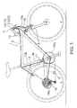
- Figure 1 is a side elevational view of a bicycle equipped with a bicycle control device in accordance with a first embodiment
- Figure 2 is a perspective view of the bicycle control device in accordance with the first embodiment
- Figure 3 is a simplified, exploded perspective view of the bicycle control device in accordance with the first embodiment.
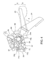
- Figure 4 is a simplified, enlarged bottom plan view of the main parts of the bicycle control device in an operation start position and a neutral position;
- Figure 5 is a simplified, enlarged bottom plan view, similar to Figure 4 , illustrating a second operating member in an intermediate position during an upshift operation;
- Figure 6 is a simplified, enlarged bottom plan view, similar to Figure 4 , illustrating the second operating member at the end of an upshift operation;
- Figure 7 is a simplified, enlarged bottom plan view, similar to Figure 4 , illustrating a first operating member being operated in a first direction in order to downshift;
- Figure 8 is a simplified, enlarged bottom plan view, similar to Figure 4 , illustrating the first operating member being operated in a second direction to switch a suspension operating state;
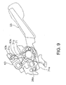
- Figure 9 is a simplified, enlarged bottom plan view, similar to Figure 4 , illustrating a locked state obtained by performing a suspension operating state switching operation;
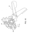
- Figure 10 is a simplified, enlarged bottom plan view, similar to Figure 4 , illustrating a situation in which the first operating member is returned to the neutral position after the locked state has obtained by performing a suspension operating state switching operation;
- Figure 11 shows an alternative example of a first operating member.
- Figure 12 shows an alternative example of a second operating member.
- the bicycle 1 basically includes a frame 2 having a suspension fork 3 and a handlebar 4 fixed to an upper part of the suspension fork 3.
- a front gear shifter device 15 is mounted to the handlebar 4 for operating a front derailleur 17, which is mounted to an intermediate section of the frame 2.
- the front gear shifter device 15 is an example of a bicycle control device for the bicycle 1 that operates the front derailleur 17 and the suspension fork 3.
- the front derailleur 17 is an example of a gear changing device that constitutes a first component part.
- the suspension fork 3 is an example of a suspension device that constitutes a second component part.
- the suspension fork 3 can be switched between a locked (off) state in which the suspension does not operate and an operational (on) state in which the suspension does operate.
- the suspension fork 3 is connected to the front gear shifter device 15 by with a state switching cable 10.
- a rear derailleur 18 is mounted to a rear end section of the frame 2.
- the front derailleur 17 is arranged, for example, on a bottom portion of a seat tube 2b of the frame 2.
- the front derailleur 17 is configured to guide a chain 9 onto any one of the sprockets of a front sprocket cluster 19a having, for example, three sprockets.
- the rear derailleur 18 is arranged, for example, on a rear end portion of a chain stay 2c of the frame 2.
- the rear derailleur 18 is configured to guide the chain 9 onto any one of the sprockets of a rear sprocket cluster 19b having, for example, nine sprockets.
- the front derailleur 17 is connected to the front derailleur operating unit 15 with a front shift cable 13 and the rear derailleur 18 is connected to a rear gear shifter device 16 with a rear shift cable 14. Therefore, the front derailleur 17 has three shift positions and the rear derailleur 18 has nine shift positions.
- the number of shift positions in the front can be two or three and the number of shift positions in the rear is not limited to nine.
- the front gear shifter device 15 is arranged on the handlebar 4 closely adjacent to a brake lever 12 on the inward side of the brake lever 12, and the rear gear shifter device 16 is arranged on the handlebar 4 closely adjacent to a brake lever 11 on the inward side of the brake lever 11.
- the front gear shifter device 15 is configured such that it can shift the front derailleur 17 among three shift positions and such that it can switch the operating state of the suspension fork 3 between an on-state and an off-state.
- the front gear shifter device 15 has a mounting part 20 configured to be mounted to the handlebar 4 on the inward side of the rear brake lever 12.
- Figure 2 is a perspective view from a position diagonally above the front gear shifter device 15. It is also acceptable for the mounting part 20 to be fixed integrally to a bracket of the rear brake lever 12.
- the front gear shifter device 15 includes a first actuating unit 21, a second actuating unit 22, a first operating member 23, a second operating member 24, a first movement transmitting mechanism 25 and second movement transmitting mechanism 26.
- the first actuating unit 21 is provided on the mounting part 20.
- the front gear shifter device 15 is configured to be connected to the front derailleur 17 by the front shift cable 13.
- the second actuating unit 22 is provided on the mounting part 20 and configured to be connected to the suspension fork 3 by the state switching cable 10.
- the first operating member 23 is movably provided on the mounting part 20 and configured to operate the first and second actuating units 21 and 22.
- the second operating member 24 is movably provided on the mounting part 20.
- the first movement transmitting mechanism 25 is arranged between the first operating member 23 and the first actuating unit 21.
- the first movement transmitting mechanism 25 is configured to transmit a movement of the first operating member 23 to the first actuating unit 21 in a first rotational direction.
- the second movement transmitting mechanism 26 is arranged between the first operating member 23 and the second actuating unit 22.
- the second movement transmitting mechanism 26 is configured to transmit a movement of the first operating member 23 to the second actuating unit 22 in a second rotational direction that is different from the first rotational direction.
- the mounting part 20 has a bracket 40 and a housing 42.
- the bracket 40 is made of, for example, sheet metal.
- the mounting part 20 is configured to be fastened to the handlebar 4 by tightening a bolt.
- the housing 42 is attached to the bracket 40 and configured to house the first and second actuating units 21 and 22.
- Figure 3 is a bottom plan view from underneath the front gear shifter device 15 with the housing 42 omitted.
- the bracket 40 has a first flat surface 40a, a second flat surface 40b and a non-circular opening 40c.
- the second flat surface 40b is located on a back side of the first flat surface 40a.
- the non-circular opening 40c receives a pivot shaft 46 in a non-rotatable fashion.
- the pivot shaft 46 is arranged to pass through the opening 40c of the bracket 40 and extend upward.
- the pivot shaft 46 is fastened with a fastening nut 41 installed on a tip (distal) end of the pivot shaft 46.
- the pivot shaft 46 serves to secure the second operating member 24 and other components (described later).
- the fastening nut 41 is a flanged cylindrical nut member having a hexagonal hole 41 a.
- a first outer casing stop 43 is provided for holding the outer casing 13b of the front shift cable 13 and a second outer casing stop 44 is provided for holding the outer casing 10b of the state switching cable 10.
- the first and second outer casing stops 43 and 44 are screwed onto the housing 42.
- the pivot shaft 46 has a larger-diameter flange section 46a, first pivot support section 46b, a second pivot support section 46c, a plurality of ribs 46d and an externally threaded section 46e.
- the larger-diameter flange section 46a is formed on a proximal end of the pivot shaft 46 and has a larger diameter than the first pivot support section 46b.
- the ribs 46d are formed on the second pivot support section 46c at equal intervals in the circumferential direction.
- the externally threaded section 46e is formed on a distal end of the pivot shaft 46.
- the fastening nut 41 is configured to screw onto the externally threaded section 46e.
- a first cable holding member 32 (described later) and a first movement transmitting arm 70 of the first movement transmitting mechanism 25 are pivotally mounted on the second pivot support section 46c with a bushing 52 disposed in-between.
- the second pivot support section 46c is also non-rotatably connected to the bracket 40 by the ribs 46d.
- a second cable holding member 36 (described later) is pivotally mounted on the first pivot support section 46b.
- the first actuating unit 21 includes the first cable holding member 32 (exemplifying a first actuating member) and a first positioning mechanism 34.
- the first cable holding member 32 is mounted to the mounting part 20 such that it can move in both a cable pulling direction and a cable releasing direction of an inner cable 13a of the front shift cable 13.
- the first positioning mechanism 34 is configured to selectively position the first cable holding member 32 in any one of a plurality of (e.g., three) actuation positions corresponding to a plurality of (e.g., three) shift positions of the front derailleur 17.
- the second actuating unit 22 comprises the second cable holding member 36 (exemplifying a second actuating member) and a second positioning mechanism 38.
- the second cable holding member 36 is formed integrally with the second movement transmitting mechanism 26.
- the second cable holding member 36 is mounted to the mounting part 20 such that it can move in both a cable pulling direction and the state switching cable 10.
- the second positioning mechanism 38 is configured to selectively position the second cable holding member 36 in any one of a plurality of (e.g., two) actuation positions corresponding to a plurality of (e.g., two) state positions of the suspension fork 3.
- the second cable holding member 36 and the second movement transmitting mechanism 26 are formed as a one-piece integral unit, it is also acceptable to form the same as separate members.
- the first cable holding member 32 is arranged such that it can move in a plane parallel to the first flat surface 40a of the bracket 40. More specifically, the first cable holding member 32 is mounted to the pivot shaft 46 with the bushing 52 such that it can move (pivot) freely in a cable retracting direction (cable pulling direction) and a cable release direction of the front shift cable 13.
- An inner cable holding section 32a is provided on an external circumferential surface of the first cable holding member 32 for engaging a cable nipple fixed to a tip end of the inner cable 13a of the front shift cable 13 ( Figure 2 ).
- a cable winding groove 32b is also provided on an external circumferential surface of the first cable holding member 32 for winding in the inner cable 13a on an external circumferential surface of the first cable holding member 32.
- the first cable holding member 32 is spring loaded in the cable release direction (clockwise in Figure 3 ) by a spring member 50 (e.g., a torsional coil spring). One end of the spring member 50 engages with the first cable holding member 32 and the other end engages with the bracket 40.
- An engaging protrusion 32c is formed on an upper surface of the first cable holding member 32 for causing a positioning member 54 of the first positioning mechanism 34 to rotate together with the first cable holding member 32.
- the first positioning mechanism 34 includes the positioning member 54 and a positioning pawl 55.
- the positioning pawl 55 has an actuating projection 55a, a stop member or tooth 56 and an over rotation preventing member or tooth 57.
- the positioning member 54 has, for example, three positioning teeth 62 and three winding teeth 64.
- the positioning member 54 is configured to move together with the first cable holding member 32.
- the stop tooth 56 is configured to move in a plane parallel to the first flat surface 40a between an engaging position in which it engages with the positioning teeth 62 and a release position in which it does not engage with the positioning teeth 62.
- the over rotation preventing member or tooth 57 is configured to move in a plane parallel to the first flat surface 40a between a contact position where it engages with the positioning teeth 62 at a different position than the stop tooth 56 and a disengaged position where it does not engage with the positioning teeth.
- the first positioning mechanism 34 also has a winding pawl 59 and a holding plate 61.
- the winding pawl 59 is configured to move between a winding position where it engages with the winding teeth 64 and a release position where it separates from the winding teeth 64.
- the holding plate 61 is mounted non-rotatably to the pivot shaft 46.
- the positioning member 54 has an engaging hole 54a configured to engage with the engaging protrusion 32c of the first cable holding member 32 such that the positioning member 54 moves integrally (as a unit) with the first cable holding member 32.
- the number of positioning teeth 62 and winding teeth 64 corresponds to the number of shift positions of the front derailleur 17.
- the teeth 62 and 64 are protrude radially outward from an external circumferential surface of the positioning member 54.
- the positioning member 54 is spring loaded in the cable release direction (clockwise in Figure 3 ) by the spring member 50.
- the size of the spaces between the positioning teeth 62 and the winding teeth 64 is determined based on the amount of cable movement required to achieve the shift positions of the front derailleur 17.
- the stop tooth 56 and the over rotation preventing tooth 57 are formed as integral portions of the positioning pawl 55 that is attached in a freely rockable manner to a rocking shaft 65.
- the rocking shaft 65 is arranged to protrude from the first flat surface 40a of the bracket 40.
- the positioning pawl 55 is spring loaded by a spring member 58 (e.g., a torsional coil spring) in the counterclockwise direction of Figure 3 such that the stop tooth 56 is arranged in the engaging position.
- the actuating projection 55a protrudes radially outward from an external circumferential surface of the positioning pawl 55. A distal end portion of the actuating projection 55a engages with a second movement transmitting protrusion 70c that has been formed by bending a distal end of the first movement transmitting arm 70 of the first movement transmitting mechanism 25.
- the stop tooth 56 is configured to contact the positioning teeth 62 so as to stop rotation of the positioning member 54 (which is spring loaded in the clockwise direction of Figure 3 ) in the cable release direction.
- the over rotation preventing tooth 57 moves to the contact position, it contacts a positioning tooth 62b located one tooth downstream in the release direction from the positioning tooth 62a that the stop tooth 56 was contacting, thereby preventing the positioning member 54 from continuing to rotate in the cable release direction after the positioning pawl separates from the positioning tooth 62a.
- the stop tooth 56 is arranged in a position located beyond the positioning tooth 62a that it was originally engaged with.
- the winding pawl 59 is attached in a freely rockable manner to a rocking shaft 66 arranged protruding from the second operating member 24.
- the winding pawl 59 is spring loaded in the counterclockwise direction of Figure 3 by a spring member 67 (e.g., a torsional coil spring) such that the winding pawl 59 is arranged in the winding position.
- a spring member 67 e.g., a torsional coil spring
- the holding plate 61 is non-rotatably connected to the pivot shaft 46 by engaging with the ribs 46d of the second pivot support section 46c of the pivot shaft 46.
- a contact part 61 a protrudes toward the winding pawl 59 is provided on the holding plate 61.
- the second cable holding member 36 is arranged such that it can move in a plane parallel to the second flat surface 40b of the bracket 40. More specifically, the second cable holding member 36 is attached to the pivot shaft 46 such that it can move (pivot) freely in both a cable pulling direction and a cable releasing direction of the state switching cable 10.
- An inner cable holding section 36a is provided on an external circumferential surface of the second cable holding member 36 for engaging a cable nipple fixed to a tip end of the inner cable 10a of the state switching cable 10 ( Figure 2 ).
- a cable winding groove 36b is also provided on the external circumferential surface of the second cable holding member 36 for winding in the inner cable 10a on the external circumferential surface of the second cable holding member 36.
- the second cable holding member 36 is spring loaded in the cable release direction (clockwise in Figure 3 ) by a spring member 51 (e.g., a coil spring).
- a spring member 51 e.g., a coil spring.
- One end of the spring member 51 engages with the second movement transmitting arm 71 and the other end engages with the bracket 40.
- the second positioning mechanism 38 is configured such that the second cable holding member 36 moves alternately between two positions, i.e., a release position (exemplifying a third actuation position as illustrated in Figure 4 ) and a pulling position (exemplifying a fourth actuation position as illustrated in Figure 10 ), in response to a rocking movement of the first operating member 23 in the counterclockwise direction.
- the second positioning mechanism 38 has a lock member 63 that is attached to a rocking shaft 68 in a freely rockable manner.
- the rocking shaft 68 is provided in an upright fashion on the second flat surface 40b of the bracket 40.
- the lock member 63 is spring loaded in the clockwise direction of Figure 3 by a spring member 72 (e.g., a torsional coil spring).
- the lock member 63 is configured to be moved alternately between a first holding position shown in Figure 4 and a second holding position shown in Figure 10 by the second movement transmitting mechanism 26.
- the second holding position is located counterclockwise from the first holding position when viewed as shown in Figure 4 .
- the rocking movement of the lock member 63 is restricted by a stopper (not shown) such that the lock member 63 will not turn beyond the first holding position in the clockwise direction.
- a curved cam groove 63a configured to engage with the second movement transmitting mechanism 26 is formed in a portion of the lock member 63 located between a distal end of the lock member 63 and the rocking axis of the same (i.e., toward the rightward end in Figure 3 ).
- An engaging pin 71c of the second movement transmitting arm 71 (described later) engages with the cam groove 63a.
- the first operating member 3 is a lever member that has a release lever function for a typical gear changing device.
- the first operating member 23 also has a state switching function for switching an operating state of the suspension fork. As shown in Figure 3 , the first operating member 23 is arranged such that it can move in a plane parallel to the second flat surface 40b of the bracket 40.
- the first operating member 23 is arranged on the second flat surface 40b side of the bracket 40 and supported in a freely rockable manner on the first pivot support section 46b of the pivot shaft 46.
- the first operating member 23 is arranged such that it can pivot freely in the clockwise direction of Figure 4 , i.e., the direction indicated with the arrow B in Figure 4 (exemplifies a first rotational direction), and the counterclockwise direction of Figure 4 , i.e., the direction indicated with the arrow C in Figure 4 (exemplifies a second rotational direction), from the neutral position shown in Figure 4 .
- the first operating member 23 is spring loaded toward the neutral position by a spring member 60 (e.g., a coil spring).
- the first operating member 23 has a mounting hole 23b and a sheet metal lever section 23a that extends in two substantially opposite radial directions from the mounting hole 23b.
- a first movement transmitting pin 25a constitutes part of the first movement transmitting mechanism 25.
- the first movement transmitting pin 25a is provided in an upright fashion on a first surface 23c located near the mounting hole 23b.
- the second movement transmitting pint 26a constitutes part of the second movement transmitting mechanism 26.
- the second movement transmitting pint 26a is provided in an upright fashion on a second surface 23d located on the flip side of the first operating member 23 as the first surface 23c.
- the first movement transmitting pin 25a is arranged to pass through a circular arc-shaped opening 40d formed in the bracket 40.
- the circular arc shape of the opening 40 is arranged to be coaxial with respect to the pivot axis.
- An operating section 23e is provided on a distal end of the first operating member 23.
- the second operating member 24 is a lever member that has a cable retraction (wind-in) lever function for a typical gear changing device.
- the second operating member 24 is mounted on the fastening nut 41 such that it can pivot freely between an operating start position shown in Figure 4 and an operation end position reached by pivoting counterclockwise (in Figure 4 ) from the operating start position.
- the second operating member 24 is spring loaded toward the operation start position by a spring member 75 (e.g., a spiral spring).
- An operating section 24a is provided on a first end of the second operating member 24.
- the rocking shaft 66 that supports the winding pawl 59 is provided in an upright fashion on the operating section 24a.
- the first movement transmitting mechanism 25 has the first movement transmitting pin 25a (exemplifying a first protruding part) and a first movement transmitting arm 70 (exemplifying a first movement transmitting member) arranged between the spring member 50 and the bracket 40.
- the first movement transmitting pint 25a is provided in an upright fashion on the first operating member 23 as mentioned previously.
- the first movement transmitting pint 25a is arranged and configured to pass through the opening 40d of the bracket 40 and extend to a position where it can contact the first movement transmitting arm 70.
- the first movement transmitting arm 70 is configured to rock in response to a rocking movement of the first operating member 23 in the clockwise direction of Figure 4 (first direction).
- the rocking movement of the movement transmitting arm 70 is transmitted to the positioning pawl 55 such that the movement of the first operating member 23 causes the first operating unit 21 to operate.
- the first movement transmitting arm 70 is mounted on the pivot shaft 46 with the bushing 52.
- the first movement transmitting arm 70 has an arm section 70a that extends radially outward from the rocking center thereof.
- the first movement transmitting arm 70 also has a first movement transmitting protrusion 70b (exemplifying a first engaging part) that is arranged to be spaced apart from the arm section 70a.
- the first movement transmitting protrusion 70b protrudes in a radial direction for engaging the first movement transmitting pin 25a.
- the first movement transmitting arm 70 is spring loaded in the counterclockwise direction of Figure 3 by a spring member 69 (e.g., a coil spring).
- the first movement transmitting arm 70 also has a second movement transmitting protrusion 70c formed by bending a distal end of the arm section 70a toward the positioning pawl 55. As described previously, the second movement transmitting protrusion 70c contacts the actuating projection 55a of the positioning pawl 55.
- the second movement transmitting mechanism 26 has a second movement transmitting pin 26a (exemplifying a second protruding part) and the second movement transmitting arm 71 (exemplifying a second movement transmitting member) that is formed as an integral unit with the second cable holding member 36.
- the second movement transmitting pin 26a is provided in an upright fashion on an end portion of the lever section 23a of the first operating member 23 that is opposite the end on which the operating section 23e is provided.
- the second movement transmitting pin 26a is configured to extend to a position where it can contact the second movement transmitting arm 71.
- the second movement transmitting arm 71 is configured to rock in response to a rocking movement of the first operating member 23 in the counterclockwise direction of Figure 4 (second direction). This rocking movement causes the lock member 63 to operate and actuate the second actuating unit 22.
- the second movement transmitting arm 71 is mounted on the first pivot support section 46a of the pivot shaft 46 and has a first arm section 71a that extends radially outward from the pivot center and a second arm section 71 b that extends in a different radial direction so as to be separated from the first arm section 71a in a circumferential direction.
- An engaging part 71d (exemplifying a second engaging part) is provided on a distal end of the first arm section 71a such that it can contact the second movement transmitting pin 26a.
- An engaging pin 71c is provided in an upright fashion on a distal end of the second arm section 71b to protrude toward the lock member 63.
- the engaging pin 71 c engages with the cam groove 63a and with an external surface in the vicinity of the distal end of the lock member 63 (indicated with bold solid line in Figure 4 ).
- the rocking movement of the second movement transmitting arm 71 causes the engaging pin 71c to move in the first direction (clockwise direction) along the external surface and the cam groove 63a of the lock member 63, thereby causing the lock member 63 to move the second cable holding member 36 formed as an integral part of the second movement transmitting arm 71 alternately between a release position and a lock position.
- the rear gear shifter device 16 has the same structure as the front gear shifter device 15 and is arranged on the inward side of the front brake lever 11 to as to be in a mirror image relationship with respect to the front gear shifter device 15.
- Figure 4 shows a state in which neither the first operating member 23 nor the second operating member 24 has been operated.
- the first operating member 23 is arranged in the neutral position and the second operating member 24 is arranged in the operation start position.
- the front derailleur 17 is in the low position, i.e., the position corresponding to the sprocket having the smallest tooth count, and the first cable holding member 32 is in the first actuation position.
- the subsequent Figures 5 to 10 show the front gear shifter device 15 as viewed from below. Different types of lines are used in these figures to make it easier to identify the parts of the device, but the line types themselves carry no particular meaning.
- the stop tooth 56 of the positioning pawl 55 is pressed by the positioning tooth 62a such that the positioning pawl 55 rocks in the clockwise direction.
- the second operating member 24 returns to the operation start position as shown in Figure 6 due to the spring load of the spring member 75 and the positioning member 54 is positioned due to the engagement of the stop tooth 56 with the positioning teeth 62a.
- the winding pawl 59 is arranged in a released position where it is separated from the winding teeth 64 by the contact part 61 a of the holding plate 61. In this state, the first cable holding member 32 is positioned in the second actuation position.
- the first operating member 23 is moved clockwise, i.e., in the first direction (direction indicated with the arrow B in Figure 6 )
- the first movement transmitting pin 25a presses against the first movement transmitting protrusion 70b of the first movement transmitting arm 70 and pivots the first movement transmitting arm 70 clockwise.
- the second movement transmitting protrusion formed on a distal end of the arm section 70a of the first movement transmitting arm 70 engages with the actuating projection 55a and moves the positioning pawl 55 in the clockwise direction.
- the positioning pawl 55 pivots clockwise, the stop tooth 56 separates from the positioning tooth 62a and the positioning member 54 rotates clockwise together with the first cable holding member 32 in the cable release direction.
- the over rotation preventing tooth 57 of the positioning pawl 55 contacts the positioning tooth 62b located one tooth away from the positioning tooth 62a and the positioning member 54 stops rotating.
- the rider releases the first operating member 23
- the first operating member 23 returns to the neutral position as shown in Figure 4 due to the spring force of the spring member 60.
- the positioning pawl 55 then rotates counterclockwise due to the spring member 58 and the over rotation preventing tooth 57 separates from the positioning tooth 62b, causing the positioning member 54 to rotate clockwise again.
- the stop tooth 56 contacts the positioning teeth 62 and causes the positioning member 54 and the first cable holding member 32 to be positioned (i.e., held in a position corresponding to the low gear).
- the inner cable 13a of the shift cable 13 is released by such an amount that the front derailleur 17 moves to the low position.
- the second movement transmitting arm 71 separates from the second movement transmitting pin 26a of the first operating member 23, the second movement transmitting mechanism 26 does not move.
- the engaging pin 71c reaches an end portion of the cam groove 63a and engages with the cam groove 63a so as to enter the cam groove 63a.
- the cam groove 63a has a stopping portion 63b where it bends approximately 90 degrees such that the engaging pin 71c can be stopped.
- the lock member 63 pivots clockwise due to the spring force of the spring member 72 until, as shown in Figure 9 , the engaging pin 71c is stopped by the stopping portion 63b such that the lock member 63 becomes held in the second holding position.
- the second movement transmitting arm 71 is thus positioned by the lock member 63.
- the second cable holding member 36 is positioned in the lock position.
- the state switching cable 10 causes the suspension fork 3 to be in a locked state in which it does not produce a suspension effect. If the rider releases the first operating member 23 while the lock member 63 is positioned in the second holding position, then the first operating member 23 will return to the neutral position due to the spring force of the spring member 60. This situation is illustrated in Figure 10 . In the state shown in Figure 10 , the second movement transmitting pin 26a is separated from the first arm section 71a of the second movement transmitting arm 71.
- the operation is simple because the suspension fork 3 can be switched alternately between a locked state and a released state by operating the first operating member 23 in the same manner, i.e., by pivoting the first operating member 23 in the second direction.
- two component parts i.e., the front derailleur 17 and the suspension fork 3
- two component parts 17 and 3 can be operated easily with a single first operating member 23.
- two component parts that require positioning e.g., a gear changing device (e.g., derailleur 17 or 18) and a suspension device, can be operated by operating a single first operating member 23 in different directions and the two component parts 17 and 3 can be operated easily without releasing one's hand from the first operating member 23.
- first and second movement transmitting mechanisms 25 and 26 are arranged between the first operating member 23 and the first and second actuating units 21 and 22, two component parts 17 and 3 can be actuated by moving the first operating member 23 in different directions.
- “between” does not mean spatially between but, rather, it means “between” in the sense of an intermediate position along a power transmission path.
- the first and second movement transmission mechanisms 25 and 26 each exists along the power transmission path through which force is transmitted from the first operating member 23 to the first and second actuating units 21 and 22.
- first operating member 23 Since the first operating member 23 is arranged sandwiched between the first and second movement transmitting mechanisms 25 and 26, movements of the first operating member 23 in the first and second directions can easily be transmitted to the first and second actuating units 21 and 22.
- first and second movement directions of the first operating member are opposite directions within the same plane
- the present invention is not limited to such an arrangement.
- a front derailleur 17 is presented as an example of a first component part and a suspension fork 3 is presented as an example of a second component
- the first and second component parts can be any type of component part that can be operated on a bicycle.
- the first component part can be a front derailleur and the second component part a rear derailleur such that both derailleurs are operated with the first operating member.
- the first component part can be a brake device and the second component part a suspension fork such that a brake device and a suspension fork are controlled with the first operating member.
- the bicycle control device is for operating an external gear changing device having a front derailleur and a rear derailleur
- the present invention can also be applied to a bicycle control device for an internal gear changing device having an internally geared hub.
- the mounting part 20 of the front gear shifter device 15 and the rear brake lever 11 are separate entities, it is acceptable for the mounting part to be fixed integrally to a brake lever bracket.
- a front gear shifter device 15 of a front derailleur 17 can also be employed to switch the operating state of a rear suspension in a bicycle equipped with a rear suspension for a rear wheel.
- a first operating member of a rear gear shifter device 16 can be configured to operate in a first direction and a second direction so as to actuate both a rear derailleur and a rear suspension (i.e., two component parts).
- the present invention is explained using bicycle components that are operated using a cable, the present invention is not limited to such components.
- the invention can also be applied to an electric powered gear changing device and an electric powered suspension device configured to be operated using an electric switch.
- Figure 11 shows a first operating member 123 for shifting gears.
- the first operating member 123 has a pivot support section 123a that is pivotally mounted to a pivot shaft 130 mounted to a mounting part 120 configured to be mounted to a bicycle, a switch actuating section 123b that extends toward a first end from the pivot support section 123a, and an operating section 123c that extends toward a second end from the pivot support section 123a.
- the first operating member 123 is spring loaded toward a neutral position by a pair of spring members 150.
- Electric switches 125 and 126 are provided in the mounting part 120 on both sides of the switch actuating section 123b.
- the electric switch 125 is for shifting the gear changing device in one direction (e.g., upshifting), and the electric switch 126 is for switching the operating state of a suspension device.
- Figure 12 shows a second operating member 124 for shifting gears.
- the second operating member 124 is pivotally mounted on the pivot shaft 130 and arranged to be separated from the first operating member 123 along the axial direction of the pivot shaft 130.
- the second operating member 124 has a pivot support section 124a that is pivotally mounted to a pivot shaft 130, a switch actuating section 124b that extends toward a first end from the pivot support section 124a, and an operating section 124c that extends toward a second end from the pivot support section 124a.
- the second operating member 124 is spring loaded in the counterclockwise direction of Figure 11 by a spring member 151.
- An electric switch 127 (e.g., a tact switch) is provided in the mounting part 120 on one side of the switch actuating section 124b.
- the electric switch 127 is a switch for shifting the gear changing device in the other direction (e.g., downshifting).
Claims (8)
- Fahrradbetriebssystem, umfassend:eine Gangschalteinrichtung (17), konfiguriert um an einem Fahrrad montiert zu werden;eine Federungseinrichtung, konfiguriert um an einem Fahrrad montiert zu werden; undeine Fahrradsteuereinrichtung (15) zum Betreiben oder Bedienen eines ersten Komponentenparts (17), welches die Gangschalteinrichtung ist, und eines zweiten Komponentenparts (3), welches die Federungseinrichtung eines Fahrrades ist, wobei die Fahrradsteuereinrichtung umfasst:einen Montagepart (20), konfiguriert um an dem Fahrrad montiert zu werden; eine erste Betätigungseinheit (21), angeordnet an dem Montagepart (20) und enthaltend ein erstes Komponentenverbindungs- oder -anschlusselement, welches konfiguriert ist um verbunden oder angeschlossen zu werden bezüglich dem ersten Komponentenpart, wobei die erste Betätigungseinheit (21) wirkgekoppelt ist bezüglich der Gangschalteinrichtung zum Verändern von Gangschaltpositionen oder -einstellungen;eine zweite Betätigungseinheit (22), angeordnet an dem Montagepart (20) und enthaltend ein zweites Komponentenverbindungs- oder -anschlusselement, welches konfiguriert ist um verbunden oder angeschlossen zu werden bezüglich dem zweiten Komponentenpart, wobei die zweite Betätigungseinheit (22) wirkgekoppelt ist bezüglich der Federungseinrichtung zum Verändern von Federungszuständen;ein erstes Betriebs- oder Bedienelement (23), beweglich gekoppelt zwischen dem Montagepart (20) und wirkgekoppelt bezüglich den ersten und zweiten Betätigungseinheiten (21, 22), und zwar ansprechend auf Bewegung des ersten Bedien- oder Betriebselementes (23) mit Bezug auf den Montagepart (20);einen ersten Bewegungsübertragungsmechanismus (25), angeordnet zwischen dem ersten Bedien- oder Betriebselement (23) und der ersten Betätigungseinheit (21), um eine Bewegung des ersten Bedien- oder Betriebselementes (23) in einer ersten Richtung zu der ersten Betätigungseinheit (21) zu übertragen;dadurch gekennzeichnet, dassein zweiter Bewegungsübertragungsmechanismus (26) angeordnet ist zwischen dem ersten Bedien- oder Betriebselement (23) und dem zweiten Betätigungselement (22), um eine Bewegung des ersten Betriebs- oder Bedienelementes (23) zu der zweiten Betätigungseinheit (22) in einer zweiten Richtung, welche unterschiedlich von der ersten Richtung ist zu übertragen,wobei die erste Betätigungseinheit (21) ein erstes Betätigungselement (32) enthält, konfiguriert um verbunden oder angeschlossen zu werden bezüglich dem ersten Komponentenpart (17), sowie einen ersten Positionierungsmechanismus (34) wirkgekoppelt bezüglich dem ersten Betätigungselement (32); unddie zweite Betätigungseinheit (22) über ein zweites Betätigungselement (36) verfügt, konfiguriert um verbunden oder angeschlossen zu werden bezüglich dem zweiten Komponentenpart (3) sowie über einen zweiten Positionierungsmechanismus (38) wirkgekoppelt bezüglich dem zweiten Betätigungselement (36).
- Fahrradbetriebs- oder -bediensystem gemäß Anspruch 1, bei welchem der erste Bewegungsübertragungsmechanismus (25) über ein erstes Bewegungsübertragungselement (70) verfügt, beweglich montiert mit Bezug auf den Montagepart (20), sowie über einen ersten vorspringenden Part (25a), bereitgestellt an einem Abschnitt des ersten Betriebs- oder Bedienelementes, wobei das erste bewegungsübertragende Element (70) in Eingriff vorliegt mit dem ersten vorspringenden Part (25a), und zwar ansprechend auf Bewegung des ersten Betriebs- oder Bedienelementes (23) in der ersten Richtung zum Bedienen oder Betreiben der ersten Betätigungseinheit; und bei welcher der zweite Bewegungsübertragungsmechanismus (26) über ein zweites Bewegungsübertragungselement (71) verfügt, beweglich montiert mit Bezug auf den Montagepart (20), sowie über einen zweiten vorspringenden Part (26a), bereitgestellt an einem Abschnitt des ersten Bedien- oder Betriebselementes, wobei das zweite bewegungsübertragende Element (71) in Eingriff mit dem zweiten vorspringenden Part (26a) ist, und zwar ansprechend auf Bewegung des ersten Bedien- oder Betriebselementes (23) in der zweiten Richtung zum Bedienen oder Betreiben der zweiten Betätigungseinheit.
- Fahrradbetriebs- oder -bediensystem gemäß einem der Ansprüche 1 bis 2, bei welchem die ersten und zweiten Richtungen entgegengesetzte Rotationsrichtungen sind.
- Fahrradbetriebs- oder -bediensystem gemäß einem der Ansprüche 1 bis 3, wobei die Fahrradsteuereinrichtung (15) ferner umfasst
ein zweites Betriebs- oder Bedienelement (24) beweglich gekoppelt mit dem Montagepart (20), derart, dass die Bewegung des zweiten Betriebs- oder Bedienelementes (24) mit Bezug auf den Montagepart (20) darin resultiert, dass sich das erste Betätigungselement (32) zu einer ersten Betätigungsposition von einer zweiten Betätigungsposition bewegt, wie bestimmt durch den ersten Positionierungsmechanismus (34), in welcher die zweiten Betätigungsposition unterschiedlich von der ersten Betätigungsposition ist. - Fahrradbetriebs- oder -bediensystem gemäß einem der Ansprüche 1 bis 4, bei welchem der Montagepart (20) ein Gehäuse enthält, aufweisend die ersten und zweiten Betätigungseinheiten (21; 22), und zwar in dem Gehäuse angeordnet.
- Fahrradbetriebs- oder -bediensystem gemäß einem der Ansprüche 1 bis 5, bei welchem das erste Bedien- oder Betriebselement (23) zwischen der ersten Betätigungseinheit (21) und der zweiten Betätigungseinheit (22) angeordnet ist.
- Fahrradbetriebs- oder -bediensystem gemäß einem der Ansprüche 1 bis 6, bei welchem die zweite Betätigungseinheit (24) konfiguriert ist zur abwechselnden Bewegung zwischen einer dritten Betätigungsposition und einer vierten Betätigungsposition, ansprechend auf eine Bewegung des ersten Bedien- oder Betriebselementes (23) in der zweiten Richtung.
- Fahrradbetriebs- oder -bediensystem gemäß einem der Ansprüche 1 bis 7, bei welchem die ersten Betätigungseinheit (21) ein erstes Betätigungselement enthält, konfiguriert um verbunden oder angeschlossen zu werden bezüglich der Gangschalteinrichtung, sowie einen ersten Positionierungsmechanismus, wirkgekoppelt bezüglich dem ersten Betätigungselement, wobei der erste Positionierungsmechanismus das erste Betätigungselement in einer unter einer Vielzahl von Betätigungspositionen hält und das erste Betätigungselement bewegt wird, ansprechend auf das erste Bedien- oder Betriebselement, welches in der ersten Richtung bewegt wird oder ist, zum Schalten der Gangschalteinrichtung; und bei welcher
die zweite Betätigungseinheit (22) über ein zweites Betätigungselement verfügt, konfiguriert um verbunden oder angeschlossen zu werden bezüglich der Federungseinrichtung, sowie über einen zweiten Positionierungsmechanismus, wirkgekoppelt bezüglich dem zweiten Betätigungselement, wobei der zweite Positionierungsmechanismus das zweite Betätigungselement in einer unter einer Vielzahl von Bedien- oder Betriebspositionen hält und das zweite Betätigungselement bewegt ist oder wird, ansprechend auf das erste Bedien- oder Betriebselement, welches bewegt ist oder wird in der zweiten Richtung, zur Veränderung eines Betriebs- oder Bedienzustandes der Federungseinrichtung.
Applications Claiming Priority (1)
| Application Number | Priority Date | Filing Date | Title |
|---|---|---|---|
| JP2007329131A JP2009149210A (ja) | 2007-12-20 | 2007-12-20 | 自転車用操作装置 |
Publications (3)
| Publication Number | Publication Date |
|---|---|
| EP2072390A2 EP2072390A2 (de) | 2009-06-24 |
| EP2072390A3 EP2072390A3 (de) | 2009-11-18 |
| EP2072390B1 true EP2072390B1 (de) | 2012-05-16 |
Family
ID=40456426
Family Applications (1)
| Application Number | Title | Priority Date | Filing Date |
|---|---|---|---|
| EP08166795A Active EP2072390B1 (de) | 2007-12-20 | 2008-10-16 | Betätigungsvorrichtung für ein Fahrrad |
Country Status (5)
| Country | Link |
|---|---|
| US (1) | US9944345B2 (de) |
| EP (1) | EP2072390B1 (de) |
| JP (1) | JP2009149210A (de) |
| CN (2) | CN101462576B (de) |
| TW (1) | TWI389814B (de) |
Families Citing this family (19)
| Publication number | Priority date | Publication date | Assignee | Title |
|---|---|---|---|---|
| US8375825B2 (en) * | 2009-10-08 | 2013-02-19 | Shimano Inc. | Bicycle operating device |
| US8978511B2 (en) * | 2010-11-09 | 2015-03-17 | Shimano Inc. | Position control mechanism |
| US8459144B2 (en) | 2011-09-29 | 2013-06-11 | Shimano Inc. | Bicycle shifter |
| US9327793B2 (en) | 2011-10-01 | 2016-05-03 | Shimano Inc. | Bicycle operating device |
| US9016164B2 (en) * | 2012-10-24 | 2015-04-28 | Shimano (Singapore) Pte. Ltd. | Bicycle control device |
| JP2014196060A (ja) * | 2013-03-29 | 2014-10-16 | 株式会社シマノ | 操作装置 |
| US8958962B2 (en) * | 2013-04-05 | 2015-02-17 | Shimano Inc. | Electric shift operating device |
| US9849932B2 (en) | 2014-04-29 | 2017-12-26 | Shimano Inc. | Bicycle component operating apparatus |
| US9637195B2 (en) | 2014-04-09 | 2017-05-02 | Shimano Inc. | Bicycle operating device |
| TWI634039B (zh) * | 2014-04-09 | 2018-09-01 | 島野股份有限公司 | 自行車操作裝置 |
| US9950764B2 (en) | 2014-04-09 | 2018-04-24 | Shimano Inc. | Bicycle operating device |
| US10023265B2 (en) * | 2014-09-02 | 2018-07-17 | Shimano Inc. | Bicycle control device |
| US9862451B2 (en) * | 2014-09-02 | 2018-01-09 | Shimano Inc. | Bicycle control device |
| US10131405B2 (en) * | 2015-04-13 | 2018-11-20 | Shimano Inc. | Bicycle control device for operating a bicycle component |
| US10046826B2 (en) * | 2015-08-27 | 2018-08-14 | Tektro Technology Corporation | Dual control lever and bicycle control assembly |
| US10473143B2 (en) * | 2017-08-27 | 2019-11-12 | Wolf Tooth Components, LLC | Control device |
| DE102019206835A1 (de) * | 2019-05-10 | 2020-11-12 | Sram Deutschland Gmbh | Fahrradbedienvorrichtung |
| US20220212748A1 (en) * | 2021-01-05 | 2022-07-07 | PNW Components LLC | Bicycle cockpit lever |
| US11787491B2 (en) | 2021-01-29 | 2023-10-17 | Wolf Tooth Components, LLC | Control device |
Family Cites Families (31)
| Publication number | Priority date | Publication date | Assignee | Title |
|---|---|---|---|---|
| US2534566A (en) * | 1947-08-19 | 1950-12-19 | Hercules Cycle And Motor Compa | Control for variable-speed gears on cycles |
| US2770980A (en) * | 1952-11-07 | 1956-11-20 | J A Phillips And Company Ltd | Variable speed gear control lever mechanism for bicycles and like vehicles |
| US3800618A (en) * | 1973-01-22 | 1974-04-02 | K Yoshigai | Brake operating device for bicycle |
| US3972247A (en) * | 1974-09-23 | 1976-08-03 | Armstrong Allen E | Bicycle shift mechanism |
| US4055093A (en) * | 1976-06-18 | 1977-10-25 | Amf Incorporated | 10-Speed bicycles |
| US4267742A (en) * | 1978-11-22 | 1981-05-19 | Cabeza Maximino R | Single lever control mechanism for bicycle front and rear derailleurs |
| US4785683A (en) * | 1987-07-09 | 1988-11-22 | Hayes Industrial Brake, Inc. | Hand operated brake actuator |
| US4850241A (en) * | 1987-12-22 | 1989-07-25 | Hayes Industrial Brake, Inc. | Cable tension equalizer for a lever operated brake actuator |
| US5241878A (en) * | 1988-11-29 | 1993-09-07 | Shimano, Inc. | Bicycle control device |
| JP2732116B2 (ja) * | 1988-11-29 | 1998-03-25 | 株式会社シマノ | 自転車用操作装置 |
| JP3245188B2 (ja) * | 1991-04-19 | 2002-01-07 | 株式会社シマノ | 自転車用変速操作装置 |
| SE500410C2 (sv) * | 1992-03-24 | 1994-06-20 | Ergotek I Smaland Ab | Påverkningsanordning för att medelst en hävarm manövrera ett föremål, exempelvis en broms |
| US5419216A (en) * | 1993-07-22 | 1995-05-30 | Huffy Corporation | Self-adjusting actuation mechanism |
| US5775168A (en) * | 1996-02-14 | 1998-07-07 | Shimano, Inc. | Combined brake and shifting device |
| TW446659B (en) * | 1996-06-18 | 2001-07-21 | Shimano Kk | Control device for a bicycle |
| US5896779A (en) * | 1997-08-01 | 1999-04-27 | Sunrise Medical Hhg Inc. | Dual mode brake actuator for walker |
| US5927441A (en) * | 1997-09-23 | 1999-07-27 | Luo; Chung-I | Braking device for trolley |
| US6032765A (en) * | 1999-08-09 | 2000-03-07 | Larmine Manufacturing Corp. | Brake control device for a wheeled walker |
| JP2001233188A (ja) * | 2000-02-25 | 2001-08-28 | Kuroishi Tekko Kk | 車両用パーキングブレーキ装置 |
| ITTO20010010A1 (it) * | 2001-01-11 | 2002-07-11 | Campagnolo Srl | Gruppo integrato di comando del cambio e del freno per una bicicletta. |
| US6734376B2 (en) * | 2002-06-19 | 2004-05-11 | Shimano Inc. | Electrical switch device for bicycle |
| US20040244526A1 (en) * | 2003-06-03 | 2004-12-09 | Jeff Jones | Bicycle handlebar |
| US7228756B2 (en) * | 2003-11-25 | 2007-06-12 | Shimano Inc. | Bicycle control device |
| US20050252330A1 (en) * | 2004-05-13 | 2005-11-17 | Denk Engineering Gmbh | Switch apparatus |
| US7802489B2 (en) * | 2005-06-01 | 2010-09-28 | Shimano Inc. | Bicycle control device |
| US9797434B2 (en) * | 2005-09-14 | 2017-10-24 | Shimano, Inc. | Bicycle shift operating device with a multi-direction operating member |
| JP4040057B2 (ja) * | 2005-09-14 | 2008-01-30 | 株式会社シマノ | 自転車用変速操作装置 |
| JP4040059B2 (ja) | 2005-11-30 | 2008-01-30 | 株式会社シマノ | 自転車用変速操作装置 |
| US7552935B2 (en) * | 2005-09-26 | 2009-06-30 | Specialized Bicycle Components, Inc. | Integrated bicycle shifting and suspension system |
| US20070287057A1 (en) | 2006-06-09 | 2007-12-13 | Elhamid Mahmoud H Abd | Method for making a hydrophilic corrosion resistant coating on low grade stainless steel/alloys for bipolar plates |
| ITMI20070239A1 (it) * | 2007-02-09 | 2008-08-10 | Campagnolo Srl | Dispositivo di comando per un deragliatore di bicicletta |
-
2007
- 2007-12-20 JP JP2007329131A patent/JP2009149210A/ja active Pending
-
2008
- 2008-07-07 TW TW097125568A patent/TWI389814B/zh active
- 2008-07-21 CN CN2008101316631A patent/CN101462576B/zh active Active
- 2008-07-21 CN CN2011100499162A patent/CN102133917B/zh active Active
- 2008-09-24 US US12/236,579 patent/US9944345B2/en active Active
- 2008-10-16 EP EP08166795A patent/EP2072390B1/de active Active
Also Published As
| Publication number | Publication date |
|---|---|
| CN102133917B (zh) | 2013-12-04 |
| JP2009149210A (ja) | 2009-07-09 |
| EP2072390A3 (de) | 2009-11-18 |
| CN101462576B (zh) | 2011-05-25 |
| CN101462576A (zh) | 2009-06-24 |
| TW200927583A (en) | 2009-07-01 |
| US20090158881A1 (en) | 2009-06-25 |
| EP2072390A2 (de) | 2009-06-24 |
| TWI389814B (zh) | 2013-03-21 |
| US9944345B2 (en) | 2018-04-17 |
| CN102133917A (zh) | 2011-07-27 |
Similar Documents
| Publication | Publication Date | Title |
|---|---|---|
| EP2072390B1 (de) | Betätigungsvorrichtung für ein Fahrrad | |
| US9199688B2 (en) | Bicycle control device | |
| EP1854713B1 (de) | Gangschaltung für ein Fahrrad | |
| US9132887B2 (en) | Bicycle operating device | |
| EP1728714B1 (de) | Fahrradsteuerungsvorrichtung | |
| EP1650121B2 (de) | Mechanismus zur Steuerung der Stellung einer Fahrradsteuerungsvorrichtung | |
| EP1997723B1 (de) | Betätigungsvorrichtung für ein Fahrrad | |
| US9327793B2 (en) | Bicycle operating device | |
| US8720301B2 (en) | Bicycle operating device | |
| EP1961652B1 (de) | Betätigungsvorrichtung für eine Fahrradgangschaltung | |
| US8746106B2 (en) | Bicycle operating device | |
| US9016163B2 (en) | Bicycle control device | |
| EP2189363B1 (de) | Kabelbetriebsmechanismus | |
| US8746105B2 (en) | Bicycle operating device | |
| US9381975B2 (en) | Bicycle shift operating device | |
| US8297146B2 (en) | Bicycle control device | |
| US9056648B2 (en) | Bicycle component positioning device | |
| US10259533B2 (en) | Bicycle operating device | |
| US8528442B2 (en) | Bicycle component positioning device | |
| US9156518B2 (en) | Cable operating mechanism | |
| US20080314185A1 (en) | Bicycle control device | |
| US10689060B2 (en) | Bicycle operating device | |
| US10207768B2 (en) | Bicycle operating device |
Legal Events
| Date | Code | Title | Description |
|---|---|---|---|
| PUAI | Public reference made under article 153(3) epc to a published international application that has entered the european phase |
Free format text: ORIGINAL CODE: 0009012 |
|
| AK | Designated contracting states |
Kind code of ref document: A2 Designated state(s): AT BE BG CH CY CZ DE DK EE ES FI FR GB GR HR HU IE IS IT LI LT LU LV MC MT NL NO PL PT RO SE SI SK TR |
|
| AX | Request for extension of the european patent |
Extension state: AL BA MK RS |
|
| PUAL | Search report despatched |
Free format text: ORIGINAL CODE: 0009013 |
|
| AK | Designated contracting states |
Kind code of ref document: A3 Designated state(s): AT BE BG CH CY CZ DE DK EE ES FI FR GB GR HR HU IE IS IT LI LT LU LV MC MT NL NO PL PT RO SE SI SK TR |
|
| AX | Request for extension of the european patent |
Extension state: AL BA MK RS |
|
| 17P | Request for examination filed |
Effective date: 20100518 |
|
| 17Q | First examination report despatched |
Effective date: 20100623 |
|
| AKX | Designation fees paid |
Designated state(s): DE FR IT |
|
| GRAP | Despatch of communication of intention to grant a patent |
Free format text: ORIGINAL CODE: EPIDOSNIGR1 |
|
| GRAS | Grant fee paid |
Free format text: ORIGINAL CODE: EPIDOSNIGR3 |
|
| GRAA | (expected) grant |
Free format text: ORIGINAL CODE: 0009210 |
|
| AK | Designated contracting states |
Kind code of ref document: B1 Designated state(s): DE FR IT |
|
| REG | Reference to a national code |
Ref country code: DE Ref legal event code: R082 Ref document number: 602008015556 Country of ref document: DE Representative=s name: 24IP LAW GROUP SONNENBERG FORTMANN, DE |
|
| REG | Reference to a national code |
Ref country code: DE Ref legal event code: R096 Ref document number: 602008015556 Country of ref document: DE Effective date: 20120719 |
|
| PLBE | No opposition filed within time limit |
Free format text: ORIGINAL CODE: 0009261 |
|
| STAA | Information on the status of an ep patent application or granted ep patent |
Free format text: STATUS: NO OPPOSITION FILED WITHIN TIME LIMIT |
|
| 26N | No opposition filed |
Effective date: 20130219 |
|
| REG | Reference to a national code |
Ref country code: DE Ref legal event code: R097 Ref document number: 602008015556 Country of ref document: DE Effective date: 20130219 |
|
| REG | Reference to a national code |
Ref country code: FR Ref legal event code: PLFP Year of fee payment: 8 |
|
| PGFP | Annual fee paid to national office [announced via postgrant information from national office to epo] |
Ref country code: FR Payment date: 20150908 Year of fee payment: 8 |
|
| PGFP | Annual fee paid to national office [announced via postgrant information from national office to epo] |
Ref country code: IT Payment date: 20161024 Year of fee payment: 9 |
|
| REG | Reference to a national code |
Ref country code: FR Ref legal event code: ST Effective date: 20170630 |
|
| PG25 | Lapsed in a contracting state [announced via postgrant information from national office to epo] |
Ref country code: FR Free format text: LAPSE BECAUSE OF NON-PAYMENT OF DUE FEES Effective date: 20161102 |
|
| PG25 | Lapsed in a contracting state [announced via postgrant information from national office to epo] |
Ref country code: IT Free format text: LAPSE BECAUSE OF NON-PAYMENT OF DUE FEES Effective date: 20171016 |
|
| REG | Reference to a national code |
Ref country code: DE Ref legal event code: R082 Ref document number: 602008015556 Country of ref document: DE Representative=s name: SONNENBERG HARRISON PARTNERSCHAFT MBB, DE Ref country code: DE Ref legal event code: R082 Ref document number: 602008015556 Country of ref document: DE Representative=s name: SONNENBERG HARRISON PARTNERSCHAFT MBB PATENT- , DE |
|
| P01 | Opt-out of the competence of the unified patent court (upc) registered |
Effective date: 20230424 |
|
| PGFP | Annual fee paid to national office [announced via postgrant information from national office to epo] |
Ref country code: DE Payment date: 20230830 Year of fee payment: 16 |