EP2071688B1 - Passage de câbles à travers un mur de bâtiment - Google Patents
Passage de câbles à travers un mur de bâtiment Download PDFInfo
- Publication number
- EP2071688B1 EP2071688B1 EP07024323A EP07024323A EP2071688B1 EP 2071688 B1 EP2071688 B1 EP 2071688B1 EP 07024323 A EP07024323 A EP 07024323A EP 07024323 A EP07024323 A EP 07024323A EP 2071688 B1 EP2071688 B1 EP 2071688B1
- Authority
- EP
- European Patent Office
- Prior art keywords
- grommet
- opening
- conduit
- duct
- jacket
- Prior art date
- Legal status (The legal status is an assumption and is not a legal conclusion. Google has not performed a legal analysis and makes no representation as to the accuracy of the status listed.)
- Active
Links
- 239000000945 filler Substances 0.000 claims abstract description 25
- 239000000126 substance Substances 0.000 claims abstract description 25
- 238000007789 sealing Methods 0.000 claims description 55
- 238000000034 method Methods 0.000 claims description 21
- 239000000463 material Substances 0.000 claims description 12
- 238000006243 chemical reaction Methods 0.000 claims description 6
- 229920001971 elastomer Polymers 0.000 claims description 6
- 239000000806 elastomer Substances 0.000 claims description 6
- XLYOFNOQVPJJNP-UHFFFAOYSA-N water Substances O XLYOFNOQVPJJNP-UHFFFAOYSA-N 0.000 claims description 4
- 230000009471 action Effects 0.000 claims description 2
- 229920005830 Polyurethane Foam Polymers 0.000 description 8
- 230000000694 effects Effects 0.000 description 5
- 238000002347 injection Methods 0.000 description 5
- 239000007924 injection Substances 0.000 description 5
- 239000004570 mortar (masonry) Substances 0.000 description 5
- 230000006835 compression Effects 0.000 description 4
- 238000007906 compression Methods 0.000 description 4
- 239000004744 fabric Substances 0.000 description 3
- 238000003780 insertion Methods 0.000 description 3
- 230000037431 insertion Effects 0.000 description 3
- 230000008569 process Effects 0.000 description 3
- 238000001035 drying Methods 0.000 description 2
- 230000009969 flowable effect Effects 0.000 description 2
- 238000010438 heat treatment Methods 0.000 description 2
- 239000007788 liquid Substances 0.000 description 2
- 238000004873 anchoring Methods 0.000 description 1
- 230000009286 beneficial effect Effects 0.000 description 1
- 230000008901 benefit Effects 0.000 description 1
- 239000007795 chemical reaction product Substances 0.000 description 1
- 239000011248 coating agent Substances 0.000 description 1
- 238000000576 coating method Methods 0.000 description 1
- 230000000295 complement effect Effects 0.000 description 1
- 239000000470 constituent Substances 0.000 description 1
- 230000006378 damage Effects 0.000 description 1
- 230000001419 dependent effect Effects 0.000 description 1
- 238000006073 displacement reaction Methods 0.000 description 1
- 239000013536 elastomeric material Substances 0.000 description 1
- 238000009434 installation Methods 0.000 description 1
- 230000007246 mechanism Effects 0.000 description 1
- 230000035699 permeability Effects 0.000 description 1
- 239000011496 polyurethane foam Substances 0.000 description 1
- 230000009467 reduction Effects 0.000 description 1
- 238000009416 shuttering Methods 0.000 description 1
- 239000007921 spray Substances 0.000 description 1
- 239000007858 starting material Substances 0.000 description 1
- 230000003068 static effect Effects 0.000 description 1
- 238000012876 topography Methods 0.000 description 1
Images


Classifications
-
- H—ELECTRICITY
- H02—GENERATION; CONVERSION OR DISTRIBUTION OF ELECTRIC POWER
- H02G—INSTALLATION OF ELECTRIC CABLES OR LINES, OR OF COMBINED OPTICAL AND ELECTRIC CABLES OR LINES
- H02G3/00—Installations of electric cables or lines or protective tubing therefor in or on buildings, equivalent structures or vehicles
- H02G3/22—Installations of cables or lines through walls, floors or ceilings, e.g. into buildings
-
- F—MECHANICAL ENGINEERING; LIGHTING; HEATING; WEAPONS; BLASTING
- F16—ENGINEERING ELEMENTS AND UNITS; GENERAL MEASURES FOR PRODUCING AND MAINTAINING EFFECTIVE FUNCTIONING OF MACHINES OR INSTALLATIONS; THERMAL INSULATION IN GENERAL
- F16L—PIPES; JOINTS OR FITTINGS FOR PIPES; SUPPORTS FOR PIPES, CABLES OR PROTECTIVE TUBING; MEANS FOR THERMAL INSULATION IN GENERAL
- F16L5/00—Devices for use where pipes, cables or protective tubing pass through walls or partitions
- F16L5/02—Sealing
Definitions
- This invention relates to the attachment of a cable feedthrough in a passage opening of a building wall.
- this is done, for example, by mortaring, wherein the passage opening in the building wall is connected to the performed line on both sides of the building wall and the volume surrounding the line is filled within the passage opening with a mortar. Due to the necessary shuttering and the long drying times of the mortar, this process is relatively expensive. Another disadvantage is the shrinkage of the mortar during the drying process.
- expansion mortar in which, however, the sufficient backfilling of the passage opening, especially in porous masonry, is not necessarily guaranteed, since the expansion mortar initially has a low viscosity and can penetrate uncontrollably into cavities of the building wall. An essential part of the material is then no longer available for backfilling the passage opening.
- the EP 1 101 993 A1 shows to seal a guided through a wall opening pipe a pipe enclosing support member on which a fabric bag is provided. This is introduced by an axial displacement of the support element along the tube in the wall opening and is held in the folded state on the support member. After the positioning of the support element, the fabric bag is supplied with sealing means by a channel provided in the support element, so that the fabric bag unfolds and rests against a soffit of the wall opening and against the pipe.
- This invention is based on the problem. Efficient and application-safe cable feedthroughs through openings in building walls.
- the invention solves the problem with a method for attaching a cable bushing in a passage opening of a building wall, in which a grommet enclosing the cable bushing, wherein a flexible jacket of the grommet within the passage opening is expanded by the action of a pressure of a flowable filler perpendicular to the direction of execution and the Fills filler in an expanded state, wherein the material of the shell is an elastomer, and with a grommet for this process with two in the passage direction spaced end pieces, each having an opening for the cable feedthrough, and with a connecting the end pieces, flexible sheath, with forms a volume for receiving the filler, the filling substance, wherein the filler is adapted to increase in the interior of the grommet through a chemical reaction their volume ßern and build up the pressure for expansion of the grommet, wherein the material of the shell is an elastomer.
- the basic idea of this invention is based on the use of a sleeve with a flexible jacket of an elastomeric material.
- This so-called grommet then encloses the cable bushing.
- Inside the sleeve is a flowable filling substance, by the pressure of the sleeve can be expanded after insertion into the passage opening of the building wall perpendicular to the direction of execution.
- the grommet expands to the extent of the cross-sectional area of the passage opening, so that the grommet is pressed in the passage opening.
- the attachment of the imple mentation sleeve within the passage opening takes place by static friction and / or positive engagement.
- the Filler hardens in the expanded state of the bushing, so that the fastening effect is permanently maintained.
- an elastomer is provided as material for the jacket of the sleeve, which allows a controlled expansion of the grommet at a certain pressure due to its elastic properties.
- the increasing expansion of the shell at an increasing pressure inside the sleeve leads to the desired compression in the passage opening. Due to the elastic elongation of the shell, this adapts to the topography of the inner surface of the passage opening and thus causes a positive connection between the inner surface and the grommet. In this case, cracks or cavities within the building wall are bridged by the jacket and a reduction of the fastening effect of the grommet due to excessive expansion of the filler in these cavities avoided.
- cable bushing is referred to below as an empty pipe for receiving a pipe section or a pipe section itself.
- These buildings are typically power lines. Water, gas, district heating or telecommunications lines.
- the bushing according to the invention has two end pieces and a sheath made of flexible material, which connects the end pieces and encloses the cable bushing.
- a sheath made of flexible material, which connects the end pieces and encloses the cable bushing.
- embodiments are included, in which the end pieces and the jacket are integral.
- the end pieces each have an opening, so that the cable feedthrough can be performed by the sleeve or can. It may be both the cable bushing firmly connected to the sleeve, and the cable feedthrough performed only when using the grommet through this and secured with a suitable fixture.
- the grommet in this invention is a volume for receiving the filler, which preferably increases its volume by a chemical reaction to build up the pressure necessary to expand the grommet.
- this pressure of the sleeve can also be supplied via an external device, for example a pump or press, or simply by manual actuation of the filling device.
- a 2-component material is used, which is injected after insertion of the grommet in the passage opening in the passage sleeve, such as PU foam.
- the injection of the 2-component material takes place through a further opening of a closure piece, namely a so-called injection opening.
- the injection opening may be designed for receiving a spray nozzle or cannula of a commercially available cartridge.
- it must be designed so that by the injected filler, a pressure build-up inside the grommet is possible.
- the components of the filling substance are already contained separately in the grommet and these are brought into contact with the passage opening after insertion of the grommet in order to initiate the chemical reaction causing the expansion ,
- the flexible jacket has a permeability to the filling substance above a certain threshold pressure.
- the pressure threshold is in an area whose lower limit is increasingly preferred at 5, 8, 11, 14 or 16 mbar and whose upper limit is increasingly preferably 50, 40, 30, 25 or 20 mbar.
- the leakage of the filler from a certain threshold pressure through the jacket can be achieved for example by a perforation of the shell, wherein the perforations open by the expansion of the shell during the expansion of the grommet and thus ensure the discharge of the filler.
- mechanisms are also conceivable for the discharge of the filling substance through the shell, which are based on the destruction, for example a tearing or dissolving, of constituents of the shell by the filling substance.
- expansion of the grommet results in compression, thereby securing the grommet in the passage opening in the wall.
- a sealing of the passage opening can be carried out through the grommet by this compression with a suitable surface finish in the interior of the passage opening. If appropriate, this sealing effect is markedly improved, particularly in the case of rough or porous surfaces or in the case of a wall structure with air inclusions, by the filling substance emerging from the jacket at a certain pressure threshold value.
- a seal on the exterior surface of the wall surrounding the passage opening is desirable, and the wall may be provided with an additional sealing coating.
- a sealing disc is provided with larger end pieces, in particular with a larger diameter than the passage opening, as compared to end pieces of larger design introduced into the passage opening.
- the passage opening in principle satisfies the fastening effect of the grommet inside the passage opening, although an additional sealing effect of the grommet, of course, can only be beneficial.
- the grommet In addition to the attachment of the cable bushing, the grommet must ensure the necessary for sealing on the outer wall surface contact pressure of the sealing washer.
- the sealing disk can, as already mentioned, coincide with a closure piece.
- a part of this component protrude as a "final piece” in the passage opening and another part of the same component as a “sealing disc” in front of it.
- the function of the end piece can also be ensured only by a fitting outside of the passage opening larger part:
- the sealing disc form an additional component to the second end piece and in particular after mounting the grommet to the sleeve are attached, are screwed about by a thread , The sealing washer and end piece can therefore coincide, but they do not have to.
- the sealing disc can be connected to the grommet by means of a holding device, then it can be retrofitted after the grommet has been fastened in the passage opening. Serves the larger end piece of the sealing of the outer wall, it can be temporarily pressed with a clamping device to be sealed to the wall surface until the filler is cured in the grommet and thus the grommet holds the necessary contact pressure for the seal upright.
- Another feature of the invention lies in the possibility that the two end pieces approach each other in the feedthrough direction when the grommet is expanded.
- the grommet closes at a certain time of the flexible jacket with the inner surface of the füröff voltage and thus establishes a mechanically strong connection of the sleeve with the building wall.
- this contact surface between the flexible shell and the inner surface of the passage opening increases and approach the end pieces further. Since now the grommet is already firmly anchored in the passage opening, the necessary contact pressure force is built on the sealing disk for sealing on the outer surface of the wall by the further approximation of the end caps
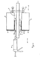
- FIG. 1 a jacket 6 and a closure piece 4 of the grommet are already inserted into a passage opening 2.
- Another end piece 5 which is also a sealing washer and larger in diameter than the passage opening 2, located on the outside 11 of the building wall 3.
- the line bushing 1 through the passage opening 2 is fixedly connected to the sealing washer 5 of the fürmenrngshülse.
- the opening 14 of the sealing washer 5 has a holding device for the cable bushing 1, to allow attachment of the grommet to the cable bushing 1 until shortly before installation.
- the conduit bushing 1 is a teaching tube for receiving a pipe section.
- the line bushing 1 may also be a line section, for example a power, water, gas, district heating or telecommunication line.
- the building wall 3 is coated on the outer side 11 with an outer seal 9, to which the sealing disk 5 is pressed in order to seal the passage opening 2 on the outer surface of the building wall 3 surrounding it.
- the necessary for the sealing on the outer seal 9 contact pressure of the sealing washer 5 is temporarily constructed with a clamping device 10.
- the tensioning device 10 is fastened to the cable bushing 1, so that the force required to build up the necessary contact pressure of the sealing disk 5 is transmitted by the cable bushing 1.
- the clamping device 10 is braced on the inside 12 of the building wall 3 against the wall surface, so that the cable feedthrough 1 and the sealing washer 5 are pulled in the direction of the inside 12 of the building wall 3.
- a 2-component PU foam is filled into the volume 8 of the grommet. This is done with a conventional cartridge 13 via the injection port 7 of the end piece 5. The introduced into the volume 8 PU foam begins to expand in the grommet and thus fills the volume 8. The further expansion of the PU foam causes a pressure increase inside the Bushing which leads to an expansion of the shell 6, whose material is an elastomer. As a result, the grommet is pressed in the interior of the passage opening 2 to the building wall 3 and secured in this. After curing of the PU foam in the grommet, the clamping device 10 can be removed from the line bushing 1 and the sealing disc 5 is held by the anchoring of the expanded shell 6 within the passage opening 2.
- the attachment according to the invention of the line bushing 1 is achieved in the passage opening 2.
- the sealing disc 5 seals the passage opening 2 by its pressure on the outer seal 9 of the building wall 3.
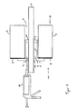
- the second embodiment in FIG. 2 differs by the sheath 6a from the FIG. 1 ,
- the coat 6a in FIG. 2 is complementary to the properties of the coat 6 in FIG. 1 provided with a perforation. This perforation allows the escape of the PU foam from the volume 8 of the grommet from a pressure threshold of 18 mbar.
- this exemplary embodiment of the feedthrough sleeve offers improved fastening and sealing of the cable feedthrough 1 in the passage opening 2 through the polyurethane foam between the casing 6a and the inner surface of the passage opening 2. This is especially true for a passage opening 2 with a passage rough or cracked inner surface of the passage opening 2, as well as in cavities within the building wall 3 advantageous.
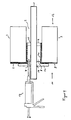
- FIG. 3 equals to FIG. 1 , in which case the tensioning device 10 for temporary generation of the contact pressure for the sealing disk 5 is dispensed with.
- the end pieces 4 and 5 approach - the sealing disc is also a final piece - in the expansion of the shell 6.
- a compression of a portion of the shell 6 takes place in the passage opening 2 in a first phase, whereby the grommet is fixed in the füröff opening 2.
- the necessary contact pressure for the sealing washer 5 is constructed for sealing on the outer seal 9 by the mutual approach of the end pieces 4 and 5.
- FIG. 4 an embodiment is shown with a variant of the sealing washer 5a, which has a taper, so that a part of the sealing disc seals on the outer seal 9 and the tapered part of the sealing washer 5a protrudes quasi as a final piece in the passage opening 2.
- the pressure necessary for pressing the sealing washer 5a is built up by the approach of the end piece 4 and the sealing washer 5a during the expansion of the sleeve, so that the clamping device 10 is not necessary for mounting the bushing.
- FIG. 5 shows a bushing with two end pieces 4c in a passage opening 2 for fixing a cable bushing 1, in which both end pieces 4, 5b were introduced into the passage opening 2.
- the sealing on the outer seal 9 of the building wall 3 takes place here with a separate sealing washer 16.
- This sealing washer 16 is fixed after the attachment of the grommet, so after expansion of the shell 6 by means of a holding device 17 on the end piece 5b
- the attachment takes place in this example a screw to build up the pressure necessary for the sealing pressure of the sealing disc 16.
- the cartridge 13 is already removed at this time.
Landscapes
- Engineering & Computer Science (AREA)
- General Engineering & Computer Science (AREA)
- Architecture (AREA)
- Civil Engineering (AREA)
- Structural Engineering (AREA)
- Mechanical Engineering (AREA)
- Installation Of Indoor Wiring (AREA)
- Details Of Indoor Wiring (AREA)
- Laying Of Electric Cables Or Lines Outside (AREA)
Claims (23)
- Procédé pour fixer un passage de conduite (1) dans une ouverture de passage (2) d'une paroi de bâtiment (3), dans lequel un manchon de passage entoure le passage de conduite (1),
une enveloppe (6, 6a) du manchon de passage étant expansée à l'intérieur de l'ouverture de passage (2) sous l'action de une pression d'une substance de remplissage fluide perpendiculairement au sens de passage et la substance de remplissage durcissant dans l'état expansé,
le matériau de l'enveloppe (6, 6a) étant un élastomère. - Procédé selon la revendication 1, dans lequel le manchon de passage présente deux pièces de fermeture (4, 5, 5a, 5b) espacées dans le sens de passage avec chaque fois une ouverture (14, 15) pour le passage de conduite (1) et l'enveloppe flexible relie les pièces de fermeture (4, 5, 5a, 5b).
- Procédé selon l'une des revendications précédentes, dans lequel la substance de remplissage augmente son volume à l'intérieur du manchon de passage sous l'effet d'une réaction chimique et établit la pression pour l'expansion du manchon de passage.
- Procédé selon l'une des revendications précédentes, dans lequel la substance de remplissage est un matériau d'expansion à deux composants.
- Procédé selon l'une des revendications précédentes, dans lequel le manchon de passage n'est rempli avec la substance de remplissage qu'à l'intérieur de l'ouverture de passage (2).
- Procédé selon l'une des revendications 2 à 5, dans lequel la substance de remplissage sort à travers l'enveloppe (6a) à partir d'une valeur seuil de pression définie.
- Procédé selon la revendication 6, dans lequel la valeur seuil de pression se situe entre 5 et 50 mbars.
- Procédé selon la revendication 6, également en liaison avec une autre des revendications précédentes, dans lequel l'enveloppe (6a) est perforée et les ouvertures de perforation permettent la sortie de la substance de remplissage de l'intérieur du manchon de passage à partir de la valeur seuil de pression.
- Procédé selon l'une des revendications précédentes, dans lequel le manchon de passage étanchéifie conjointement avec la substance de remplissage l'ouverture de passage (2) dans le sens axial.
- Procédé selon l'une des revendications 2 à 9, dans lequel une plate d'étanchéité (5, 5a, 16) est prévue, qui est supérieure à l'ouverture de passage (2) et avec laquelle l'ouverture de passage (2) est étanchéifiée sur une surface extérieure entourant l'ouverture de passage (2).
- Dispositif selon la revendication 10, dans lequel la plate d'étanchéité (5, 5a) est une pièce de fermeture.
- Procédé selon la revendication 10 ou 11, dans lequel les pièces de fermeture (4, 5, 5a, 5b, 16) reliées par l'enveloppe (6, 6a) se rapprochent les unes des autres lors de l'expansion du manchon de passage dans le sens de passage et la plate d'étanchéité (5, 5a, 16) est ainsi étirée sur la surface extérieure.
- Procédé selon la revendication 10 ou 11, dans lequel la plate d'étanchéité (5) est étirée avec un dispositif de tension (10) jusqu'au durcissement de la substance de remplissage sur la surface extérieure.
- Manchon de passage pour un procédé pour la fixation d'un passage de conduite (1) selon l'une des revendications 1-13 avec deux pièces de fermeture (4, 5, 5a, 5b) espacées dans le sens de passage, qui présentent chacune une ouverture (14, 15) pour le passage de conduite (1), et avec une enveloppe (6, 6a) flexible, reliant les pièces de fermeture (4, 5, 5a, 5b), qui forme avec les pièces de fermeture (4, 5, 5a, 5b) un volume (8) pour le logement de la substance de remplissage,
la substance de remplissage étant conçue pour augmenter son volume à l'intérieur du manchon de passage par une réaction chimique et établir la pression pour l'expansion du manchon de passage,
le matériau de l'enveloppe (6, 6a) étant un élastomère. - Manchon de passage selon la revendication 14 avec un dispositif de support pour le passage de conduite (1) sur une pièce de fermeture (4, 5, 5a, 5b).
- Manchon de passage selon la revendication 14, sur lequel le passage de conduite (1) est relié fixement à une pièce de fermeture (4, 5, 5a, 5b).
- Manchon de passage selon la revendication 15 ou 16, comprenant une plate d'étanchéité (5, 5a, 16) pour l'étanchéité sur une surface extérieure entourant l'ouverture de passage (2).
- Manchon de passage selon la revendication 17, sur lequel une pièce de fermeture (4, 5b) présente un dispositif de support pour la fixation de la plate d'étanchéité (16).
- Manchon de passage selon la revendication 17 ou 18, sur lequel la plate d'étanchéité (5, 5a) est une pièce de fermeture (5, 5a).
- Manchon de passage selon l'une des revendications 14-19, sur lequel le passage de conduite (1) est sélectionné dans le groupe comprenant la conduite électrique, la conduite d'eau, la conduite de gaz, la conduite de télécommunication et le tuyau vide pour le logement d'une telle conduite.
- Manchon de passage selon l'une des revendications 14-20, sur lequel l'enveloppe (6a) est perméable pour la substance de remplissage à partir d'une valeur seuil de pression comprise entre 5 et 50 mbars.
- Utilisation d'un manchon de passage selon l'une des revendications 14-21 pour la fixation d'un passage de conduite (1) dans une ouverture de passage (2) d'une paroi de bâtiment (3).
- Utilisation d'un manchon de passage selon la revendication 22 selon un procédé selon l'une des revendications 1-13.
Priority Applications (7)
| Application Number | Priority Date | Filing Date | Title |
|---|---|---|---|
| EP07024323A EP2071688B1 (fr) | 2007-12-14 | 2007-12-14 | Passage de câbles à travers un mur de bâtiment |
| DE200720018490 DE202007018490U1 (de) | 2007-12-14 | 2007-12-14 | Leitungsdurchführung durch eine Gebäudewand |
| EP10010530A EP2270942B1 (fr) | 2007-12-14 | 2007-12-14 | Méthode pour fixer un passage de câbles à travers un mur de bâtiment |
| AT07024323T ATE535747T1 (de) | 2007-12-14 | 2007-12-14 | Leitungsdurchführung durch eine gebäudewand |
| PL07024323T PL2071688T3 (pl) | 2007-12-14 | 2007-12-14 | Przepust przewodu przez ścianę budynku |
| PL10010530T PL2270942T3 (pl) | 2007-12-14 | 2007-12-14 | Sposób mocowania przepustu przewodowego przez ścianę budynku |
| PCT/EP2008/010608 WO2009077138A1 (fr) | 2007-12-14 | 2008-12-12 | Passage de conduites au travers d'un mur d'immeuble |
Applications Claiming Priority (1)
| Application Number | Priority Date | Filing Date | Title |
|---|---|---|---|
| EP07024323A EP2071688B1 (fr) | 2007-12-14 | 2007-12-14 | Passage de câbles à travers un mur de bâtiment |
Related Child Applications (1)
| Application Number | Title | Priority Date | Filing Date |
|---|---|---|---|
| EP10010530.3 Division-Into | 2010-09-24 |
Publications (2)
| Publication Number | Publication Date |
|---|---|
| EP2071688A1 EP2071688A1 (fr) | 2009-06-17 |
| EP2071688B1 true EP2071688B1 (fr) | 2011-11-30 |
Family
ID=39322732
Family Applications (2)
| Application Number | Title | Priority Date | Filing Date |
|---|---|---|---|
| EP10010530A Active EP2270942B1 (fr) | 2007-12-14 | 2007-12-14 | Méthode pour fixer un passage de câbles à travers un mur de bâtiment |
| EP07024323A Active EP2071688B1 (fr) | 2007-12-14 | 2007-12-14 | Passage de câbles à travers un mur de bâtiment |
Family Applications Before (1)
| Application Number | Title | Priority Date | Filing Date |
|---|---|---|---|
| EP10010530A Active EP2270942B1 (fr) | 2007-12-14 | 2007-12-14 | Méthode pour fixer un passage de câbles à travers un mur de bâtiment |
Country Status (4)
| Country | Link |
|---|---|
| EP (2) | EP2270942B1 (fr) |
| AT (1) | ATE535747T1 (fr) |
| PL (2) | PL2270942T3 (fr) |
| WO (1) | WO2009077138A1 (fr) |
Cited By (4)
| Publication number | Priority date | Publication date | Assignee | Title |
|---|---|---|---|---|
| CN102878354A (zh) * | 2012-10-10 | 2013-01-16 | 中国建筑第七工程局有限公司 | 一种柔性防水套管的制作方法 |
| DE202012011373U1 (de) | 2012-11-28 | 2014-03-05 | Doyma Gmbh & Co | Durchführungsvorrichtung für Leitungen, insbesondere Hauseinführung |
| DE202014005287U1 (de) | 2014-06-26 | 2015-10-05 | Doyma Gmbh & Co | Dichtmanschette für Leitungsdurchführungen mit einer Ankerfüllung |
| DE102016104129A1 (de) | 2016-03-07 | 2017-09-07 | Gabo Systemtechnik Gmbh | Vorrichtung und Verfahren zum Befestigen und Abdichten einer Leitungsdurchführung in einem Wanddurchgang einer Gebäudewand |
Families Citing this family (7)
| Publication number | Priority date | Publication date | Assignee | Title |
|---|---|---|---|---|
| AT12703U1 (de) * | 2011-10-27 | 2012-10-15 | Viterma Gmbh | Anordnung von durch löcher in fliesen oder sonstigen wandverkleidungen hindurch geführten rohren |
| EP2645507B1 (fr) | 2012-03-29 | 2014-05-14 | Hauff-Technik GmbH & Co. KG | Passage de conduite pour fixation dans une paroi de bâtiment |
| DE202012003184U1 (de) | 2012-03-29 | 2013-07-01 | Hauff-Technik Gmbh & Co. Kg | Leitungsdurchführung zur Befestigung in einer Gebäudewand |
| DE102014009319C5 (de) | 2014-06-27 | 2023-08-03 | Hans Peter Büttig | System und Verfahren zum Einbau eines Rohres in einer Wandöffnung sowie dessen Verwendung |
| EP3267542A1 (fr) * | 2016-07-06 | 2018-01-10 | Hauff-Technik GmbH & Co. KG | Procede de montage d'une traversee de mur |
| AU2022412027A1 (en) * | 2021-12-14 | 2024-05-30 | Infrastructure Products Australia Pty Ltd | Method, connector and apparatus for connecting a pipe to a pit or a wall |
| WO2023208931A1 (fr) * | 2022-04-26 | 2023-11-02 | Hauff-Technik Gmbh & Co. Kg | Utilisation d'un guide de câble |
Family Cites Families (5)
| Publication number | Priority date | Publication date | Assignee | Title |
|---|---|---|---|---|
| DE3623547C1 (en) * | 1986-07-12 | 1987-10-15 | Stewing Nachrichtentechnik | Device for sealing pipes, cables or similar tubular bodies which are to be led through wall openings |
| EP0681134A1 (fr) * | 1994-05-07 | 1995-11-08 | Werner Hauff | Dispositif pour la traversée de conduits par une ouverture dans un mur |
| JP3000127B2 (ja) * | 1994-06-30 | 2000-01-17 | 矢崎総業株式会社 | グロメットおよびその装着方法 |
| DE19628988B4 (de) * | 1996-07-18 | 2005-01-05 | Michael Buhla | Mauerdurchführung mit Zentrierscheibe für mehrere Mediumleitungsdurchmesser |
| DE19955766C2 (de) * | 1999-11-19 | 2003-04-03 | Hilti Ag | Verfahren und Vorrichtung zum Abdichten des Spalts zwischen einer in einem Bauelement vorhandenen Durchführung und einem die Durchführung durchragenden Gegenstand |
-
2007
- 2007-12-14 EP EP10010530A patent/EP2270942B1/fr active Active
- 2007-12-14 PL PL10010530T patent/PL2270942T3/pl unknown
- 2007-12-14 AT AT07024323T patent/ATE535747T1/de active
- 2007-12-14 PL PL07024323T patent/PL2071688T3/pl unknown
- 2007-12-14 EP EP07024323A patent/EP2071688B1/fr active Active
-
2008
- 2008-12-12 WO PCT/EP2008/010608 patent/WO2009077138A1/fr active Application Filing
Cited By (9)
| Publication number | Priority date | Publication date | Assignee | Title |
|---|---|---|---|---|
| CN102878354A (zh) * | 2012-10-10 | 2013-01-16 | 中国建筑第七工程局有限公司 | 一种柔性防水套管的制作方法 |
| DE202012011373U1 (de) | 2012-11-28 | 2014-03-05 | Doyma Gmbh & Co | Durchführungsvorrichtung für Leitungen, insbesondere Hauseinführung |
| DE102013224027A1 (de) | 2012-11-28 | 2014-05-28 | Doyma Gmbh & Co | Durchführungsvorrichtung für Leitungen, insbesondere Hauseinführung |
| DE102013224027B4 (de) | 2012-11-28 | 2018-08-02 | Doyma Gmbh & Co | Durchführungsvorrichtung für Leitungen, insbesondere Hauseinführung |
| DE202014005287U1 (de) | 2014-06-26 | 2015-10-05 | Doyma Gmbh & Co | Dichtmanschette für Leitungsdurchführungen mit einer Ankerfüllung |
| DE102015211773A1 (de) | 2014-06-26 | 2015-12-31 | Doyma Gmbh & Co | Dichtmanschette für Leitungsdurchführungen mit einer Ankerfüllung |
| DE102015211773B4 (de) * | 2014-06-26 | 2021-07-01 | Doyma Gmbh & Co | Dichtmanschette für Leitungsdurchführungen |
| DE102016104129A1 (de) | 2016-03-07 | 2017-09-07 | Gabo Systemtechnik Gmbh | Vorrichtung und Verfahren zum Befestigen und Abdichten einer Leitungsdurchführung in einem Wanddurchgang einer Gebäudewand |
| EP3217057A2 (fr) | 2016-03-07 | 2017-09-13 | gabo Systemtechnik GmbH | Dispositif et procédé de fixation destiné à rendre étanche un passage de conduite dans une cloison d'un bâtiment |
Also Published As
| Publication number | Publication date |
|---|---|
| WO2009077138A1 (fr) | 2009-06-25 |
| EP2071688A1 (fr) | 2009-06-17 |
| EP2270942A2 (fr) | 2011-01-05 |
| ATE535747T1 (de) | 2011-12-15 |
| PL2071688T3 (pl) | 2012-04-30 |
| EP2270942B1 (fr) | 2012-11-28 |
| PL2270942T3 (pl) | 2013-04-30 |
| EP2270942A3 (fr) | 2011-01-19 |
Similar Documents
| Publication | Publication Date | Title |
|---|---|---|
| EP2071688B1 (fr) | Passage de câbles à travers un mur de bâtiment | |
| EP0642620B1 (fr) | Procede pour edifier des murs en beton avec des coffrages precontraints, ecarteur tubulaire et dispositif permettant la mise en oeuvre dudit procede | |
| DE69701633T2 (de) | Abdichtung eines spaltes zwischen einer leitung und der dazugehörigenden rohrauskleidung | |
| EP1888374A1 (fr) | Element d'etancheite pour realiser l'etancheite d'un corps en forme d'extrude, dans une ouverture d'une paroi | |
| DE202014010725U1 (de) | Dichtungsstopfen | |
| EP2410222A1 (fr) | Dispositif de fixation et d'étanchéification d'une conduite passant à travers une ouverture de mur de bâtiment | |
| DE202007018490U1 (de) | Leitungsdurchführung durch eine Gebäudewand | |
| DE2548979C2 (de) | Verankerung eines Befestigungselementes | |
| DE60310940T2 (de) | Verfahren zum abdichten und/oder wiederinstandsetzen von rohren | |
| WO2009000317A1 (fr) | Élément de fermeture pour alésages | |
| DE102019006918A1 (de) | Einfüllstopfen zum Einbringen eines Schaumes in einen Hohlraum einer Karosserie eines Fahrzeugs sowie Fahrzeug | |
| EP2249070B1 (fr) | Passage de conduit à travers un mur de bâtiment | |
| DE102013224027B4 (de) | Durchführungsvorrichtung für Leitungen, insbesondere Hauseinführung | |
| DE4305923C2 (de) | Abdichtvorrichtung für Ankerköpfe gegen drückendes Wasser | |
| EP3038220B1 (fr) | Passage de câble permettant de faire passer une conduite dans un élément de sol ou de paroi | |
| EP2744058B1 (fr) | Passage de conduite pour fixation dans une paroi de bâtiment | |
| DE19835315A1 (de) | Verfahren und Hilfselement zur Sanierung insbesondere von Abwasserrohren | |
| DE202009006352U1 (de) | Leitungsdurchführung durch eine Gebäudewand | |
| DE102015211773B4 (de) | Dichtmanschette für Leitungsdurchführungen | |
| DE202014010127U1 (de) | Leitungsdurchführung zum Hindurchführen einer Leitung durch ein Wand- oder Bodenelement | |
| DE4116267A1 (de) | Verfahren und mittel zum abdichten einer fuge in einem baukoerper | |
| DE202010008496U1 (de) | Schalungs-Abstandhalter und Schalung | |
| EP1347122B1 (fr) | Dispositif d'injection sous pression et méthode d'insertion de ce dispositif dans un élément de construction | |
| DE102018133309A1 (de) | Dichtungsvorrichtung zum Abdichten einer Leitungsdurchführung | |
| DE2641682B2 (de) | Wanddurchführung für Kabel, Rohre o.dgl |
Legal Events
| Date | Code | Title | Description |
|---|---|---|---|
| PUAI | Public reference made under article 153(3) epc to a published international application that has entered the european phase |
Free format text: ORIGINAL CODE: 0009012 |
|
| AK | Designated contracting states |
Kind code of ref document: A1 Designated state(s): AT BE BG CH CY CZ DE DK EE ES FI FR GB GR HU IE IS IT LI LT LU LV MC MT NL PL PT RO SE SI SK TR |
|
| AX | Request for extension of the european patent |
Extension state: AL BA HR MK RS |
|
| 17P | Request for examination filed |
Effective date: 20090402 |
|
| 17Q | First examination report despatched |
Effective date: 20091202 |
|
| AKX | Designation fees paid |
Designated state(s): AT BE BG CH CY CZ DE DK EE ES FI FR GB GR HU IE IS IT LI LT LU LV MC MT NL PL PT RO SE SI SK TR |
|
| REG | Reference to a national code |
Ref country code: DE Ref legal event code: R079 Ref document number: 502007008752 Country of ref document: DE Free format text: PREVIOUS MAIN CLASS: H02G0003220000 Ipc: F16L0005020000 |
|
| RIC1 | Information provided on ipc code assigned before grant |
Ipc: F16L 5/02 20060101AFI20110715BHEP Ipc: H02G 3/22 20060101ALI20110715BHEP |
|
| GRAP | Despatch of communication of intention to grant a patent |
Free format text: ORIGINAL CODE: EPIDOSNIGR1 |
|
| GRAS | Grant fee paid |
Free format text: ORIGINAL CODE: EPIDOSNIGR3 |
|
| GRAA | (expected) grant |
Free format text: ORIGINAL CODE: 0009210 |
|
| AK | Designated contracting states |
Kind code of ref document: B1 Designated state(s): AT BE BG CH CY CZ DE DK EE ES FI FR GB GR HU IE IS IT LI LT LU LV MC MT NL PL PT RO SE SI SK TR |
|
| REG | Reference to a national code |
Ref country code: GB Ref legal event code: FG4D Free format text: NOT ENGLISH Ref country code: CH Ref legal event code: EP |
|
| REG | Reference to a national code |
Ref country code: IE Ref legal event code: FG4D Free format text: LANGUAGE OF EP DOCUMENT: GERMAN |
|
| REG | Reference to a national code |
Ref country code: CH Ref legal event code: NV Representative=s name: BOVARD AG |
|
| REG | Reference to a national code |
Ref country code: NL Ref legal event code: T3 |
|
| REG | Reference to a national code |
Ref country code: DE Ref legal event code: R096 Ref document number: 502007008752 Country of ref document: DE Effective date: 20120301 |
|
| LTIE | Lt: invalidation of european patent or patent extension |
Effective date: 20111130 |
|
| PG25 | Lapsed in a contracting state [announced via postgrant information from national office to epo] |
Ref country code: LT Free format text: LAPSE BECAUSE OF FAILURE TO SUBMIT A TRANSLATION OF THE DESCRIPTION OR TO PAY THE FEE WITHIN THE PRESCRIBED TIME-LIMIT Effective date: 20111130 Ref country code: IS Free format text: LAPSE BECAUSE OF FAILURE TO SUBMIT A TRANSLATION OF THE DESCRIPTION OR TO PAY THE FEE WITHIN THE PRESCRIBED TIME-LIMIT Effective date: 20120330 |
|
| REG | Reference to a national code |
Ref country code: PL Ref legal event code: T3 |
|
| PG25 | Lapsed in a contracting state [announced via postgrant information from national office to epo] |
Ref country code: PT Free format text: LAPSE BECAUSE OF FAILURE TO SUBMIT A TRANSLATION OF THE DESCRIPTION OR TO PAY THE FEE WITHIN THE PRESCRIBED TIME-LIMIT Effective date: 20120330 Ref country code: GR Free format text: LAPSE BECAUSE OF FAILURE TO SUBMIT A TRANSLATION OF THE DESCRIPTION OR TO PAY THE FEE WITHIN THE PRESCRIBED TIME-LIMIT Effective date: 20120301 Ref country code: LV Free format text: LAPSE BECAUSE OF FAILURE TO SUBMIT A TRANSLATION OF THE DESCRIPTION OR TO PAY THE FEE WITHIN THE PRESCRIBED TIME-LIMIT Effective date: 20111130 Ref country code: SE Free format text: LAPSE BECAUSE OF FAILURE TO SUBMIT A TRANSLATION OF THE DESCRIPTION OR TO PAY THE FEE WITHIN THE PRESCRIBED TIME-LIMIT Effective date: 20111130 Ref country code: SI Free format text: LAPSE BECAUSE OF FAILURE TO SUBMIT A TRANSLATION OF THE DESCRIPTION OR TO PAY THE FEE WITHIN THE PRESCRIBED TIME-LIMIT Effective date: 20111130 |
|
| REG | Reference to a national code |
Ref country code: IE Ref legal event code: FD4D |
|
| PG25 | Lapsed in a contracting state [announced via postgrant information from national office to epo] |
Ref country code: CY Free format text: LAPSE BECAUSE OF FAILURE TO SUBMIT A TRANSLATION OF THE DESCRIPTION OR TO PAY THE FEE WITHIN THE PRESCRIBED TIME-LIMIT Effective date: 20111130 |
|
| PG25 | Lapsed in a contracting state [announced via postgrant information from national office to epo] |
Ref country code: BG Free format text: LAPSE BECAUSE OF FAILURE TO SUBMIT A TRANSLATION OF THE DESCRIPTION OR TO PAY THE FEE WITHIN THE PRESCRIBED TIME-LIMIT Effective date: 20120229 Ref country code: IE Free format text: LAPSE BECAUSE OF FAILURE TO SUBMIT A TRANSLATION OF THE DESCRIPTION OR TO PAY THE FEE WITHIN THE PRESCRIBED TIME-LIMIT Effective date: 20111130 Ref country code: MC Free format text: LAPSE BECAUSE OF NON-PAYMENT OF DUE FEES Effective date: 20111231 Ref country code: EE Free format text: LAPSE BECAUSE OF FAILURE TO SUBMIT A TRANSLATION OF THE DESCRIPTION OR TO PAY THE FEE WITHIN THE PRESCRIBED TIME-LIMIT Effective date: 20111130 Ref country code: DK Free format text: LAPSE BECAUSE OF FAILURE TO SUBMIT A TRANSLATION OF THE DESCRIPTION OR TO PAY THE FEE WITHIN THE PRESCRIBED TIME-LIMIT Effective date: 20111130 Ref country code: SK Free format text: LAPSE BECAUSE OF FAILURE TO SUBMIT A TRANSLATION OF THE DESCRIPTION OR TO PAY THE FEE WITHIN THE PRESCRIBED TIME-LIMIT Effective date: 20111130 |
|
| PG25 | Lapsed in a contracting state [announced via postgrant information from national office to epo] |
Ref country code: RO Free format text: LAPSE BECAUSE OF FAILURE TO SUBMIT A TRANSLATION OF THE DESCRIPTION OR TO PAY THE FEE WITHIN THE PRESCRIBED TIME-LIMIT Effective date: 20111130 |
|
| PLBE | No opposition filed within time limit |
Free format text: ORIGINAL CODE: 0009261 |
|
| STAA | Information on the status of an ep patent application or granted ep patent |
Free format text: STATUS: NO OPPOSITION FILED WITHIN TIME LIMIT |
|
| GBPC | Gb: european patent ceased through non-payment of renewal fee |
Effective date: 20120229 |
|
| 26N | No opposition filed |
Effective date: 20120831 |
|
| REG | Reference to a national code |
Ref country code: DE Ref legal event code: R097 Ref document number: 502007008752 Country of ref document: DE Effective date: 20120831 |
|
| PG25 | Lapsed in a contracting state [announced via postgrant information from national office to epo] |
Ref country code: GB Free format text: LAPSE BECAUSE OF NON-PAYMENT OF DUE FEES Effective date: 20120229 |
|
| PG25 | Lapsed in a contracting state [announced via postgrant information from national office to epo] |
Ref country code: MT Free format text: LAPSE BECAUSE OF FAILURE TO SUBMIT A TRANSLATION OF THE DESCRIPTION OR TO PAY THE FEE WITHIN THE PRESCRIBED TIME-LIMIT Effective date: 20111130 |
|
| PG25 | Lapsed in a contracting state [announced via postgrant information from national office to epo] |
Ref country code: ES Free format text: LAPSE BECAUSE OF FAILURE TO SUBMIT A TRANSLATION OF THE DESCRIPTION OR TO PAY THE FEE WITHIN THE PRESCRIBED TIME-LIMIT Effective date: 20120311 |
|
| PG25 | Lapsed in a contracting state [announced via postgrant information from national office to epo] |
Ref country code: FI Free format text: LAPSE BECAUSE OF FAILURE TO SUBMIT A TRANSLATION OF THE DESCRIPTION OR TO PAY THE FEE WITHIN THE PRESCRIBED TIME-LIMIT Effective date: 20111130 |
|
| PG25 | Lapsed in a contracting state [announced via postgrant information from national office to epo] |
Ref country code: TR Free format text: LAPSE BECAUSE OF FAILURE TO SUBMIT A TRANSLATION OF THE DESCRIPTION OR TO PAY THE FEE WITHIN THE PRESCRIBED TIME-LIMIT Effective date: 20111130 |
|
| PG25 | Lapsed in a contracting state [announced via postgrant information from national office to epo] |
Ref country code: HU Free format text: LAPSE BECAUSE OF FAILURE TO SUBMIT A TRANSLATION OF THE DESCRIPTION OR TO PAY THE FEE WITHIN THE PRESCRIBED TIME-LIMIT Effective date: 20111130 |
|
| REG | Reference to a national code |
Ref country code: DE Ref legal event code: R082 Ref document number: 502007008752 Country of ref document: DE Representative=s name: KOENIG SZYNKA TILMANN VON RENESSE PATENTANWAEL, DE |
|
| REG | Reference to a national code |
Ref country code: DE Ref legal event code: R081 Ref document number: 502007008752 Country of ref document: DE Owner name: HAUFF-TECHNIK GMBH & CO. KG, DE Free format text: FORMER OWNER: HAUFF-TECHNIK GMBH & CO KG, 89542 HERBRECHTINGEN, DE Effective date: 20150430 Ref country code: DE Ref legal event code: R082 Ref document number: 502007008752 Country of ref document: DE Representative=s name: KOENIG SZYNKA TILMANN VON RENESSE PATENTANWAEL, DE Effective date: 20150430 |
|
| REG | Reference to a national code |
Ref country code: FR Ref legal event code: PLFP Year of fee payment: 9 |
|
| REG | Reference to a national code |
Ref country code: FR Ref legal event code: PLFP Year of fee payment: 10 |
|
| REG | Reference to a national code |
Ref country code: FR Ref legal event code: PLFP Year of fee payment: 11 |
|
| PGFP | Annual fee paid to national office [announced via postgrant information from national office to epo] |
Ref country code: IT Payment date: 20191216 Year of fee payment: 13 |
|
| PGFP | Annual fee paid to national office [announced via postgrant information from national office to epo] |
Ref country code: FR Payment date: 20201217 Year of fee payment: 14 Ref country code: CZ Payment date: 20201203 Year of fee payment: 14 |
|
| PGFP | Annual fee paid to national office [announced via postgrant information from national office to epo] |
Ref country code: PL Payment date: 20201201 Year of fee payment: 14 |
|
| PGFP | Annual fee paid to national office [announced via postgrant information from national office to epo] |
Ref country code: LU Payment date: 20201217 Year of fee payment: 14 Ref country code: NL Payment date: 20201217 Year of fee payment: 14 |
|
| PG25 | Lapsed in a contracting state [announced via postgrant information from national office to epo] |
Ref country code: IT Free format text: LAPSE BECAUSE OF NON-PAYMENT OF DUE FEES Effective date: 20201214 |
|
| PGFP | Annual fee paid to national office [announced via postgrant information from national office to epo] |
Ref country code: AT Payment date: 20211216 Year of fee payment: 15 |
|
| PGFP | Annual fee paid to national office [announced via postgrant information from national office to epo] |
Ref country code: CH Payment date: 20211222 Year of fee payment: 15 Ref country code: BE Payment date: 20211217 Year of fee payment: 15 |
|
| PG25 | Lapsed in a contracting state [announced via postgrant information from national office to epo] |
Ref country code: CZ Free format text: LAPSE BECAUSE OF NON-PAYMENT OF DUE FEES Effective date: 20211214 |
|
| REG | Reference to a national code |
Ref country code: NL Ref legal event code: MM Effective date: 20220101 |
|
| PG25 | Lapsed in a contracting state [announced via postgrant information from national office to epo] |
Ref country code: NL Free format text: LAPSE BECAUSE OF NON-PAYMENT OF DUE FEES Effective date: 20220101 |
|
| PG25 | Lapsed in a contracting state [announced via postgrant information from national office to epo] |
Ref country code: LU Free format text: LAPSE BECAUSE OF NON-PAYMENT OF DUE FEES Effective date: 20211214 |
|
| PG25 | Lapsed in a contracting state [announced via postgrant information from national office to epo] |
Ref country code: FR Free format text: LAPSE BECAUSE OF NON-PAYMENT OF DUE FEES Effective date: 20211231 |
|
| PG25 | Lapsed in a contracting state [announced via postgrant information from national office to epo] |
Ref country code: PL Free format text: LAPSE BECAUSE OF NON-PAYMENT OF DUE FEES Effective date: 20211214 |
|
| P01 | Opt-out of the competence of the unified patent court (upc) registered |
Effective date: 20230512 |
|
| REG | Reference to a national code |
Ref country code: CH Ref legal event code: PL |
|
| REG | Reference to a national code |
Ref country code: AT Ref legal event code: MM01 Ref document number: 535747 Country of ref document: AT Kind code of ref document: T Effective date: 20221214 |
|
| REG | Reference to a national code |
Ref country code: BE Ref legal event code: MM Effective date: 20221231 |
|
| PG25 | Lapsed in a contracting state [announced via postgrant information from national office to epo] |
Ref country code: LI Free format text: LAPSE BECAUSE OF NON-PAYMENT OF DUE FEES Effective date: 20221231 Ref country code: CH Free format text: LAPSE BECAUSE OF NON-PAYMENT OF DUE FEES Effective date: 20221231 Ref country code: AT Free format text: LAPSE BECAUSE OF NON-PAYMENT OF DUE FEES Effective date: 20221214 |
|
| PG25 | Lapsed in a contracting state [announced via postgrant information from national office to epo] |
Ref country code: BE Free format text: LAPSE BECAUSE OF NON-PAYMENT OF DUE FEES Effective date: 20221231 |
|
| PGFP | Annual fee paid to national office [announced via postgrant information from national office to epo] |
Ref country code: DE Payment date: 20231214 Year of fee payment: 17 |