EP2071663B1 - Eine in einem integrierten Schaltungspaket eingebettete Phasenarray-Antenne - Google Patents
Eine in einem integrierten Schaltungspaket eingebettete Phasenarray-Antenne Download PDFInfo
- Publication number
- EP2071663B1 EP2071663B1 EP08020760A EP08020760A EP2071663B1 EP 2071663 B1 EP2071663 B1 EP 2071663B1 EP 08020760 A EP08020760 A EP 08020760A EP 08020760 A EP08020760 A EP 08020760A EP 2071663 B1 EP2071663 B1 EP 2071663B1
- Authority
- EP
- European Patent Office
- Prior art keywords
- integrated circuit
- phased array
- array antenna
- package
- signals
- Prior art date
- Legal status (The legal status is an assumption and is not a legal conclusion. Google has not performed a legal analysis and makes no representation as to the accuracy of the status listed.)
- Active
Links
Images


Classifications
-
- H—ELECTRICITY
- H04—ELECTRIC COMMUNICATION TECHNIQUE
- H04L—TRANSMISSION OF DIGITAL INFORMATION, e.g. TELEGRAPHIC COMMUNICATION
- H04L12/00—Data switching networks
- H04L12/28—Data switching networks characterised by path configuration, e.g. LAN [Local Area Networks] or WAN [Wide Area Networks]
-
- H—ELECTRICITY
- H01—ELECTRIC ELEMENTS
- H01Q—ANTENNAS, i.e. RADIO AERIALS
- H01Q23/00—Antennas with active circuits or circuit elements integrated within them or attached to them
-
- H—ELECTRICITY
- H01—ELECTRIC ELEMENTS
- H01Q—ANTENNAS, i.e. RADIO AERIALS
- H01Q1/00—Details of, or arrangements associated with, antennas
- H01Q1/12—Supports; Mounting means
- H01Q1/22—Supports; Mounting means by structural association with other equipment or articles
- H01Q1/24—Supports; Mounting means by structural association with other equipment or articles with receiving set
-
- H—ELECTRICITY
- H01—ELECTRIC ELEMENTS
- H01Q—ANTENNAS, i.e. RADIO AERIALS
- H01Q1/00—Details of, or arrangements associated with, antennas
- H01Q1/36—Structural form of radiating elements, e.g. cone, spiral, umbrella; Particular materials used therewith
- H01Q1/38—Structural form of radiating elements, e.g. cone, spiral, umbrella; Particular materials used therewith formed by a conductive layer on an insulating support
-
- H—ELECTRICITY
- H01—ELECTRIC ELEMENTS
- H01Q—ANTENNAS, i.e. RADIO AERIALS
- H01Q21/00—Antenna arrays or systems
- H01Q21/0087—Apparatus or processes specially adapted for manufacturing antenna arrays
- H01Q21/0093—Monolithic arrays
-
- H—ELECTRICITY
- H01—ELECTRIC ELEMENTS
- H01Q—ANTENNAS, i.e. RADIO AERIALS
- H01Q21/00—Antenna arrays or systems
- H01Q21/06—Arrays of individually energised antenna units similarly polarised and spaced apart
- H01Q21/061—Two dimensional planar arrays
- H01Q21/062—Two dimensional planar arrays using dipole aerials
-
- H—ELECTRICITY
- H01—ELECTRIC ELEMENTS
- H01Q—ANTENNAS, i.e. RADIO AERIALS
- H01Q3/00—Arrangements for changing or varying the orientation or the shape of the directional pattern of the waves radiated from an antenna or antenna system
- H01Q3/26—Arrangements for changing or varying the orientation or the shape of the directional pattern of the waves radiated from an antenna or antenna system varying the relative phase or relative amplitude of energisation between two or more active radiating elements; varying the distribution of energy across a radiating aperture
- H01Q3/30—Arrangements for changing or varying the orientation or the shape of the directional pattern of the waves radiated from an antenna or antenna system varying the relative phase or relative amplitude of energisation between two or more active radiating elements; varying the distribution of energy across a radiating aperture varying the relative phase between the radiating elements of an array
- H01Q3/34—Arrangements for changing or varying the orientation or the shape of the directional pattern of the waves radiated from an antenna or antenna system varying the relative phase or relative amplitude of energisation between two or more active radiating elements; varying the distribution of energy across a radiating aperture varying the relative phase between the radiating elements of an array by electrical means
- H01Q3/36—Arrangements for changing or varying the orientation or the shape of the directional pattern of the waves radiated from an antenna or antenna system varying the relative phase or relative amplitude of energisation between two or more active radiating elements; varying the distribution of energy across a radiating aperture varying the relative phase between the radiating elements of an array by electrical means with variable phase-shifters
-
- H—ELECTRICITY
- H01—ELECTRIC ELEMENTS
- H01Q—ANTENNAS, i.e. RADIO AERIALS
- H01Q9/00—Electrically-short antennas having dimensions not more than twice the operating wavelength and consisting of conductive active radiating elements
- H01Q9/04—Resonant antennas
- H01Q9/16—Resonant antennas with feed intermediate between the extremities of the antenna, e.g. centre-fed dipole
- H01Q9/26—Resonant antennas with feed intermediate between the extremities of the antenna, e.g. centre-fed dipole with folded element or elements, the folded parts being spaced apart a small fraction of operating wavelength
- H01Q9/265—Open ring dipoles; Circular dipoles
-
- H—ELECTRICITY
- H10—SEMICONDUCTOR DEVICES; ELECTRIC SOLID-STATE DEVICES NOT OTHERWISE PROVIDED FOR
- H10W—GENERIC PACKAGES, INTERCONNECTIONS, CONNECTORS OR OTHER CONSTRUCTIONAL DETAILS OF DEVICES COVERED BY CLASS H10
- H10W44/00—Electrical arrangements for controlling or matching impedance
- H10W44/20—Electrical arrangements for controlling or matching impedance at high-frequency [HF] or radio frequency [RF]
- H10W44/203—Electrical connections
- H10W44/216—Waveguides, e.g. strip lines
-
- H—ELECTRICITY
- H10—SEMICONDUCTOR DEVICES; ELECTRIC SOLID-STATE DEVICES NOT OTHERWISE PROVIDED FOR
- H10W—GENERIC PACKAGES, INTERCONNECTIONS, CONNECTORS OR OTHER CONSTRUCTIONAL DETAILS OF DEVICES COVERED BY CLASS H10
- H10W44/00—Electrical arrangements for controlling or matching impedance
- H10W44/20—Electrical arrangements for controlling or matching impedance at high-frequency [HF] or radio frequency [RF]
- H10W44/241—Electrical arrangements for controlling or matching impedance at high-frequency [HF] or radio frequency [RF] for passive devices or passive elements
- H10W44/248—Electrical arrangements for controlling or matching impedance at high-frequency [HF] or radio frequency [RF] for passive devices or passive elements for antennas
-
- H—ELECTRICITY
- H10—SEMICONDUCTOR DEVICES; ELECTRIC SOLID-STATE DEVICES NOT OTHERWISE PROVIDED FOR
- H10W—GENERIC PACKAGES, INTERCONNECTIONS, CONNECTORS OR OTHER CONSTRUCTIONAL DETAILS OF DEVICES COVERED BY CLASS H10
- H10W70/00—Package substrates; Interposers; Redistribution layers [RDL]
- H10W70/60—Insulating or insulated package substrates; Interposers; Redistribution layers
- H10W70/62—Insulating or insulated package substrates; Interposers; Redistribution layers characterised by their interconnections
- H10W70/63—Vias, e.g. via plugs
-
- H—ELECTRICITY
- H10—SEMICONDUCTOR DEVICES; ELECTRIC SOLID-STATE DEVICES NOT OTHERWISE PROVIDED FOR
- H10W—GENERIC PACKAGES, INTERCONNECTIONS, CONNECTORS OR OTHER CONSTRUCTIONAL DETAILS OF DEVICES COVERED BY CLASS H10
- H10W72/00—Interconnections or connectors in packages
-
- H—ELECTRICITY
- H10—SEMICONDUCTOR DEVICES; ELECTRIC SOLID-STATE DEVICES NOT OTHERWISE PROVIDED FOR
- H10W—GENERIC PACKAGES, INTERCONNECTIONS, CONNECTORS OR OTHER CONSTRUCTIONAL DETAILS OF DEVICES COVERED BY CLASS H10
- H10W72/00—Interconnections or connectors in packages
- H10W72/071—Connecting or disconnecting
- H10W72/072—Connecting or disconnecting of bump connectors
- H10W72/07231—Techniques
- H10W72/07236—Soldering or alloying
-
- H—ELECTRICITY
- H10—SEMICONDUCTOR DEVICES; ELECTRIC SOLID-STATE DEVICES NOT OTHERWISE PROVIDED FOR
- H10W—GENERIC PACKAGES, INTERCONNECTIONS, CONNECTORS OR OTHER CONSTRUCTIONAL DETAILS OF DEVICES COVERED BY CLASS H10
- H10W74/00—Encapsulations, e.g. protective coatings
- H10W74/10—Encapsulations, e.g. protective coatings characterised by their shape or disposition
- H10W74/15—Encapsulations, e.g. protective coatings characterised by their shape or disposition on active surfaces of flip-chip devices, e.g. underfills
-
- H—ELECTRICITY
- H10—SEMICONDUCTOR DEVICES; ELECTRIC SOLID-STATE DEVICES NOT OTHERWISE PROVIDED FOR
- H10W—GENERIC PACKAGES, INTERCONNECTIONS, CONNECTORS OR OTHER CONSTRUCTIONAL DETAILS OF DEVICES COVERED BY CLASS H10
- H10W90/00—Package configurations
- H10W90/701—Package configurations characterised by the relative positions of pads or connectors relative to package parts
- H10W90/721—Package configurations characterised by the relative positions of pads or connectors relative to package parts of bump connectors
- H10W90/724—Package configurations characterised by the relative positions of pads or connectors relative to package parts of bump connectors between a chip and a stacked insulating package substrate, interposer or RDL
-
- H—ELECTRICITY
- H10—SEMICONDUCTOR DEVICES; ELECTRIC SOLID-STATE DEVICES NOT OTHERWISE PROVIDED FOR
- H10W—GENERIC PACKAGES, INTERCONNECTIONS, CONNECTORS OR OTHER CONSTRUCTIONAL DETAILS OF DEVICES COVERED BY CLASS H10
- H10W90/00—Package configurations
- H10W90/701—Package configurations characterised by the relative positions of pads or connectors relative to package parts
- H10W90/731—Package configurations characterised by the relative positions of pads or connectors relative to package parts of die-attach connectors
- H10W90/734—Package configurations characterised by the relative positions of pads or connectors relative to package parts of die-attach connectors between a chip and a stacked insulating package substrate, interposer or RDL
Definitions
- Certain embodiments of the invention relate to signal processing. More specifically, certain embodiments of the invention relate to a method and system for a phased array antenna embedded in an integrated circuit package.
- Mobile communications have changed the way people communicate and mobile phones have been transformed from a luxury item to an essential part of every day life.
- the use of mobile phones is today dictated by social situations, rather than hampered by location or technology.
- voice connections fulfill the basic need to communicate, and mobile voice connections continue to filter even further into the fabric of every day life, the mobile Internet is the next step in the mobile communication revolution.
- the mobile Internet is poised to become a common source of everyday information, and easy, versatile mobile access to this data will be taken for granted.
- EP 1 146 592 A1 discloses a phased array antenna.
- the present invention provides a system and/or method for a phased array antenna in an integrated circuit package, as defined in the independent claims.
- a method for signal processing comprising:
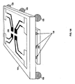
- FIG. 1A is diagram illustrating a phased array antenna in an integrated circuit package further explaining the invention.
- FIG. 1B is a diagram of an exemplary phased array antenna embedded in and/or on an IC package further explaining the invention.
- FIG. 2A is a diagram illustrating a cross sectional view of a multi-layer IC package with embedded phased array antenna, in accordance with an embodiment of the invention.
- FIG. 2B is a diagram illustrating a cross sectional view of a multi-layer IC package with embedded phased array antenna and phase shifters.
- FIG. 3 is a flow chart illustrating exemplary steps for transmitting signals utilizing a phased array antenna embedded in and/or on an IC package.
- FIG. 4 is a block diagram illustrating an exemplary wireless device.
- Embodiments of the invention are found in a method and system for a phased array antenna embedded in a multi-layer integrated circuit (IC) package for transmitting and/or receiving signals.
- the multi-layer package may comprise one or more metal layers, insulating material, ferromagnetic, and/or ferrimagnetic materials.
- the antenna may comprise one or more planar transmission lines.
- the phased array antenna may comprise a plurality of antenna elements and each antenna element may comprise an interconnection for communicatively coupling to an associated transmitter and/or receiver, a feeder line, a quarter wavelength transformer, and a radiating portion (e.g., a folded dipole).
- an IC enabled to transmit and/or receive signals is bonded to the multi-layer IC package, e.g. via one or more solder balls. Accordingly, the IC communicates a reference signal and one or more phase shifted versions of said reference signal to the antenna.
- One or more phase shifters (fabricated, for example, in planar transmission line) may be embedded in the multi-layer IC package and may be controlled via logic, circuitry, and/or code within an IC bonded to the multi-layer IC package.
- FIG. 1A is diagram illustrating a configurable antenna embedded in and/or on an integrated circuit package, in accordance with an embodiment of the invention.
- IC integrated circuit
- FIG. 1 there is shown an multi-layer Integrated circuit (IC) package 104, an associated IC ("chip”) 106, a phased array antenna 102, and solder balls 108.
- IC integrated circuit
- the IC 106 may comprise suitable logic, circuitry, and/or code for performing one or more functions associated with transmitting and/or receiving RF signals.
- the IC 106 may comprise all or a portion of the system 420 described with respect to FIG. 4 .
- the IC 106 utilizes a phased array antenna embedded in the package 104 for transmitting and/or receiving RF signals.
- the IC 106 comprises suitable logic, circuitry and/or code for driving the antenna 102 with a plurality of phase shifted signals.
- the IC 106 comprises a transmitter and/or a receiver.
- the IC 106 comprises phase shifting circuitry and is coupled to a separate transmitter and/or receiver (e.g., via one or more traces on a PCB).
- the IC 106 may be bump-bonded or flip-chip bonded to the multi-layer IC package 104 utilizing the solder balls 108. In this manner, wire bonds connecting the IC 106 to the multi-layer IC package 104 may be eliminated, reducing and/or eliminating uncontrollable stray inductances due to wire bonds. In addition, the thermal conductance out of the IC 106 may be greatly improved utilizing the solder balls 108 and the thermal epoxy 206 ( FIG. 2 ).
- the thermal epoxy 221 may be electrically insulating but thermally conductive to allow for thermal energy to be conducted out of the IC 106 to the much larger thermal mass of the multilayer package 104.
- the solder balls 108 may comprise spherical balls of metal to provide electrical, thermal and physical contact between the IC 106 and the multi-layer IC package 104.
- the IC may be pressed with enough force to squash the metal spheres somewhat, and may be performed at an elevated temperature to provide suitable electrical resistance and physical bond strength.
- the solder balls 108 may also be utilized to provide electrical, thermal and physical contact between the multi-layer IC package 104 and a printed circuit board comprising other parts of the wireless system 420, described with respect to FIG. 4 .
- the multi-layer IC package 104 may comprise one or more layers of metal and/or insulating material (various embodiments may also comprise ferromagnetic and/or ferromagnetic areas and/or layers).
- the package 104 may be fabricated in a manner similar to or the same as an IC. Accordingly, the layers may be utilized to realize circuit elements such as resistors, inductors, capacitors, transmission lines, switches, antennas, etc.
- a plurality of elements of the phased array antenna 102 may be fabricated in and/or on the package 104. Accordingly, each of the plurality of antenna elements may transmit and/or receive signals which are phase shifted with respect to other transmitted and/or received signals.
- the phased array antenna 102 may comprise a plurality of antenna elements which may each be a metallic and/or conductive structure capable of coupling RF energy to/from, for example, the transceiver 423 described with respect to FIG. 420.
- each element may be rectangular, circular, and/or another shape.
- One or more of the elements may be coupled (by way of one or more vias and/or one or more metal layers) to one or more of the solder balls 108. In this manner, signals may be conveyed to/from the package 104.
- four elements corresponding to four phases are utilized. Accordingly, four phase shifted representations of a reference signal are transmitted and/or received via the antenna 102. Details of the exemplary four element phased array antenna are described below with respect to FIG. 1B .
- logic, circuitry, and/or code in the IC 106 and/or in another device coupled to the package 104 may transmit and/or receive signals via the phased array antenna 102.
- the phasing of the signals coupled to the antenna elements may be controlled to achieve a desired radiation pattern. In this manner, sensitivity and/or power in a desired direction may be increased over sensitivity and/or power in another direction.
- FIG. 1B is a diagram of an exemplary phased array antenna embedded in and/or on an IC package for further explanation of the invention.
- the phased array antenna may comprise four antenna elements 150 1 ..., 150 4 (referred collectively herein as 150).
- Each element 150 may comprise a folded dipole radiating element 152 1 ..., 152 4 (referred collectively herein as 152), a quarter wavelength transformer 154 1 ..., 154 4 (referred collectively herein as 154), a feeder line 156 1 ..., 156 4 (referred collectively herein as 156), and an interconnection 158 1 ..., 1584 (referred collectively herein as 158).
- the folded dipole radiating elements 152 may each be a metallic and/or conductive material capable of receiving and/or transmitting RF energy via a wireless channel/medium.
- the dipole radiating elements 152 1 - 152 4 may be fabricated in, for example, planar transmission line (e.g., microstrip and/or stripline). The physical size of the dipoles may affect which frequency band(s) are best transmitted and/or received.
- Each dipole radiating element 152 may transmit a signal which may be phase shifted relative to the signal transmitted by the other dipole radiating elements 152.
- the quarter wavelength transformers 154 may each be a length of, for example, planar transmission line (e.g., microstrip and/or stripline).
- the length and/or width of quarter wavelength transformer may depend on the frequency of transmission and/or reception as well as the impedance of the dipole radiating elements 152 and the feeder lines 156.
- the quarter wavelength transformers 154 may impedance match the feeder lines to the folded dipole radiating elements 152.
- the feeder lines 156 may each be a length of, for example, planar or coplanar transmission line utilized to couple RF signals to from the folded dipole radiating elements 152.
- the interconnections 158 may each be a via and/or one or more metal layers in the package 104 which couple the feeder lines 156 to one or more solder balls 108 which couple the package 104 to the IC 106.
- the phased array antenna 102 may be designed to transmit and/or receive signals at or near 60GHz.
- an exemplary embodiment may be realized on an approximately 5mm by 5mm multi-layer integrated circuit package.
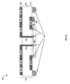
- FIG. 2A is a diagram illustrating a cross sectional view of a multi-layer IC package with embedded phased array antenna, in accordance with an embodiment of the invention.
- a system 200 comprising a IC 106 and a multi-layer IC package 104.
- the multi-layer IC package 104 may comprise an insulating material 203, and metal layers 202 and 210. Although only two metal layers are shown, various embodiments of the invention may comprise any number of metal layers.
- the phased array antenna 102 may be fabricated in the metal layer 202 and one or more other components such as resistors, capacitors, inductors, transmission lines, phase shifters, etc. may be fabricated in the metal layer 210.
- the IC 106 may be communicatively coupled to the package 104, and the package 104 to a PCB (not shown), via solder balls 108.
- One or more surface mount components 208 may be mounted to the package 104.
- Thermal epoxy (or similar material) 206 may be pressed between the IC 106 and the package 104.
- the IC 106 may be as described with respect to FIG. 1 .
- the solder balls 108 may be as described with respect to FIG. 1 .
- the surface mount device 208 may comprise a discrete circuit element such as a resistor, capacitor, inductor, or diode, for example.
- the surface mount device 208 may be soldered to the multi-layer IC package 104 to provide electrical contact.
- additional surface mount elements or no surface mount elements may be coupled to the package 104.
- the metal layer 202 may comprise a deposited metal layer utilized to delineate the phased array antenna 102 described with respect to FIG. 1A and 1B .
- the metal layer 202 may be deposited as, for example, planar transmission line (e.g. microstrip) in shapes and/or sizes which enable realizing, for example, folded dipole radiating elements 152, quarter wavelength transformers 154, and feeder lines 156.
- the interconnections 158 may be realized in the form of one of more vias which may be communicatively coupled the phased array antenna 102 to one or more of the solder balls 108.
- the metal layer 210 may comprise deposited metal layers utilized to delineate discrete components, waveguides, transmission lines, interconnections, etc.
- the component 204a may be an inductor fabricated in metal layer 210.
- the transmission line 204b may couple the discrete component 208 to a solder ball 108. In this manner, signals may be conveyed to and/or from the antenna elements 102 in the metal layer 202.
- the IC 106 and associated package 104 is utilized to transmit and/or receive RF signals.
- the IC 106 is communicatively coupled to the phased array antenna embedded on and/or within the multi-layer IC package 104.
- the directivity of the phased array antenna is controlled by altering the phases of signals sent and/or received to/from the phased array antenna.
- a signal to be transmitted may be modulated onto an RF carrier and four phase-shifted versions of the RF carrier may be generated.
- each signal may be coupled, via one or more solder balls 108, to the antenna 102.
- each signal may be coupled to a corresponding folded dipole radiating element 152 via an interconnection 158, feeder line 156, and quarter wavelength transformer 154.
- FIG. 2B is a diagram illustrating a cross sectional view of a multi-layer IC package with embedded configurable antenna and phase shifters.
- a multi-layer IC package 104 with integrated phased array antenna similar to FIG. 2B .
- FIG. 2B differs from FIG. 2A in that the package 104 in FIG. 2B comprises phase shifter 252.
- an RF signal coupled from interconnection 158, to the IC 106 may experience a first phase delay while an RF signal coupled from the interconnection 158 3 may experience a second phase delay.
- signals to additional interconnections 158 each may experience a different phase shift.
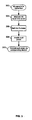
- FIG. 3 is a flow chart illustrating exemplary steps for transmitting signals utilizing a phased array antenna embedded in a multi-layer IC package.
- the exemplary steps may begin with step 302 when a baseband signal may be ready for transmission. Subsequent to step 302, the exemplary steps may advance to step 304.
- the baseband signal may be modulated onto a carrier signal.
- the baseband signal may be split into in-phase and quadrature phase signals and modulated onto a pair of phase quadrature carrier signals.
- various embodiments of the invention may utilize carriers at or near 60GHz.
- the modulated signals may then be combined to generate an RF signal.
- the exemplary steps may advance to step 306.
- step 306 the RF signal generated in step 304 may be split into a plurality of phases.
- the signal may be split into four phases.
- the phasing of the signals may be utilized to control the directivity of the phased array antenna.
- the exemplary steps may advance to step 308.
- step 308 the RF signals may be amplified.
- a power amplifier may amplify the signals such that sufficient signal strength may be radiated via the phased array antenna.
- the exemplary steps may advance to step 310.
- the amplified signals may be conveyed to the phased array antenna for transmission.
- a number of phases may be conveyed to a corresponding number of radiating elements.
- Steps similar to those described with respect to FIG. 3 may also be applied to receiving signals via a phased array antenna integrated into an IC package.
- FIG. 4 is a block diagram illustrating an exemplary wireless device for further explanation of the invention.
- a wireless device 420 may comprise an RF receiver 423, an RF transmitter 423, a digital baseband processor 429, a processor 425, and a memory 427.
- a receive antenna 421a may be communicatively coupled to the RF receiver 423.
- a transmit antenna 421b may be communicatively coupled to the RF transmitter 423.
- the wireless device 420 may be operated in a system, such as the cellular network and/or digital video broadcast network, for example.
- the antenna(s) 421a and 421b may be phased array antennas, similar to or the same as the antenna 102 described with respect to FIG. 1A .
- the directivity of the antennas may be controlled by controlling the phase(s) of signals coupled to the antenna.
- the RF receiver 423 may comprise suitable logic, circuitry, and/or code that may enable processing of received RF signals.
- the RF receiver 423 may enable receiving RF signals in a plurality of frequency bands.
- the RF receiver 423 may enable receiving signals in extremely high frequency (e.g., 60GHz) bands.
- the receiver 423 may be enabled to receive, filter, amplify, down-convert, and/or perform analog to digital conversion.
- the RF receiver 423 may down convert a received RF signal.
- the RF receiver 423 may perform direct down conversion of the received RF signal to a baseband or may convert the received RF signal to an intermediate frequency (IF).
- IF intermediate frequency
- the receiver 423 may perform quadrature down-conversion where in-phase components and quadrature phase components may be processed in parallel.
- the receiver 423 may be enabled to receive signals via the antenna 421 a, which may be a phased array antenna embedded in and/or on an integrated circuit package, as described with respect to FIGS. 1A , 1B , 2A , and 2B .
- the wireless device 420 may comprise a plurality of the receivers 423 and may thus support multiple frequency bands and or simultaneous reception of signals in the same frequency band.
- the digital baseband processor 429 may comprise suitable logic, circuitry, and/or code that may enable processing and/or handling of baseband signals.
- the digital baseband processor 429 may process or handle signals received from the RF receiver 423 and/or signals to be transferred to the RF transmitter 423 when the RF transmitter 423 is present, for transmission to the network.
- the digital baseband processor 429 may also provide control and/or feedback information to the RF receiver 423 and to the RF transmitter 423 based on information from the processed signals.
- the baseband processor 429 may provide one or more control signals for configuring phase shifting of received and/or transmitted RF signals.
- the phase shift applied to RF signals may enable controlling the directivity of the phased array antenna.
- the digital baseband processor 429 may communicate information and/or data from the processed signals to the processor 425 and/or to the memory 427. Moreover, the digital baseband processor 429 may receive information from the processor 425 and/or to the memory 427, which may be processed and transferred to the RF transmitter 423 for transmission to the network.
- the RF transmitter 423 may comprise suitable logic, circuitry, and/or code that may enable processing of RF signals for transmission.
- the transmitter 423 may be enabled to transmit signals via the antenna 421b, which may be a phased array antenna fabricated in an integrated circuit package as described with respect to FIGs. 1A , 1B , 2A , and 2B .
- the RF transmitter 423 may enable transmission of RF signals in a plurality of frequency bands.
- the RF transmitter 423 may enable transmitting signals in extremely high frequency (e.g., 60GHz) bands.
- Each frequency band supported by the RF transmitter 423 may have a corresponding front-end circuit for handling amplification and up conversion operations, for example.
- the RF transmitter 423 may be referred to as a multi-band transmitter when it supports more than one frequency band.
- the wireless device 420 may comprise more than one RF transmitter 423, wherein each of the RF transmitter 423 may be a single-band or a multi-band transmitter.
- the RF transmitter 423 may perform direct up conversion of the baseband signal to an RF signal. In some instances, the RF transmitter 423 may enable digital-to-analog conversion of the baseband signal components received from the digital baseband processor 429 before up conversion. In other instances, the RF transmitter 423 may receive baseband signal components in analog form.
- the processor 425 may comprise suitable logic, circuitry, and/or code that may enable control and/or data processing operations for the wireless device 420.
- the processor 425 may be utilized to control at least a portion of the RF receiver 423, the RF transmitter 423, the digital baseband processor 429, and/or the memory 427.
- the processor 425 may generate at least one signal for controlling operations within the wireless device 420.
- the baseband processor 429 may provide one or more control signals for controlling a phase of signals transmitted and/or received via the phased array antennas 421 a and 421 b.
- the processor 425 may also enable executing of applications that may be utilized by the wireless device 420.
- the processor 425 may execute applications that may enable displaying and/or interacting with content received via cellular transmission signals in the wireless device 420.
- the memory 427 may comprise suitable logic, circuitry, and/or code that may enable storage of data and/or other information utilized by the wireless device 420.
- the memory 427 may be utilized for storing processed data generated by the digital baseband processor 429 and/or the processor 425.
- the memory 427 may also be utilized to store information, such as configuration information, that may be utilized to control the operation of at least one block in the wireless device 420.
- the memory 427 may comprise information necessary to control phase of signals transmitted and/or received via the antenna(s) 421a and 421b.
- the memory may store control and/or configuration information for configuring one or more phase shifters.
- a phased array antenna (e.g., 102) embedded in a multi-layer integrated circuit (IC) package (e.g., 104) may be utilized for transmitting and/or receiving signals.
- the multi-layer package may comprise one or more metal layers (e.g., 202 and 210), insulating material (e.g., 203), ferromagnetic, and/or ferrimagnetic material.
- the antenna may comprise one or more planar transmission lines.
- the phased array antenna may comprise a plurality of antenna elements (e.g., 150) and each antenna element may comprise an interconnection (e.g., 158) for communicatively coupling to an associated transmitter and/or receiver, a feeder line (e.g., 156), a quarter wavelength transformer (e.g., 154), and a radiating portion (e.g. folded dipole 152).
- an IC e.g., 106 enabled to transmit and/or receive signals is bonded to the multi-layer IC package via one or more solder balls (e.g., 211). Accordingly, the IC communicates a reference signal and one or more phase shifted versions of said reference signal to the antenna.
- phase shifters e.g., 252
- fabricated, for example, in planar transmission line may be embedded in the multi-layer IC package and may be controlled via logic, circuitry, and/or code within an IC bonded to the multi-layer IC package.
- the present invention may be realized in hardware, or a combination of hardware and software.
- the present invention may be realized in a centralized fashion in at least one computer system, or in a distributed fashion where different elements are spread across several interconnected computer systems. Any kind of computer system or other apparatus adapted for carrying out the methods described herein is suited.
- a typical combination of hardware and software may be a general-purpose computer system with a computer program that, when being loaded and executed, controls the computer system such that it carries out the methods described herein.
Landscapes
- Engineering & Computer Science (AREA)
- Manufacturing & Machinery (AREA)
- Computer Networks & Wireless Communication (AREA)
- Signal Processing (AREA)
- Variable-Direction Aerials And Aerial Arrays (AREA)
- Details Of Aerials (AREA)
Claims (8)
- Verfahren zur Signalverarbeitung, wobei das Verfahren umfasst:- Senden und/oder Empfangen von Signalen über eine phasengesteuerte Antenne (102, 421 a, 421 b), die in eine mehrschichtige integrierte Schaltungsbaugruppe (104) eingebettet ist, welche mit einer integrierten Schaltung (106) verbunden ist, und- wobei die integrierte Schaltung (106) das Senden und/oder Empfangen durch Ändern der Phasenlage der Signale ermöglicht,
dadurch gekennzeichnet, dass die integrierte Schaltung (106) ein Referenzsignal und eine oder mehrere phasenverschobene Versionen des Referenzsignals an die phasengesteuerte Antenne (102, 421 a, 421 b) übermittelt. - Verfahren nach Anspruch 1,
wobei die integrierte Schaltung (106), die dazu in der Lage ist, das Senden und/oder Empfangen durchzuführen, über eine oder mehrere Lotkugeln (108) mit der mehrschichtigen integrierten Schaltungsbaugruppe (104) verbunden ist. - Verfahren nach Anspruch 1,
wobei der Abstrahlungsabschnitt (152) eine gefaltete Dipolstruktur ist. - Verfahren nach Anspruch 1,
wobei die mehrschichtige integrierte Schaltungsbaugruppe (104) eine oder mehrere Schichten (202, 210) aus ferromagnetischem und/oder ferrimagnetischem Material umfasst. - System zur Signalverarbeitung, wobei das System umfasst:- eine phasengesteuerte Antenne (102, 421 a, 421 b), die in eine mehrschichtige integrierte Schaltungsbaugruppe (104) eingebettet ist, welche mit einer integrierten Schaltung (106) verbunden ist, wobei die phasengesteuerte Antenne (102, 421a, 421 b) das Senden und/oder Empfangen eines Signals ermöglicht, und- wobei die integrierte Schaltung (106) das Senden und/oder Empfangen durch Ändern der Phasenlage der Signale ermöglicht,
dadurch gekennzeichnet, dass die integrierte Schaltung (106) ein Referenzsignal und eine oder mehrere phasenverschobene Versionen des Referenzsignals an die phasengesteuerte Antenne (102, 421 a, 421 b) übermittelt. - System nach Anspruch 5,
wobei die integrierte Schaltung (106) über eine oder mehrere Lotkugeln (108) mit der mehrschichtigen integrierten Schaltungsbaugruppe (104) verbunden ist. - System nach Anspruch 5,
wobei der Abstrahlungsabschnitt (152) eine gefaltete Dipolstruktur ist. - System nach Anspruch 5,
wobei die mehrschichtige integrierte Schaltungsbaugruppe (104) eine oder mehrere Schichten (202, 210) aus ferromagnetischem und/oder ferrimagnetischem Material umfasst.
Applications Claiming Priority (1)
| Application Number | Priority Date | Filing Date | Title |
|---|---|---|---|
| US11/954,822 US7880677B2 (en) | 2007-12-12 | 2007-12-12 | Method and system for a phased array antenna embedded in an integrated circuit package |
Publications (2)
| Publication Number | Publication Date |
|---|---|
| EP2071663A1 EP2071663A1 (de) | 2009-06-17 |
| EP2071663B1 true EP2071663B1 (de) | 2011-05-25 |
Family
ID=40383857
Family Applications (1)
| Application Number | Title | Priority Date | Filing Date |
|---|---|---|---|
| EP08020760A Active EP2071663B1 (de) | 2007-12-12 | 2008-11-28 | Eine in einem integrierten Schaltungspaket eingebettete Phasenarray-Antenne |
Country Status (5)
| Country | Link |
|---|---|
| US (3) | US7880677B2 (de) |
| EP (1) | EP2071663B1 (de) |
| KR (1) | KR101150249B1 (de) |
| CN (1) | CN101459168B (de) |
| TW (1) | TWI414108B (de) |
Families Citing this family (150)
| Publication number | Priority date | Publication date | Assignee | Title |
|---|---|---|---|---|
| US8873585B2 (en) | 2006-12-19 | 2014-10-28 | Corning Optical Communications Wireless Ltd | Distributed antenna system for MIMO technologies |
| US7675465B2 (en) | 2007-05-22 | 2010-03-09 | Sibeam, Inc. | Surface mountable integrated circuit packaging scheme |
| US8106829B2 (en) | 2007-12-12 | 2012-01-31 | Broadcom Corporation | Method and system for an integrated antenna and antenna management |
| US8270912B2 (en) * | 2007-12-12 | 2012-09-18 | Broadcom Corporation | Method and system for a transformer in an integrated circuit package |
| US8160498B2 (en) * | 2007-12-12 | 2012-04-17 | Broadcom Corporation | Method and system for portable data storage with integrated 60 GHz radio |
| WO2009081376A2 (en) | 2007-12-20 | 2009-07-02 | Mobileaccess Networks Ltd. | Extending outdoor location based services and applications into enclosed areas |
| US8064936B2 (en) * | 2008-02-28 | 2011-11-22 | Broadcom Corporation | Method and system for a multistandard proxy |
| US8086190B2 (en) * | 2008-03-27 | 2011-12-27 | Broadcom Corporation | Method and system for reconfigurable devices for multi-frequency coexistence |
| US8072287B2 (en) * | 2008-03-27 | 2011-12-06 | Broadcom Corporation | Method and system for configurable differential or single-ended signaling in an integrated circuit |
| US8198714B2 (en) | 2008-03-28 | 2012-06-12 | Broadcom Corporation | Method and system for configuring a transformer embedded in a multi-layer integrated circuit (IC) package |
| EP2344915A4 (de) | 2008-10-09 | 2015-01-21 | Corning Cable Sys Llc | Faseroptischer anschluss mit adaptertafel, die sowohl eingangs- als auch ausgangsfasern von einem optischen teiler unterstützt |
| EP2178119B1 (de) * | 2008-10-20 | 2018-06-20 | QUALCOMM Incorporated | Gehäuse für oberflächenmontierbare integrierte Schaltkreise |
| WO2010058337A1 (en) * | 2008-11-19 | 2010-05-27 | Nxp B.V. | Millimetre-wave radio antenna module |
| US8554136B2 (en) | 2008-12-23 | 2013-10-08 | Waveconnex, Inc. | Tightly-coupled near-field communication-link connector-replacement chips |
| AU2010210766A1 (en) | 2009-02-03 | 2011-09-15 | Corning Cable Systems Llc | Optical fiber-based distributed antenna systems, components, and related methods for monitoring and configuring thereof |
| US9673904B2 (en) | 2009-02-03 | 2017-06-06 | Corning Optical Communications LLC | Optical fiber-based distributed antenna systems, components, and related methods for calibration thereof |
| EP2394379B1 (de) | 2009-02-03 | 2016-12-28 | Corning Optical Communications LLC | Verteilte antennensysteme auf glasfaserbasis, bestandteile und entsprechende verfahren zu ihrer kalibrierung |
| US8588686B2 (en) * | 2009-06-09 | 2013-11-19 | Broadcom Corporation | Method and system for remote power distribution and networking for passive devices |
| US8447250B2 (en) | 2009-06-09 | 2013-05-21 | Broadcom Corporation | Method and system for an integrated voltage controlled oscillator-based transmitter and on-chip power distribution network |
| US9590733B2 (en) | 2009-07-24 | 2017-03-07 | Corning Optical Communications LLC | Location tracking using fiber optic array cables and related systems and methods |
| WO2011025241A2 (ko) * | 2009-08-26 | 2011-03-03 | 연세대학교 산학협력단 | 본딩 와이어 안테나 통신 모듈 |
| US9059503B2 (en) | 2009-10-29 | 2015-06-16 | Technische Universitat Dresden | Antenna arrangement for transmitting signals |
| US8280259B2 (en) | 2009-11-13 | 2012-10-02 | Corning Cable Systems Llc | Radio-over-fiber (RoF) system for protocol-independent wired and/or wireless communication |
| US8502735B1 (en) * | 2009-11-18 | 2013-08-06 | Ball Aerospace & Technologies Corp. | Antenna system with integrated circuit package integrated radiators |
| US9401745B1 (en) * | 2009-12-11 | 2016-07-26 | Micron Technology, Inc. | Wireless communication link using near field coupling |
| US8275265B2 (en) | 2010-02-15 | 2012-09-25 | Corning Cable Systems Llc | Dynamic cell bonding (DCB) for radio-over-fiber (RoF)-based networks and communication systems and related methods |
| WO2011123336A1 (en) | 2010-03-31 | 2011-10-06 | Corning Cable Systems Llc | Localization services in optical fiber-based distributed communications components and systems, and related methods |
| US8570914B2 (en) | 2010-08-09 | 2013-10-29 | Corning Cable Systems Llc | Apparatuses, systems, and methods for determining location of a mobile device(s) in a distributed antenna system(s) |
| US9252874B2 (en) | 2010-10-13 | 2016-02-02 | Ccs Technology, Inc | Power management for remote antenna units in distributed antenna systems |
| AU2011317244A1 (en) | 2010-10-19 | 2013-05-23 | Corning Cable Systems Llc | Transition box for multiple dwelling unit fiber optic distribution network |
| EP2689492B1 (de) * | 2011-03-24 | 2020-01-08 | Keyssa, Inc. | Integrierte schaltung mit elektromagnetischer kommunikation |
| CN103548290B (zh) | 2011-04-29 | 2016-08-31 | 康宁光缆系统有限责任公司 | 判定分布式天线系统中的通信传播延迟及相关组件、系统与方法 |
| WO2012148940A1 (en) | 2011-04-29 | 2012-11-01 | Corning Cable Systems Llc | Systems, methods, and devices for increasing radio frequency (rf) power in distributed antenna systems |
| WO2012170865A2 (en) | 2011-06-09 | 2012-12-13 | Lgc Wireless, Llc | Antenna module having integrated radio frequency circuitry |
| KR20130062717A (ko) * | 2011-12-05 | 2013-06-13 | 삼성전기주식회사 | 밀리미터 대역용 알에프아이씨 안테나 패키지 및 이를 포함하는 무선모듈 |
| US9219546B2 (en) | 2011-12-12 | 2015-12-22 | Corning Optical Communications LLC | Extremely high frequency (EHF) distributed antenna systems, and related components and methods |
| US10110307B2 (en) | 2012-03-02 | 2018-10-23 | Corning Optical Communications LLC | Optical network units (ONUs) for high bandwidth connectivity, and related components and methods |
| WO2013148986A1 (en) | 2012-03-30 | 2013-10-03 | Corning Cable Systems Llc | Reducing location-dependent interference in distributed antenna systems operating in multiple-input, multiple-output (mimo) configuration, and related components, systems, and methods |
| US9781553B2 (en) | 2012-04-24 | 2017-10-03 | Corning Optical Communications LLC | Location based services in a distributed communication system, and related components and methods |
| EP2842245A1 (de) | 2012-04-25 | 2015-03-04 | Corning Optical Communications LLC | Verteilte antennensystemarchitekturen |
| TWI528468B (zh) | 2012-05-30 | 2016-04-01 | 國立中山大學 | 多輸入輸出天線、其天線單元及具有天線之系統封裝 |
| WO2014024192A1 (en) | 2012-08-07 | 2014-02-13 | Corning Mobile Access Ltd. | Distribution of time-division multiplexed (tdm) management services in a distributed antenna system, and related components, systems, and methods |
| US9515365B2 (en) | 2012-08-10 | 2016-12-06 | Keyssa, Inc. | Dielectric coupling systems for EHF communications |
| EP2896135B1 (de) | 2012-09-14 | 2019-08-14 | Keyssa, Inc. | Drahtlose verbindungen mit virtueller hysterese |
| US9455784B2 (en) | 2012-10-31 | 2016-09-27 | Corning Optical Communications Wireless Ltd | Deployable wireless infrastructures and methods of deploying wireless infrastructures |
| CN105308876B (zh) | 2012-11-29 | 2018-06-22 | 康宁光电通信有限责任公司 | 分布式天线系统中的远程单元天线结合 |
| US9647758B2 (en) | 2012-11-30 | 2017-05-09 | Corning Optical Communications Wireless Ltd | Cabling connectivity monitoring and verification |
| WO2014100058A1 (en) | 2012-12-17 | 2014-06-26 | Waveconnex, Inc. | Modular electronics |
| US9158864B2 (en) | 2012-12-21 | 2015-10-13 | Corning Optical Communications Wireless Ltd | Systems, methods, and devices for documenting a location of installed equipment |
| US10403511B2 (en) * | 2013-01-14 | 2019-09-03 | Intel Corporation | Backside redistribution layer patch antenna |
| KR101886739B1 (ko) | 2013-03-15 | 2018-08-09 | 키사, 아이엔씨. | 극고주파 통신 칩 |
| KR20150132459A (ko) | 2013-03-15 | 2015-11-25 | 키사, 아이엔씨. | Ehf 보안 통신 장치 |
| EP3008828B1 (de) | 2013-06-12 | 2017-08-09 | Corning Optical Communications Wireless Ltd. | Zeitduplexierung (tdd) in verteilten kommunikationssystemen, einschliesslich verteilten antennensystemen (dass) |
| WO2014199384A1 (en) | 2013-06-12 | 2014-12-18 | Corning Optical Communications Wireless, Ltd. | Voltage controlled optical directional coupler |
| US9247543B2 (en) | 2013-07-23 | 2016-01-26 | Corning Optical Communications Wireless Ltd | Monitoring non-supported wireless spectrum within coverage areas of distributed antenna systems (DASs) |
| US9661781B2 (en) | 2013-07-31 | 2017-05-23 | Corning Optical Communications Wireless Ltd | Remote units for distributed communication systems and related installation methods and apparatuses |
| US9385810B2 (en) | 2013-09-30 | 2016-07-05 | Corning Optical Communications Wireless Ltd | Connection mapping in distributed communication systems |
| US9178635B2 (en) | 2014-01-03 | 2015-11-03 | Corning Optical Communications Wireless Ltd | Separation of communication signal sub-bands in distributed antenna systems (DASs) to reduce interference |
| US9775123B2 (en) | 2014-03-28 | 2017-09-26 | Corning Optical Communications Wireless Ltd. | Individualized gain control of uplink paths in remote units in a distributed antenna system (DAS) based on individual remote unit contribution to combined uplink power |
| US9357551B2 (en) | 2014-05-30 | 2016-05-31 | Corning Optical Communications Wireless Ltd | Systems and methods for simultaneous sampling of serial digital data streams from multiple analog-to-digital converters (ADCS), including in distributed antenna systems |
| US9620841B2 (en) | 2014-06-13 | 2017-04-11 | Nxp Usa, Inc. | Radio frequency coupling structure |
| US9917372B2 (en) | 2014-06-13 | 2018-03-13 | Nxp Usa, Inc. | Integrated circuit package with radio frequency coupling arrangement |
| US10103447B2 (en) | 2014-06-13 | 2018-10-16 | Nxp Usa, Inc. | Integrated circuit package with radio frequency coupling structure |
| US9865600B2 (en) | 2014-06-18 | 2018-01-09 | X-Celeprint Limited | Printed capacitors |
| TWI652796B (zh) * | 2014-06-18 | 2019-03-01 | X-Celeprint Limited | 多層印刷電容器 |
| US9525472B2 (en) | 2014-07-30 | 2016-12-20 | Corning Incorporated | Reducing location-dependent destructive interference in distributed antenna systems (DASS) operating in multiple-input, multiple-output (MIMO) configuration, and related components, systems, and methods |
| US10225925B2 (en) | 2014-08-29 | 2019-03-05 | Nxp Usa, Inc. | Radio frequency coupling and transition structure |
| US9887449B2 (en) | 2014-08-29 | 2018-02-06 | Nxp Usa, Inc. | Radio frequency coupling structure and a method of manufacturing thereof |
| US9730228B2 (en) | 2014-08-29 | 2017-08-08 | Corning Optical Communications Wireless Ltd | Individualized gain control of remote uplink band paths in a remote unit in a distributed antenna system (DAS), based on combined uplink power level in the remote unit |
| US9444135B2 (en) * | 2014-09-19 | 2016-09-13 | Freescale Semiconductor, Inc. | Integrated circuit package |
| US9602210B2 (en) | 2014-09-24 | 2017-03-21 | Corning Optical Communications Wireless Ltd | Flexible head-end chassis supporting automatic identification and interconnection of radio interface modules and optical interface modules in an optical fiber-based distributed antenna system (DAS) |
| US9420542B2 (en) | 2014-09-25 | 2016-08-16 | Corning Optical Communications Wireless Ltd | System-wide uplink band gain control in a distributed antenna system (DAS), based on per band gain control of remote uplink paths in remote units |
| US9729267B2 (en) | 2014-12-11 | 2017-08-08 | Corning Optical Communications Wireless Ltd | Multiplexing two separate optical links with the same wavelength using asymmetric combining and splitting |
| US10725150B2 (en) | 2014-12-23 | 2020-07-28 | Infineon Technologies Ag | System and method for radar |
| US10317512B2 (en) | 2014-12-23 | 2019-06-11 | Infineon Technologies Ag | RF system with an RFIC and antenna system |
| US20160249365A1 (en) | 2015-02-19 | 2016-08-25 | Corning Optical Communications Wireless Ltd. | Offsetting unwanted downlink interference signals in an uplink path in a distributed antenna system (das) |
| US9681313B2 (en) | 2015-04-15 | 2017-06-13 | Corning Optical Communications Wireless Ltd | Optimizing remote antenna unit performance using an alternative data channel |
| US9667290B2 (en) | 2015-04-17 | 2017-05-30 | Apple Inc. | Electronic device with millimeter wave antennas |
| US9948349B2 (en) | 2015-07-17 | 2018-04-17 | Corning Optical Communications Wireless Ltd | IOT automation and data collection system |
| US10560214B2 (en) | 2015-09-28 | 2020-02-11 | Corning Optical Communications LLC | Downlink and uplink communication path switching in a time-division duplex (TDD) distributed antenna system (DAS) |
| US10790576B2 (en) | 2015-12-14 | 2020-09-29 | Commscope Technologies Llc | Multi-band base station antennas having multi-layer feed boards |
| US10452148B2 (en) | 2016-01-19 | 2019-10-22 | Infineon Technologies Ag | Wearable consumer device |
| US9648580B1 (en) | 2016-03-23 | 2017-05-09 | Corning Optical Communications Wireless Ltd | Identifying remote units in a wireless distribution system (WDS) based on assigned unique temporal delay patterns |
| US10236924B2 (en) | 2016-03-31 | 2019-03-19 | Corning Optical Communications Wireless Ltd | Reducing out-of-channel noise in a wireless distribution system (WDS) |
| US10622700B2 (en) | 2016-05-18 | 2020-04-14 | X-Celeprint Limited | Antenna with micro-transfer-printed circuit element |
| US10181653B2 (en) | 2016-07-21 | 2019-01-15 | Infineon Technologies Ag | Radio frequency system for wearable device |
| US10218407B2 (en) | 2016-08-08 | 2019-02-26 | Infineon Technologies Ag | Radio frequency system and method for wearable device |
| WO2018081146A1 (en) * | 2016-10-24 | 2018-05-03 | Anokiwave, Inc. | Beamforming integrated circuit with rf grounded material ring and integral thermal mass |
| US10466772B2 (en) | 2017-01-09 | 2019-11-05 | Infineon Technologies Ag | System and method of gesture detection for a remote device |
| US10505255B2 (en) | 2017-01-30 | 2019-12-10 | Infineon Technologies Ag | Radio frequency device packages and methods of formation thereof |
| US10056922B1 (en) * | 2017-06-14 | 2018-08-21 | Infineon Technologies Ag | Radio frequency device modules and methods of formation thereof |
| US10602548B2 (en) | 2017-06-22 | 2020-03-24 | Infineon Technologies Ag | System and method for gesture sensing |
| US10944180B2 (en) * | 2017-07-10 | 2021-03-09 | Viasat, Inc. | Phased array antenna |
| US11394103B2 (en) * | 2017-07-18 | 2022-07-19 | Samsung Electro-Mechanics Co., Ltd. | Antenna module and manufacturing method thereof |
| CN107332573B (zh) * | 2017-07-25 | 2021-04-13 | Oppo广东移动通信有限公司 | 一种射频电路、天线装置及电子设备 |
| TWI685144B (zh) * | 2017-11-30 | 2020-02-11 | 太盟光電科技股份有限公司 | 多訊號饋入表面黏著式的訊號收發模組 |
| CN108109984A (zh) * | 2017-12-07 | 2018-06-01 | 中芯长电半导体(江阴)有限公司 | 半导体封装结构及其制备方法 |
| US10746625B2 (en) | 2017-12-22 | 2020-08-18 | Infineon Technologies Ag | System and method of monitoring a structural object using a millimeter-wave radar sensor |
| US10312569B1 (en) | 2018-01-05 | 2019-06-04 | Cirocomm Technology Corp. | Surface-mounted signal transceiver module with multi-signal feed-in |
| US11346936B2 (en) | 2018-01-16 | 2022-05-31 | Infineon Technologies Ag | System and method for vital signal sensing using a millimeter-wave radar sensor |
| US11278241B2 (en) | 2018-01-16 | 2022-03-22 | Infineon Technologies Ag | System and method for vital signal sensing using a millimeter-wave radar sensor |
| US10795012B2 (en) | 2018-01-22 | 2020-10-06 | Infineon Technologies Ag | System and method for human behavior modelling and power control using a millimeter-wave radar sensor |
| US10576328B2 (en) | 2018-02-06 | 2020-03-03 | Infineon Technologies Ag | System and method for contactless sensing on a treadmill |
| US10705198B2 (en) | 2018-03-27 | 2020-07-07 | Infineon Technologies Ag | System and method of monitoring an air flow using a millimeter-wave radar sensor |
| US10775482B2 (en) | 2018-04-11 | 2020-09-15 | Infineon Technologies Ag | Human detection and identification in a setting using millimeter-wave radar |
| US10761187B2 (en) | 2018-04-11 | 2020-09-01 | Infineon Technologies Ag | Liquid detection using millimeter-wave radar sensor |
| US11189905B2 (en) | 2018-04-13 | 2021-11-30 | International Business Machines Corporation | Integrated antenna array packaging structures and methods |
| US10794841B2 (en) | 2018-05-07 | 2020-10-06 | Infineon Technologies Ag | Composite material structure monitoring system |
| US10553551B2 (en) * | 2018-05-08 | 2020-02-04 | Speedlink Technology Inc. | Impedance compensation of flip chip connection for RF communications |
| US10399393B1 (en) | 2018-05-29 | 2019-09-03 | Infineon Technologies Ag | Radar sensor system for tire monitoring |
| US10903567B2 (en) | 2018-06-04 | 2021-01-26 | Infineon Technologies Ag | Calibrating a phased array system |
| US11416077B2 (en) | 2018-07-19 | 2022-08-16 | Infineon Technologies Ag | Gesture detection system and method using a radar sensor |
| CN110808478A (zh) * | 2018-08-06 | 2020-02-18 | 康普技术有限责任公司 | 多层移相器驱动装置以及相关的电调系统和电调天线 |
| US10928501B2 (en) | 2018-08-28 | 2021-02-23 | Infineon Technologies Ag | Target detection in rainfall and snowfall conditions using mmWave radar |
| US11183772B2 (en) | 2018-09-13 | 2021-11-23 | Infineon Technologies Ag | Embedded downlight and radar system |
| US11125869B2 (en) | 2018-10-16 | 2021-09-21 | Infineon Technologies Ag | Estimating angle of human target using mmWave radar |
| US11360185B2 (en) | 2018-10-24 | 2022-06-14 | Infineon Technologies Ag | Phase coded FMCW radar |
| US11397239B2 (en) | 2018-10-24 | 2022-07-26 | Infineon Technologies Ag | Radar sensor FSM low power mode |
| EP3654053A1 (de) | 2018-11-14 | 2020-05-20 | Infineon Technologies AG | Verpackung mit akustischen sensorvorrichtungen und millimeterwellenabtastelementen |
| US10862192B2 (en) * | 2018-12-18 | 2020-12-08 | Texas Instruments Incorporated | Non-contact test solution for antenna-on-package (AOP) devices using near-field coupled RF loopback paths |
| US11087115B2 (en) | 2019-01-22 | 2021-08-10 | Infineon Technologies Ag | User authentication using mm-Wave sensor for automotive radar systems |
| US11355838B2 (en) | 2019-03-18 | 2022-06-07 | Infineon Technologies Ag | Integration of EBG structures (single layer/multi-layer) for isolation enhancement in multilayer embedded packaging technology at mmWave |
| US11126885B2 (en) | 2019-03-21 | 2021-09-21 | Infineon Technologies Ag | Character recognition in air-writing based on network of radars |
| US11454696B2 (en) | 2019-04-05 | 2022-09-27 | Infineon Technologies Ag | FMCW radar integration with communication system |
| US11327167B2 (en) | 2019-09-13 | 2022-05-10 | Infineon Technologies Ag | Human target tracking system and method |
| US11774592B2 (en) | 2019-09-18 | 2023-10-03 | Infineon Technologies Ag | Multimode communication and radar system resource allocation |
| WO2021079361A1 (en) * | 2019-10-21 | 2021-04-29 | Rfisee Ltd | Antenna-on-package array |
| US11435443B2 (en) | 2019-10-22 | 2022-09-06 | Infineon Technologies Ag | Integration of tracking with classifier in mmwave radar |
| US11808883B2 (en) | 2020-01-31 | 2023-11-07 | Infineon Technologies Ag | Synchronization of multiple mmWave devices |
| US11614516B2 (en) | 2020-02-19 | 2023-03-28 | Infineon Technologies Ag | Radar vital signal tracking using a Kalman filter |
| US11585891B2 (en) | 2020-04-20 | 2023-02-21 | Infineon Technologies Ag | Radar-based vital sign estimation |
| US11567185B2 (en) | 2020-05-05 | 2023-01-31 | Infineon Technologies Ag | Radar-based target tracking using motion detection |
| KR102821886B1 (ko) | 2020-06-17 | 2025-06-16 | 삼성전자주식회사 | 안테나 패턴을 포함하는 반도체 패키지 |
| US11774553B2 (en) | 2020-06-18 | 2023-10-03 | Infineon Technologies Ag | Parametric CNN for radar processing |
| US11704917B2 (en) | 2020-07-09 | 2023-07-18 | Infineon Technologies Ag | Multi-sensor analysis of food |
| KR102738998B1 (ko) | 2020-07-13 | 2024-12-06 | 삼성전자주식회사 | 안테나 및 이를 포함하는 전자 장치 |
| US11614511B2 (en) | 2020-09-17 | 2023-03-28 | Infineon Technologies Ag | Radar interference mitigation |
| US11719787B2 (en) | 2020-10-30 | 2023-08-08 | Infineon Technologies Ag | Radar-based target set generation |
| EP4241383A4 (de) | 2020-11-03 | 2024-07-17 | Intel Corporation | Verteiltes funkkopfsystem |
| US11719805B2 (en) | 2020-11-18 | 2023-08-08 | Infineon Technologies Ag | Radar based tracker using empirical mode decomposition (EMD) and invariant feature transform (IFT) |
| US12189021B2 (en) | 2021-02-18 | 2025-01-07 | Infineon Technologies Ag | Radar-based target tracker |
| US11662430B2 (en) | 2021-03-17 | 2023-05-30 | Infineon Technologies Ag | MmWave radar testing |
| KR20220141013A (ko) * | 2021-04-12 | 2022-10-19 | 삼성전자주식회사 | 위상 시프터를 포함하는 안테나 구조 및 이를 포함하는 전자 장치 |
| US11950895B2 (en) | 2021-05-28 | 2024-04-09 | Infineon Technologies Ag | Radar sensor system for blood pressure sensing, and associated method |
| US12307761B2 (en) | 2021-08-06 | 2025-05-20 | Infineon Technologies Ag | Scene-adaptive radar |
| US12405351B2 (en) | 2022-03-25 | 2025-09-02 | Infineon Technologies Ag | Adaptive Tx-Rx crosstalk cancellation for radar systems |
| US12399254B2 (en) | 2022-06-07 | 2025-08-26 | Infineon Technologies Ag | Radar-based single target vital sensing |
| US12399271B2 (en) | 2022-07-20 | 2025-08-26 | Infineon Technologies Ag | Radar-based target tracker |
| US12254670B2 (en) | 2022-07-29 | 2025-03-18 | Infineon Technologies Ag | Radar-based activity classification |
| US12504526B2 (en) | 2022-09-21 | 2025-12-23 | Infineon Technologies Ag | Radar-based segmented presence detection |
Citations (1)
| Publication number | Priority date | Publication date | Assignee | Title |
|---|---|---|---|---|
| WO1996021255A1 (en) * | 1995-01-06 | 1996-07-11 | Georgia Tech Research Corporation | Curtain antenna |
Family Cites Families (63)
| Publication number | Priority date | Publication date | Assignee | Title |
|---|---|---|---|---|
| JPH0319358A (ja) | 1989-06-16 | 1991-01-28 | Matsushita Electron Corp | 半導体集積回路 |
| US5015972A (en) * | 1989-08-17 | 1991-05-14 | Motorola, Inc. | Broadband RF transformer |
| US5003622A (en) * | 1989-09-26 | 1991-03-26 | Astec International Limited | Printed circuit transformer |
| JPH06326510A (ja) * | 1992-11-18 | 1994-11-25 | Toshiba Corp | ビーム走査アンテナ及びアレーアンテナ |
| US5861853A (en) * | 1997-05-07 | 1999-01-19 | Motorola, Inc. | Current balanced balun network with selectable port impedances |
| US5914873A (en) * | 1997-06-30 | 1999-06-22 | Advanced Micro Devices | Distributed voltage converter apparatus and method for high power microprocessor with array connections |
| US5798567A (en) * | 1997-08-21 | 1998-08-25 | Hewlett-Packard Company | Ball grid array integrated circuit package which employs a flip chip integrated circuit and decoupling capacitors |
| US6060433A (en) | 1998-01-26 | 2000-05-09 | Nz Applied Technologies Corporation | Method of making a microwave device having a polycrystalline ferrite substrate |
| JP2000196329A (ja) | 1998-12-24 | 2000-07-14 | Nec Corp | フェーズドアレイアンテナおよびその製造方法 |
| US6573808B1 (en) * | 1999-03-12 | 2003-06-03 | Harris Broadband Wireless Access, Inc. | Millimeter wave front end |
| WO2001077698A2 (en) * | 2000-04-04 | 2001-10-18 | Contact Technology Systems, Inc. | Power line testing device with signal generator and signal detector |
| US6856225B1 (en) * | 2000-05-17 | 2005-02-15 | Xerox Corporation | Photolithographically-patterned out-of-plane coil structures and method of making |
| US7247932B1 (en) * | 2000-05-19 | 2007-07-24 | Megica Corporation | Chip package with capacitor |
| US7710199B2 (en) * | 2000-09-12 | 2010-05-04 | Black Sand Technologies, Inc. | Method and apparatus for stabilizing RF power amplifiers |
| WO2002096166A1 (en) * | 2001-05-18 | 2002-11-28 | Corporation For National Research Initiatives | Radio frequency microelectromechanical systems (mems) devices on low-temperature co-fired ceramic (ltcc) substrates |
| JP4135861B2 (ja) | 2001-10-03 | 2008-08-20 | 日本電波工業株式会社 | 多素子平面アンテナ |
| CN100367564C (zh) * | 2001-12-04 | 2008-02-06 | 松下电器产业株式会社 | 天线以及具有该天线的装置 |
| US6801114B2 (en) * | 2002-01-23 | 2004-10-05 | Broadcom Corp. | Integrated radio having on-chip transformer balun |
| US6646581B1 (en) * | 2002-02-28 | 2003-11-11 | Silicon Laboratories, Inc. | Digital-to-analog converter circuit incorporating hybrid sigma-delta modulator circuit |
| US6809581B2 (en) * | 2002-04-23 | 2004-10-26 | Broadcom Corp. | Integrated circuit low noise amplifier and applications thereof |
| US7260424B2 (en) | 2002-05-24 | 2007-08-21 | Schmidt Dominik J | Dynamically configured antenna for multiple frequencies and bandwidths |
| JP2003347844A (ja) * | 2002-05-29 | 2003-12-05 | Fujitsu Ltd | 電圧制御発振器、pll回路及び半導体装置 |
| US6731248B2 (en) * | 2002-06-27 | 2004-05-04 | Harris Corporation | High efficiency printed circuit array of log-periodic dipole arrays |
| US20040010554A1 (en) * | 2002-07-15 | 2004-01-15 | Hall John M. | Determining a destination e-mail address for sending scanned documents |
| US7138884B2 (en) | 2002-08-19 | 2006-11-21 | Dsp Group Inc. | Circuit package integrating passive radio frequency structure |
| US7141883B2 (en) | 2002-10-15 | 2006-11-28 | Silicon Laboratories Inc. | Integrated circuit package configuration incorporating shielded circuit element structure |
| KR100498484B1 (ko) * | 2003-01-30 | 2005-07-01 | 삼성전자주식회사 | 넓은 주파수 대역에서 일정한 이득을 가지는 전압 제어발진기 및 그 방법 |
| US6975267B2 (en) | 2003-02-05 | 2005-12-13 | Northrop Grumman Corporation | Low profile active electronically scanned antenna (AESA) for Ka-band radar systems |
| US7151506B2 (en) * | 2003-04-11 | 2006-12-19 | Qortek, Inc. | Electromagnetic energy coupling mechanism with matrix architecture control |
| US7391372B2 (en) * | 2003-06-26 | 2008-06-24 | Hrl Laboratories, Llc | Integrated phased array antenna |
| US6856297B1 (en) | 2003-08-04 | 2005-02-15 | Harris Corporation | Phased array antenna with discrete capacitive coupling and associated methods |
| DE10336171B3 (de) | 2003-08-07 | 2005-02-10 | Technische Universität Braunschweig Carolo-Wilhelmina | Multichip-Schaltungsmodul und Verfahren zur Herstellung hierzu |
| US6933789B2 (en) * | 2003-11-13 | 2005-08-23 | Skyworks Solutions, Inc. | On-chip VCO calibration |
| JP4335661B2 (ja) | 2003-12-24 | 2009-09-30 | Necエレクトロニクス株式会社 | 高周波モジュールの製造方法 |
| US7196607B2 (en) * | 2004-03-26 | 2007-03-27 | Harris Corporation | Embedded toroidal transformers in ceramic substrates |
| US7119745B2 (en) | 2004-06-30 | 2006-10-10 | International Business Machines Corporation | Apparatus and method for constructing and packaging printed antenna devices |
| US7081800B2 (en) * | 2004-06-30 | 2006-07-25 | Intel Corporation | Package integrated one-quarter wavelength and three-quarter wavelength balun |
| US7053847B2 (en) | 2004-08-11 | 2006-05-30 | Northrop Grumman Corporation | Millimeter wave phased array systems with ring slot radiator element |
| JP4843611B2 (ja) * | 2004-10-01 | 2011-12-21 | デ,ロシェモント,エル.,ピエール | セラミックアンテナモジュール及びその製造方法 |
| US7129784B2 (en) * | 2004-10-28 | 2006-10-31 | Broadcom Corporation | Multilevel power amplifier architecture using multi-tap transformer |
| US7469152B2 (en) * | 2004-11-30 | 2008-12-23 | The Regents Of The University Of California | Method and apparatus for an adaptive multiple-input multiple-output (MIMO) wireless communications systems |
| US7239291B2 (en) * | 2005-01-05 | 2007-07-03 | The Ohio State University Research Foundation | Multi-band antenna |
| WO2006074477A2 (en) * | 2005-01-10 | 2006-07-13 | Ixys Corporation | Integrated packaged device having magnetic components |
| US7038625B1 (en) | 2005-01-14 | 2006-05-02 | Harris Corporation | Array antenna including a monolithic antenna feed assembly and related methods |
| US7362203B2 (en) * | 2005-05-24 | 2008-04-22 | Intel Corporation | Multi-tap microelectromechanical inductor |
| US7728784B2 (en) * | 2005-05-31 | 2010-06-01 | Tialinx, Inc. | Analog phase shifter |
| US7834808B2 (en) * | 2005-06-29 | 2010-11-16 | Georgia Tech Research Corporation | Multilayer electronic component systems and methods of manufacture |
| US7579589B2 (en) * | 2005-07-26 | 2009-08-25 | Sionex Corporation | Ultra compact ion mobility based analyzer apparatus, method, and system |
| CA2642164A1 (en) * | 2006-02-09 | 2007-08-16 | Card Logistics Properties, Ltd. | Proximity locator system |
| JP2007234896A (ja) * | 2006-03-01 | 2007-09-13 | Toyota Motor Corp | 信号伝達装置 |
| US7522122B2 (en) * | 2006-03-21 | 2009-04-21 | Broadcom Corporation | Planer antenna structure |
| KR100853670B1 (ko) | 2006-04-03 | 2008-08-25 | (주)에이스안테나 | 단일 패턴을 갖는 이중편파 광대역 안테나 |
| US8049676B2 (en) * | 2006-06-12 | 2011-11-01 | Broadcom Corporation | Planer antenna structure |
| DE102006035204B4 (de) * | 2006-07-29 | 2009-10-15 | Atmel Duisburg Gmbh | Monolithisch integrierbare Schaltungsanordnung |
| US7675465B2 (en) | 2007-05-22 | 2010-03-09 | Sibeam, Inc. | Surface mountable integrated circuit packaging scheme |
| US8106829B2 (en) * | 2007-12-12 | 2012-01-31 | Broadcom Corporation | Method and system for an integrated antenna and antenna management |
| US20090153260A1 (en) * | 2007-12-12 | 2009-06-18 | Ahmadreza Rofougaran | Method and system for a configurable transformer integrated on chip |
| US8270912B2 (en) * | 2007-12-12 | 2012-09-18 | Broadcom Corporation | Method and system for a transformer in an integrated circuit package |
| US7911388B2 (en) * | 2007-12-12 | 2011-03-22 | Broadcom Corporation | Method and system for configurable antenna in an integrated circuit package |
| US20090243741A1 (en) * | 2008-03-27 | 2009-10-01 | Ahmadreza Rofougaran | Method and system for processing signals via an oscillator load embedded in an integrated circuit (ic) package |
| US8072287B2 (en) * | 2008-03-27 | 2011-12-06 | Broadcom Corporation | Method and system for configurable differential or single-ended signaling in an integrated circuit |
| US8198714B2 (en) * | 2008-03-28 | 2012-06-12 | Broadcom Corporation | Method and system for configuring a transformer embedded in a multi-layer integrated circuit (IC) package |
| US8256685B2 (en) * | 2009-06-30 | 2012-09-04 | International Business Machines Corporation | Compact millimeter wave packages with integrated antennas |
-
2007
- 2007-12-12 US US11/954,822 patent/US7880677B2/en active Active
-
2008
- 2008-11-28 EP EP08020760A patent/EP2071663B1/de active Active
- 2008-12-12 CN CN2008101870406A patent/CN101459168B/zh active Active
- 2008-12-12 TW TW097148608A patent/TWI414108B/zh active
- 2008-12-12 KR KR1020080126760A patent/KR101150249B1/ko not_active Expired - Fee Related
-
2011
- 2011-02-01 US US13/019,007 patent/US8199060B2/en not_active Expired - Fee Related
-
2012
- 2012-06-07 US US13/491,310 patent/US8497805B2/en not_active Expired - Fee Related
Patent Citations (1)
| Publication number | Priority date | Publication date | Assignee | Title |
|---|---|---|---|---|
| WO1996021255A1 (en) * | 1995-01-06 | 1996-07-11 | Georgia Tech Research Corporation | Curtain antenna |
Also Published As
| Publication number | Publication date |
|---|---|
| HK1138106A1 (en) | 2010-08-13 |
| US20110122037A1 (en) | 2011-05-26 |
| TWI414108B (zh) | 2013-11-01 |
| TW200943637A (en) | 2009-10-16 |
| US8497805B2 (en) | 2013-07-30 |
| CN101459168A (zh) | 2009-06-17 |
| US20090153428A1 (en) | 2009-06-18 |
| US7880677B2 (en) | 2011-02-01 |
| KR20090063166A (ko) | 2009-06-17 |
| KR101150249B1 (ko) | 2012-06-12 |
| EP2071663A1 (de) | 2009-06-17 |
| CN101459168B (zh) | 2012-07-11 |
| US20120249394A1 (en) | 2012-10-04 |
| US8199060B2 (en) | 2012-06-12 |
Similar Documents
| Publication | Publication Date | Title |
|---|---|---|
| EP2071663B1 (de) | Eine in einem integrierten Schaltungspaket eingebettete Phasenarray-Antenne | |
| US9118107B2 (en) | Integrated circuit package with configurable antenna | |
| US8106829B2 (en) | Method and system for an integrated antenna and antenna management | |
| US8855581B2 (en) | Integrated circuit package with transformer | |
| US8319578B2 (en) | Method and system for configurable differential or single-ended signaling in an integrated circuit | |
| US8384596B2 (en) | Method and system for inter-chip communication via integrated circuit package antennas | |
| CN101227024B (zh) | 集成电路的天线结构 | |
| CN101232311B (zh) | 可调集成电路天线结构 | |
| US8064533B2 (en) | Reconfigurable MIMO transceiver and method for use therewith | |
| US8912639B2 (en) | IC package with embedded transformer | |
| CN101227023B (zh) | 集成电路及其天线结构 | |
| US20090117855A1 (en) | Transceiver for use with multiple antennas and method for use therewith | |
| US8115567B2 (en) | Method and system for matching networks embedded in an integrated circuit package | |
| US20080055182A1 (en) | Inner antenna using balun for mobile terminal | |
| HK1138106B (en) | Method and system for signal processing | |
| WO2025253105A1 (en) | Multi-range antenna system for next-generation wireless applications |
Legal Events
| Date | Code | Title | Description |
|---|---|---|---|
| PUAI | Public reference made under article 153(3) epc to a published international application that has entered the european phase |
Free format text: ORIGINAL CODE: 0009012 |
|
| 17P | Request for examination filed |
Effective date: 20081128 |
|
| AK | Designated contracting states |
Kind code of ref document: A1 Designated state(s): AT BE BG CH CY CZ DE DK EE ES FI FR GB GR HR HU IE IS IT LI LT LU LV MC MT NL NO PL PT RO SE SI SK TR |
|
| AX | Request for extension of the european patent |
Extension state: AL BA MK RS |
|
| 17Q | First examination report despatched |
Effective date: 20090722 |
|
| AKX | Designation fees paid |
Designated state(s): DE GB |
|
| GRAP | Despatch of communication of intention to grant a patent |
Free format text: ORIGINAL CODE: EPIDOSNIGR1 |
|
| GRAS | Grant fee paid |
Free format text: ORIGINAL CODE: EPIDOSNIGR3 |
|
| GRAA | (expected) grant |
Free format text: ORIGINAL CODE: 0009210 |
|
| AK | Designated contracting states |
Kind code of ref document: B1 Designated state(s): DE GB |
|
| REG | Reference to a national code |
Ref country code: GB Ref legal event code: FG4D |
|
| REG | Reference to a national code |
Ref country code: DE Ref legal event code: R096 Ref document number: 602008007163 Country of ref document: DE Effective date: 20110707 |
|
| PLBE | No opposition filed within time limit |
Free format text: ORIGINAL CODE: 0009261 |
|
| STAA | Information on the status of an ep patent application or granted ep patent |
Free format text: STATUS: NO OPPOSITION FILED WITHIN TIME LIMIT |
|
| 26N | No opposition filed |
Effective date: 20120228 |
|
| REG | Reference to a national code |
Ref country code: DE Ref legal event code: R097 Ref document number: 602008007163 Country of ref document: DE Effective date: 20120228 |
|
| REG | Reference to a national code |
Ref country code: DE Ref legal event code: R082 Ref document number: 602008007163 Country of ref document: DE Representative=s name: BOSCH JEHLE PATENTANWALTSGESELLSCHAFT MBH, DE Ref country code: DE Ref legal event code: R081 Ref document number: 602008007163 Country of ref document: DE Owner name: AVAGO TECHNOLOGIES INTERNATIONAL SALES PTE. LT, SG Free format text: FORMER OWNER: BROADCOM CORP., IRVINE, CALIF., US Ref country code: DE Ref legal event code: R081 Ref document number: 602008007163 Country of ref document: DE Owner name: AVAGO TECHNOLOGIES GENERAL IP (SINGAPORE) PTE., SG Free format text: FORMER OWNER: BROADCOM CORP., IRVINE, CALIF., US |
|
| REG | Reference to a national code |
Ref country code: GB Ref legal event code: 732E Free format text: REGISTERED BETWEEN 20171005 AND 20171011 |
|
| REG | Reference to a national code |
Ref country code: DE Ref legal event code: R082 Ref document number: 602008007163 Country of ref document: DE Representative=s name: BOSCH JEHLE PATENTANWALTSGESELLSCHAFT MBH, DE Ref country code: DE Ref legal event code: R081 Ref document number: 602008007163 Country of ref document: DE Owner name: AVAGO TECHNOLOGIES INTERNATIONAL SALES PTE. LT, SG Free format text: FORMER OWNER: AVAGO TECHNOLOGIES GENERAL IP (SINGAPORE) PTE. LTD., SINGAPORE, SG |
|
| REG | Reference to a national code |
Ref country code: GB Ref legal event code: 732E Free format text: REGISTERED BETWEEN 20190222 AND 20190227 |
|
| PGFP | Annual fee paid to national office [announced via postgrant information from national office to epo] |
Ref country code: DE Payment date: 20251112 Year of fee payment: 18 |
|
| PGFP | Annual fee paid to national office [announced via postgrant information from national office to epo] |
Ref country code: GB Payment date: 20251022 Year of fee payment: 18 |