EP2071177A1 - Großer Zweitakt-Kreuzkopfdieselmotor mit Gleichstromspülung - Google Patents
Großer Zweitakt-Kreuzkopfdieselmotor mit Gleichstromspülung Download PDFInfo
- Publication number
- EP2071177A1 EP2071177A1 EP09002173A EP09002173A EP2071177A1 EP 2071177 A1 EP2071177 A1 EP 2071177A1 EP 09002173 A EP09002173 A EP 09002173A EP 09002173 A EP09002173 A EP 09002173A EP 2071177 A1 EP2071177 A1 EP 2071177A1
- Authority
- EP
- European Patent Office
- Prior art keywords
- engine
- hydraulic
- engine according
- fuel
- camshaft
- Prior art date
- Legal status (The legal status is an assumption and is not a legal conclusion. Google has not performed a legal analysis and makes no representation as to the accuracy of the status listed.)
- Granted
Links
- 239000000446 fuel Substances 0.000 claims abstract description 128
- 239000012530 fluid Substances 0.000 claims abstract description 63
- 238000002347 injection Methods 0.000 claims abstract description 62
- 239000007924 injection Substances 0.000 claims abstract description 62
- 230000006835 compression Effects 0.000 claims abstract description 56
- 238000007906 compression Methods 0.000 claims abstract description 56
- 238000005381 potential energy Methods 0.000 claims abstract description 16
- 238000005461 lubrication Methods 0.000 claims description 22
- 238000002485 combustion reaction Methods 0.000 claims description 14
- 239000002184 metal Substances 0.000 claims description 8
- 229910052751 metal Inorganic materials 0.000 claims description 8
- 230000007246 mechanism Effects 0.000 claims description 6
- 238000003754 machining Methods 0.000 claims description 5
- 239000007787 solid Substances 0.000 claims description 5
- 230000003111 delayed effect Effects 0.000 claims description 3
- 230000003247 decreasing effect Effects 0.000 claims description 2
- 239000010763 heavy fuel oil Substances 0.000 description 30
- 239000003921 oil Substances 0.000 description 24
- 229910000831 Steel Inorganic materials 0.000 description 9
- 239000010959 steel Substances 0.000 description 9
- 239000000295 fuel oil Substances 0.000 description 7
- 238000007493 shaping process Methods 0.000 description 7
- 238000001816 cooling Methods 0.000 description 6
- 238000010438 heat treatment Methods 0.000 description 6
- 238000009434 installation Methods 0.000 description 6
- XLYOFNOQVPJJNP-UHFFFAOYSA-N water Substances O XLYOFNOQVPJJNP-UHFFFAOYSA-N 0.000 description 6
- 230000008901 benefit Effects 0.000 description 5
- 239000007789 gas Substances 0.000 description 5
- 239000012528 membrane Substances 0.000 description 5
- 229910001208 Crucible steel Inorganic materials 0.000 description 4
- 230000002829 reductive effect Effects 0.000 description 4
- 229910000897 Babbitt (metal) Inorganic materials 0.000 description 3
- 229910001018 Cast iron Inorganic materials 0.000 description 3
- 238000010276 construction Methods 0.000 description 3
- 238000004519 manufacturing process Methods 0.000 description 3
- 229910001361 White metal Inorganic materials 0.000 description 2
- 230000004913 activation Effects 0.000 description 2
- 230000002860 competitive effect Effects 0.000 description 2
- 230000008094 contradictory effect Effects 0.000 description 2
- 238000004945 emulsification Methods 0.000 description 2
- 238000005552 hardfacing Methods 0.000 description 2
- 239000010720 hydraulic oil Substances 0.000 description 2
- 230000009467 reduction Effects 0.000 description 2
- 238000009877 rendering Methods 0.000 description 2
- 230000004043 responsiveness Effects 0.000 description 2
- 230000032258 transport Effects 0.000 description 2
- 239000010969 white metal Substances 0.000 description 2
- NINIDFKCEFEMDL-UHFFFAOYSA-N Sulfur Chemical compound [S] NINIDFKCEFEMDL-UHFFFAOYSA-N 0.000 description 1
- 230000006978 adaptation Effects 0.000 description 1
- 230000005540 biological transmission Effects 0.000 description 1
- 230000009172 bursting Effects 0.000 description 1
- 238000004140 cleaning Methods 0.000 description 1
- 239000000567 combustion gas Substances 0.000 description 1
- 238000004891 communication Methods 0.000 description 1
- 239000000498 cooling water Substances 0.000 description 1
- 239000010727 cylinder oil Substances 0.000 description 1
- 230000002542 deteriorative effect Effects 0.000 description 1
- 239000002283 diesel fuel Substances 0.000 description 1
- 238000006073 displacement reaction Methods 0.000 description 1
- 238000005485 electric heating Methods 0.000 description 1
- 230000007613 environmental effect Effects 0.000 description 1
- 238000002309 gasification Methods 0.000 description 1
- 238000007689 inspection Methods 0.000 description 1
- 230000000670 limiting effect Effects 0.000 description 1
- 230000001050 lubricating effect Effects 0.000 description 1
- 239000000463 material Substances 0.000 description 1
- 230000008520 organization Effects 0.000 description 1
- 230000035515 penetration Effects 0.000 description 1
- 238000005086 pumping Methods 0.000 description 1
- 230000004044 response Effects 0.000 description 1
- 238000007789 sealing Methods 0.000 description 1
- 125000006850 spacer group Chemical group 0.000 description 1
- 229910052717 sulfur Inorganic materials 0.000 description 1
- 239000011593 sulfur Substances 0.000 description 1
- 230000007704 transition Effects 0.000 description 1
- 238000013022 venting Methods 0.000 description 1
Images


Classifications
-
- F—MECHANICAL ENGINEERING; LIGHTING; HEATING; WEAPONS; BLASTING
- F02—COMBUSTION ENGINES; HOT-GAS OR COMBUSTION-PRODUCT ENGINE PLANTS
- F02M—SUPPLYING COMBUSTION ENGINES IN GENERAL WITH COMBUSTIBLE MIXTURES OR CONSTITUENTS THEREOF
- F02M59/00—Pumps specially adapted for fuel-injection and not provided for in groups F02M39/00 -F02M57/00, e.g. rotary cylinder-block type of pumps
- F02M59/02—Pumps specially adapted for fuel-injection and not provided for in groups F02M39/00 -F02M57/00, e.g. rotary cylinder-block type of pumps of reciprocating-piston or reciprocating-cylinder type
- F02M59/10—Pumps specially adapted for fuel-injection and not provided for in groups F02M39/00 -F02M57/00, e.g. rotary cylinder-block type of pumps of reciprocating-piston or reciprocating-cylinder type characterised by the piston-drive
- F02M59/105—Pumps specially adapted for fuel-injection and not provided for in groups F02M39/00 -F02M57/00, e.g. rotary cylinder-block type of pumps of reciprocating-piston or reciprocating-cylinder type characterised by the piston-drive hydraulic drive
-
- F—MECHANICAL ENGINEERING; LIGHTING; HEATING; WEAPONS; BLASTING
- F01—MACHINES OR ENGINES IN GENERAL; ENGINE PLANTS IN GENERAL; STEAM ENGINES
- F01L—CYCLICALLY OPERATING VALVES FOR MACHINES OR ENGINES
- F01L9/00—Valve-gear or valve arrangements actuated non-mechanically
- F01L9/10—Valve-gear or valve arrangements actuated non-mechanically by fluid means, e.g. hydraulic
- F01L9/11—Valve-gear or valve arrangements actuated non-mechanically by fluid means, e.g. hydraulic in which the action of a cam is being transmitted to a valve by a liquid column
-
- F—MECHANICAL ENGINEERING; LIGHTING; HEATING; WEAPONS; BLASTING
- F01—MACHINES OR ENGINES IN GENERAL; ENGINE PLANTS IN GENERAL; STEAM ENGINES
- F01M—LUBRICATING OF MACHINES OR ENGINES IN GENERAL; LUBRICATING INTERNAL COMBUSTION ENGINES; CRANKCASE VENTILATING
- F01M1/00—Pressure lubrication
- F01M1/08—Lubricating systems characterised by the provision therein of lubricant jetting means
-
- F—MECHANICAL ENGINEERING; LIGHTING; HEATING; WEAPONS; BLASTING
- F01—MACHINES OR ENGINES IN GENERAL; ENGINE PLANTS IN GENERAL; STEAM ENGINES
- F01M—LUBRICATING OF MACHINES OR ENGINES IN GENERAL; LUBRICATING INTERNAL COMBUSTION ENGINES; CRANKCASE VENTILATING
- F01M11/00—Component parts, details or accessories, not provided for in, or of interest apart from, groups F01M1/00 - F01M9/00
- F01M11/02—Arrangements of lubricant conduits
-
- F—MECHANICAL ENGINEERING; LIGHTING; HEATING; WEAPONS; BLASTING
- F02—COMBUSTION ENGINES; HOT-GAS OR COMBUSTION-PRODUCT ENGINE PLANTS
- F02F—CYLINDERS, PISTONS OR CASINGS, FOR COMBUSTION ENGINES; ARRANGEMENTS OF SEALINGS IN COMBUSTION ENGINES
- F02F7/00—Casings, e.g. crankcases or frames
- F02F7/0002—Cylinder arrangements
- F02F7/0007—Crankcases of engines with cylinders in line
-
- F—MECHANICAL ENGINEERING; LIGHTING; HEATING; WEAPONS; BLASTING
- F02—COMBUSTION ENGINES; HOT-GAS OR COMBUSTION-PRODUCT ENGINE PLANTS
- F02M—SUPPLYING COMBUSTION ENGINES IN GENERAL WITH COMBUSTIBLE MIXTURES OR CONSTITUENTS THEREOF
- F02M39/00—Arrangements of fuel-injection apparatus with respect to engines; Pump drives adapted to such arrangements
- F02M39/02—Arrangements of fuel-injection apparatus to facilitate the driving of pumps; Arrangements of fuel-injection pumps; Pump drives
-
- F—MECHANICAL ENGINEERING; LIGHTING; HEATING; WEAPONS; BLASTING
- F02—COMBUSTION ENGINES; HOT-GAS OR COMBUSTION-PRODUCT ENGINE PLANTS
- F02M—SUPPLYING COMBUSTION ENGINES IN GENERAL WITH COMBUSTIBLE MIXTURES OR CONSTITUENTS THEREOF
- F02M41/00—Fuel-injection apparatus with two or more injectors fed from a common pressure-source sequentially by means of a distributor
- F02M41/02—Fuel-injection apparatus with two or more injectors fed from a common pressure-source sequentially by means of a distributor the distributor being spaced from pumping elements
- F02M41/04—Fuel-injection apparatus with two or more injectors fed from a common pressure-source sequentially by means of a distributor the distributor being spaced from pumping elements the distributor reciprocating
- F02M41/047—Fuel-injection apparatus with two or more injectors fed from a common pressure-source sequentially by means of a distributor the distributor being spaced from pumping elements the distributor reciprocating by means of electric drive
-
- F—MECHANICAL ENGINEERING; LIGHTING; HEATING; WEAPONS; BLASTING
- F02—COMBUSTION ENGINES; HOT-GAS OR COMBUSTION-PRODUCT ENGINE PLANTS
- F02M—SUPPLYING COMBUSTION ENGINES IN GENERAL WITH COMBUSTIBLE MIXTURES OR CONSTITUENTS THEREOF
- F02M55/00—Fuel-injection apparatus characterised by their fuel conduits or their venting means; Arrangements of conduits between fuel tank and pump F02M37/00
- F02M55/02—Conduits between injection pumps and injectors, e.g. conduits between pump and common-rail or conduits between common-rail and injectors
- F02M55/025—Common rails
-
- F—MECHANICAL ENGINEERING; LIGHTING; HEATING; WEAPONS; BLASTING
- F02—COMBUSTION ENGINES; HOT-GAS OR COMBUSTION-PRODUCT ENGINE PLANTS
- F02M—SUPPLYING COMBUSTION ENGINES IN GENERAL WITH COMBUSTIBLE MIXTURES OR CONSTITUENTS THEREOF
- F02M63/00—Other fuel-injection apparatus having pertinent characteristics not provided for in groups F02M39/00 - F02M57/00 or F02M67/00; Details, component parts, or accessories of fuel-injection apparatus, not provided for in, or of interest apart from, the apparatus of groups F02M39/00 - F02M61/00 or F02M67/00; Combination of fuel pump with other devices, e.g. lubricating oil pump
- F02M63/0003—Fuel-injection apparatus having a cyclically-operated valve for connecting a pressure source, e.g. constant pressure pump or accumulator, to an injection valve held closed mechanically, e.g. by springs, and automatically opened by fuel pressure
- F02M63/0007—Fuel-injection apparatus having a cyclically-operated valve for connecting a pressure source, e.g. constant pressure pump or accumulator, to an injection valve held closed mechanically, e.g. by springs, and automatically opened by fuel pressure using electrically actuated valves
-
- F—MECHANICAL ENGINEERING; LIGHTING; HEATING; WEAPONS; BLASTING
- F02—COMBUSTION ENGINES; HOT-GAS OR COMBUSTION-PRODUCT ENGINE PLANTS
- F02M—SUPPLYING COMBUSTION ENGINES IN GENERAL WITH COMBUSTIBLE MIXTURES OR CONSTITUENTS THEREOF
- F02M63/00—Other fuel-injection apparatus having pertinent characteristics not provided for in groups F02M39/00 - F02M57/00 or F02M67/00; Details, component parts, or accessories of fuel-injection apparatus, not provided for in, or of interest apart from, the apparatus of groups F02M39/00 - F02M61/00 or F02M67/00; Combination of fuel pump with other devices, e.g. lubricating oil pump
- F02M63/0012—Valves
- F02M63/0031—Valves characterized by the type of valves, e.g. special valve member details, valve seat details, valve housing details
- F02M63/0047—Four-way valves or valves with more than four ways
-
- F—MECHANICAL ENGINEERING; LIGHTING; HEATING; WEAPONS; BLASTING
- F02—COMBUSTION ENGINES; HOT-GAS OR COMBUSTION-PRODUCT ENGINE PLANTS
- F02M—SUPPLYING COMBUSTION ENGINES IN GENERAL WITH COMBUSTIBLE MIXTURES OR CONSTITUENTS THEREOF
- F02M63/00—Other fuel-injection apparatus having pertinent characteristics not provided for in groups F02M39/00 - F02M57/00 or F02M67/00; Details, component parts, or accessories of fuel-injection apparatus, not provided for in, or of interest apart from, the apparatus of groups F02M39/00 - F02M61/00 or F02M67/00; Combination of fuel pump with other devices, e.g. lubricating oil pump
- F02M63/02—Fuel-injection apparatus having several injectors fed by a common pumping element, or having several pumping elements feeding a common injector; Fuel-injection apparatus having provisions for cutting-out pumps, pumping elements, or injectors; Fuel-injection apparatus having provisions for variably interconnecting pumping elements and injectors alternatively
- F02M63/0225—Fuel-injection apparatus having a common rail feeding several injectors ; Means for varying pressure in common rails; Pumps feeding common rails
- F02M63/0265—Pumps feeding common rails
- F02M63/027—More than one high pressure pump feeding a single common rail
-
- F—MECHANICAL ENGINEERING; LIGHTING; HEATING; WEAPONS; BLASTING
- F01—MACHINES OR ENGINES IN GENERAL; ENGINE PLANTS IN GENERAL; STEAM ENGINES
- F01L—CYCLICALLY OPERATING VALVES FOR MACHINES OR ENGINES
- F01L1/00—Valve-gear or valve arrangements, e.g. lift-valve gear
- F01L1/02—Valve drive
- F01L1/04—Valve drive by means of cams, camshafts, cam discs, eccentrics or the like
- F01L1/08—Shape of cams
-
- F—MECHANICAL ENGINEERING; LIGHTING; HEATING; WEAPONS; BLASTING
- F01—MACHINES OR ENGINES IN GENERAL; ENGINE PLANTS IN GENERAL; STEAM ENGINES
- F01L—CYCLICALLY OPERATING VALVES FOR MACHINES OR ENGINES
- F01L1/00—Valve-gear or valve arrangements, e.g. lift-valve gear
- F01L1/36—Valve-gear or valve arrangements, e.g. lift-valve gear peculiar to machines or engines of specific type other than four-stroke cycle
- F01L1/38—Valve-gear or valve arrangements, e.g. lift-valve gear peculiar to machines or engines of specific type other than four-stroke cycle for engines with other than four-stroke cycle, e.g. with two-stroke cycle
-
- F—MECHANICAL ENGINEERING; LIGHTING; HEATING; WEAPONS; BLASTING
- F01—MACHINES OR ENGINES IN GENERAL; ENGINE PLANTS IN GENERAL; STEAM ENGINES
- F01L—CYCLICALLY OPERATING VALVES FOR MACHINES OR ENGINES
- F01L1/00—Valve-gear or valve arrangements, e.g. lift-valve gear
- F01L1/34—Valve-gear or valve arrangements, e.g. lift-valve gear characterised by the provision of means for changing the timing of the valves without changing the duration of opening and without affecting the magnitude of the valve lift
- F01L1/344—Valve-gear or valve arrangements, e.g. lift-valve gear characterised by the provision of means for changing the timing of the valves without changing the duration of opening and without affecting the magnitude of the valve lift changing the angular relationship between crankshaft and camshaft, e.g. using helicoidal gear
- F01L1/3442—Valve-gear or valve arrangements, e.g. lift-valve gear characterised by the provision of means for changing the timing of the valves without changing the duration of opening and without affecting the magnitude of the valve lift changing the angular relationship between crankshaft and camshaft, e.g. using helicoidal gear using hydraulic chambers with variable volume to transmit the rotating force
- F01L2001/34423—Details relating to the hydraulic feeding circuit
- F01L2001/34446—Fluid accumulators for the feeding circuit
-
- F—MECHANICAL ENGINEERING; LIGHTING; HEATING; WEAPONS; BLASTING
- F01—MACHINES OR ENGINES IN GENERAL; ENGINE PLANTS IN GENERAL; STEAM ENGINES
- F01L—CYCLICALLY OPERATING VALVES FOR MACHINES OR ENGINES
- F01L2305/00—Valve arrangements comprising rollers
-
- F—MECHANICAL ENGINEERING; LIGHTING; HEATING; WEAPONS; BLASTING
- F01—MACHINES OR ENGINES IN GENERAL; ENGINE PLANTS IN GENERAL; STEAM ENGINES
- F01M—LUBRICATING OF MACHINES OR ENGINES IN GENERAL; LUBRICATING INTERNAL COMBUSTION ENGINES; CRANKCASE VENTILATING
- F01M11/00—Component parts, details or accessories, not provided for in, or of interest apart from, groups F01M1/00 - F01M9/00
- F01M11/02—Arrangements of lubricant conduits
- F01M2011/022—Arrangements of lubricant conduits for lubricating cylinders
-
- F—MECHANICAL ENGINEERING; LIGHTING; HEATING; WEAPONS; BLASTING
- F02—COMBUSTION ENGINES; HOT-GAS OR COMBUSTION-PRODUCT ENGINE PLANTS
- F02B—INTERNAL-COMBUSTION PISTON ENGINES; COMBUSTION ENGINES IN GENERAL
- F02B75/00—Other engines
- F02B75/02—Engines characterised by their cycles, e.g. six-stroke
- F02B2075/022—Engines characterised by their cycles, e.g. six-stroke having less than six strokes per cycle
- F02B2075/025—Engines characterised by their cycles, e.g. six-stroke having less than six strokes per cycle two
-
- F—MECHANICAL ENGINEERING; LIGHTING; HEATING; WEAPONS; BLASTING
- F02—COMBUSTION ENGINES; HOT-GAS OR COMBUSTION-PRODUCT ENGINE PLANTS
- F02M—SUPPLYING COMBUSTION ENGINES IN GENERAL WITH COMBUSTIBLE MIXTURES OR CONSTITUENTS THEREOF
- F02M2200/00—Details of fuel-injection apparatus, not otherwise provided for
- F02M2200/24—Fuel-injection apparatus with sensors
-
- F—MECHANICAL ENGINEERING; LIGHTING; HEATING; WEAPONS; BLASTING
- F02—COMBUSTION ENGINES; HOT-GAS OR COMBUSTION-PRODUCT ENGINE PLANTS
- F02M—SUPPLYING COMBUSTION ENGINES IN GENERAL WITH COMBUSTIBLE MIXTURES OR CONSTITUENTS THEREOF
- F02M2200/00—Details of fuel-injection apparatus, not otherwise provided for
- F02M2200/28—Details of throttles in fuel-injection apparatus
-
- F—MECHANICAL ENGINEERING; LIGHTING; HEATING; WEAPONS; BLASTING
- F02—COMBUSTION ENGINES; HOT-GAS OR COMBUSTION-PRODUCT ENGINE PLANTS
- F02M—SUPPLYING COMBUSTION ENGINES IN GENERAL WITH COMBUSTIBLE MIXTURES OR CONSTITUENTS THEREOF
- F02M53/00—Fuel-injection apparatus characterised by having heating, cooling or thermally-insulating means
- F02M53/02—Fuel-injection apparatus characterised by having heating, cooling or thermally-insulating means with fuel-heating means, e.g. for vaporising
Definitions
- the present invention relates to large slow running uniflow two-stroke diesel engines of the crosshead type, and in particular to the engine components that relate to fuel injection and the activation of the exhaust valves.
- a large uniflow two-stroke diesel engine of the crosshead type is known in the form of the MC-C engine series of MAN B&W Diesel®.
- This engine is provided with a camshaft that extends in a camshaft housing along the length of the engine.
- the camshaft is provided with cams for fuel injection and with cams for exhaust valve actuation.
- Each fuel cam acts on a fuel pump of the piston type (one piston pump for each cylinder) with a variable displacement for regulation of the amount of fuel injected in each engine cycle.
- the outlet of the piston pumps is connected via a high-pressure conduit to the inlet of the injectors associated with the cylinder concerned.
- Rate shaping e.g. the profile and timing of the amount or pressure of the fuel injected over a period of time in the engine cycle
- the exhaust cams act on a so-called “hydraulic push rod”.
- the opening profile of the exhaust valve e.g. the timing of opening of the exhaust valve, the timing of closing the exhaust valve and the extend of opening the exhaust valve are all fixed during construction of the engine and cannot be readily changed thereafter.
- the emission requirements applying to large two-stroke diesel engines that are operated in oceangoing vessels are determined by an international organization named IMO. Furthermore, local authorities may state local demands. These emission requirements are steadily becoming more restrictive, not always in a fully predictable manner.
- the tolerated emission levels may depend on the distance to shore. Thus the engine can be allowed to do operate with higher emission levels at open sea as compared to coastline operation.
- the ME engine range by MAN B&W Diesel A/S® are large two stroke diesel engines of the crosshead type with electro-hydraulically controlled exhaust valves and electro-hydraulically activated fuel injection.
- the hydraulic system is operated with oil from the engine lubrication system.
- the lubrication oil system is operated with a 3 to 4 bar low pressure pump.
- Another pump of a high pressure type delivers lubrication oil at about 200 bar to a common rail.
- the lubrication oil from the common rail is directed via a hydraulic valve to a fuel oil booster that boosts the 200 bar pressure in the common rail up to the required 800 to 1000 bar in the fuel line.
- the fuel line is heated to ensure that the fuel oil can flow and has the appropriate viscosity.
- the lubrication oil from the common rail is directed via a timing valve to a hydraulic exhaust valve actuator to operate the exhaust valve.
- the fuel system uses a hydraulic fluid, which is in this engine identical with the lubrication oil, from a hydraulic power system to drive pressure boosters that provide high high-pressure fuel (heavy fuel oil) to the injectors.
- One pressure booster is provided per cylinder.
- the high pressure side of the pressure booster pressurizes the fuel to the required level of approximately 800 to 1000 Bar.
- the electronically controlled hydraulic proportional valves allow for a rate shaping and timing of the injected fuel. Changing the rate shaping and timing is therefore very easy also long after the engine has been constructed and may even be applied during engine operation directly in response to changing conditions, such as load or running speed.
- a hydraulic cylinder type actuator is mounted on each of the exhaust valves and provided with high-pressure hydraulic medium from a high-pressure hydraulic supply system via an electronic controlled valve.
- the exhaust valve is urged in the closing direction by a gas spring.
- the timing of the opening movement of the exhaust valve and the closing movement of the exhaust valve as well as the extend of the opening of the exhaust valve can be controlled with the electronic controlled valve. Changing the exhaust valve timing and opening extend is therefore very easy also long after the engine is being constructed.
- Both the fuel injection and the exhaust valve actuation are controlled by a programmable controller with suitable software.
- the electronically controlled type of engine has therefore a greater amount of freedom in its settings which renders it easier to meet the many and often contradicting requirements that are posed on an engine.
- Operators of these engines require a high specific output, high fuel efficiency and high reliability at low construction costs. Emission requirements often limit the maximum combustion pressures and temperatures and other aspects that increase fuel efficiency and power output. This makes the task to determine the optimum operating settings for such an engine very demanding for the engineers that develop this type of engines.
- the increased freedom in the engine settings, and the increased flexibility of changing these engine settings during the operation of the engine or during the lifetime of the engine gives the electronically controlled engine a significant advantage over the camshaft engine.
- the installation costs of the electronically controlled fuel injection and exhaust valve actuation are relatively high, and relatively independent of the engine size. This means that the costs for these components does not follow the usual pattern of increasing cost with increasing engine size that is typical for most of the other components of these engines. In practice this means that the very largest of these engines with a piston diameter of more than approximately 90 cm are less expensive to construct with electronically controlled fuel injection and exhaust system, whilst the smaller of these engines with a piston diameter below approximately 60 cm are significantly more expensive when they are fitted with a electronic fuel injection and exhaust valve actuating system as opposed to a camshaft operated model.
- a large uniflow two-stroke diesel engine of the crosshead type comprising a plurality of cylinders with at least one exhaust valve per cylinder, one or more fuel injectors per cylinder, a source of high pressure fluid, a volume of said high pressure fluid in which potential energy is accumulated by compression and/or an accumulator in which potential energy is accumulated by compression, at least one electronically controlled hydraulic valve, wherein the fuel injection is primarily driven by said accumulated potential energy and the fuel injection is controlled by said at least one hydraulic valve, said engine further comprises at least one camshaft provided with cams for actuation of the at least one exhaust valve associated with each of the cylinders, hydraulic piston pumps, said hydraulic piston pumps being driven by respective cams on said camshaft, a hydraulic actuator per exhaust valve for moving said exhaust valve in the opening direction, a hydraulic conduit per exhaust valve for connecting the hydraulic piston pumps with the hydraulic actuators, and a resilient member per exhaust valve for urging the exhaust valve in the closing direction.
- the inventors of the present application have realized that the advantages of the electronically controlled engine are biased towards the fuel injection aspect.
- Electronic fuel injection offers a great amount of flexibility for determining the optimum operating parameters for the engine, also in view of fulfilling present emission requirements and being flexible with respect to future emission requirements that an engine may need to comply with during a later stage of its lifetime.
- Separating the hydraulic pressure from the exhaust valve actuating system makes selection of the fuel injection pressure more free, thereby improving the possibilities for obtaining the ideal injection pressure under all circumstances.
- the presently available electronically controlled exhaust valve actuating systems use a substantial amount of hydraulic power, thereby deteriorating the overall fuel efficiency of the engine.
- the high pressure fluid is a medium different from the fuel, and separated from the fuel.
- the high pressure fluid and the fuel are separated by at least one piston device per cylinder, and said high pressure fluid displaces during the fuel injection said piston device and said piston device in turn displaces the fuel into the combustion chamber inside the cylinder concerned.
- the piston device can be a pressure booster and said piston device preferably comprises a piston with a large effective area facing the high-pressure hydraulic fluid and a small effective area facing the fuel. This allows the use of a hydraulic medium which is operated at a pressure that is significantly lower than the injection pressure.
- the volume of high pressure fluid is contained in a feed conduit that extends along the length of the engine.
- the feed conduit may include a plurality of compression chambers distributed along the length of the engine; said compression chambers are provided with an enlarged volume for said a high-pressure hydraulic fluid in order to enable a substantial amount of potential energy to be accumulated by compression of the hydraulic fluid itself.
- one compression chamber is provided for supplying one pair of neighboring cylinders with high-pressure hydraulic fluid.
- the engine comprises a camshaft housing, in which the camshaft and said feed conduit are received.
- the feed conduit is accommodated in a place where it is shielded from damage and the camshaft housing protects persons in the vicinity of the feed conduit from the dangers of a bursting feed conduit filled with high-pressure fluid.
- the compression chambers are at least partially disposed inside said camshaft housing.
- the compression chambers do not clutter the engine.
- the compression chambers may share at least one wall with said camshaft housing, so that the amount of material for the construction of the engine is reduced.
- the compression chambers are formed by machining a recess in a solid block of metal, in order to ensure that the compression chambers can resist the high and fluctuating pressure to which they are exposed during their lifetime.
- the source of high pressure fluid may be one or more electrically driven high pressure pumps.
- electrically driven high pressure pumps facilitates the engine start, since there will be no need for separate startup pumps for the fuel system.
- one hydraulic valve controls the fuel injection to two or more engine cylinders.
- the number of electronically controlled hydraulic valves that are needed to build the engine is reduced. This reduction of required control capacity is especially relevant for smaller engines sensitive to size independent cost.
- the high-pressure hydraulic fluid is the fuel.
- the volume of high-pressure hydraulic fluid is preferably contained in a common rail.
- the hydraulic valves that are used to control the injection are preferably proportional valves.
- the hydraulic valves are controlled by said one or more computers.
- the one or more computers are configured to adapt timing and/or rate shape of the fuel injection to the operating conditions of the engine. This feature renders it easier to optimize engine performance with respect to power output, reliability, responsiveness and emissions.
- the one or more computers may be configured to advance the timing of the fuel injection when the engine load is decreasing.
- the maximum combustion pressure can be maintained at a high level during low load conditions.
- the rate of fuel injection can be modulated during the fuel injection in order to obtain a desired injection profile.
- This feature allows for increased freedom in the engine settings and thereby renders it easier to optimize engine performance with respect to power output, reliability, responsiveness and emissions.
- the engine may further comprise a cylinder lubrication system that is also controlled by said one or more computers.
- the high pressure hydraulic fluid may also power said cylinder lubrication system.
- An electronically controlled cylinder lubrication system allows quick adaptation to changes in the fuel quality used. Thereby, a substantial amount of cylinder oil, which poses the second largest variable operating cost after the fuel consumption, can be saved when the engine is operating on a higher quality fuels (e.g. fuels with a low sulfur content).
- the high-pressure conduits that connect the hydraulic piston pump to the valve actuator can be depressurized by electronically controlled valve means for allowing the exhaust valve to commence its return stroke in advance of the return stroke timing as defined by the respective cam on the camshaft.
- electronically controlled valve means for allowing the exhaust valve to commence its return stroke in advance of the return stroke timing as defined by the respective cam on the camshaft.
- the high-pressure conduits that connect the hydraulic piston pump to the valve actuator can be selectively obstructed by electronic valve means for delaying the return stroke until after the return stroke timing as defined by the respective cam on the camshaft.
- the one or more computers may be configured to control the advanced or delayed timing of the closing of the exhaust valve in relation to the operating conditions of the engine.
- the camshaft can be provided with a mechanism for adjusting its angular position relative to the angular position of the crankshaft, said mechanism preferably being controlled by said one of more computers to vary the timing of the opening and closing of the exhaust valves.
- This object is achieved in accordance with claim 27 by providing a large uniflow two-stroke diesel engine of the crosshead type comprising a plurality of cylinders with at least one exhaust valve per cylinder, a camshaft housing with a camshaft for actuating the exhaust valves disposed therein, a high-pressure hydraulic system that delivers high pressure fluid via a feed conduit to fluid driven engine components that distributed along the length of the engine, wherein said feed conduit is disposed inside said camshaft housing.
- the feed conduit can be used to deliver high pressure fluid to an electronic fuel injection system.
- the feed conduit may also be used to deliver high pressure fluid to an electronic cylinder lubrication system.
- This object is achieved in accordance with claim 30 by providing a large uniflow two-stroke diesel engine of the crosshead type comprising a plurality of cylinders with at least one exhaust valve per cylinder, one or more fuel injectors per cylinder, a source of high pressure fluid, a volume of said high pressure fluid in which potential energy is accumulated by compression, at least one electronically controlled hydraulic valve, said volume being contained in a feed conduit extending along the engine next to the cylinders, said feed conduit and comprising a plurality of compression chambers with an enlarged volume to increase the amount of potential energy that can be stored in said volume, wherein the fuel injection is primarily driven by energy accumulated in said volume and the fuel injection is controlled by said at least one hydraulic valve.
- the compression chambers provide an enlarged volume for storing potential energy in the hydraulic fluid to ensure that the necessary hydraulic oil peak flow is available during the whole fuel injection step.
- the volume of the fluid inside the feed conduit itself is not sufficiently large for this purpose.
- one compression chamber is provided for supplying one pair of neighboring cylinders with high-pressure hydraulic fluid.
- the number of compression chambers can be minimized and thereby installation costs reduced.
- the compression chambers can be formed by machining a recess in a solid block of metal, preferably in the form of a cylindrical recess.
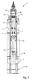
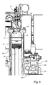
- Fig. 1 and 2 show an engine 1 according to a preferred embodiment of the invention in cross sectional view from the front and for one cylinder from the side of the engine.
- the engine 1 is a uniflow low-speed two-stroke crosshead diesel engine of the crosshead type, which may be a propulsion engine in a ship or a prime mover in a power plant. These engines have typically from 3 up to 14 cylinders in line.
- the engine 1 is built up from a bedplate 2 with the main bearings for the crankshaft 3.
- the crankshaft 3 is of the semi-built type.
- the semi-built type is made from forged or cast steel throws that are connected with the main journals by shrink fit connections.
- the bedplate 2 can be made in one part or be divided into sections of suitable size in accordance with production facilities.
- the bedplate consists of high, welded, longitudinal girders and welded cross girders with cast steel bearing supports - alternatively the bedplate can be of cast design.
- the oil pan which is integrated into the bedplate in the cast design, collects the return oil from the forced lubricating and cooling oil system.
- the connecting rod 8 is made of forged or cast steel and provided with bearing caps (for the crosshead and crankpin bearings.
- the crosshead and crankpin bearing caps are secured to the connecting rod 8 by studs and nuts which are tightened by hydraulic jacks.
- the crosshead bearing 22 consists of a set of thin-walled steel shells, lined with bearing metal.
- the crankpin bearing is provided with thin-walled steel shells, lined with bearing metal. Lubrication oil is supplied through ducts (not visible in the Figs.) in the crosshead 22 and connecting rod 8.
- the main bearings consist of thin walled steel shells lined with bearing metal.
- the bottom shell can, by means of special tools, and hydraulic tools for lifting the crankshaft, be rotated out and in.
- the shells are kept in position by a bearing cap (not shown).
- a welded design A-shaped frame box 4 is mounted on the bedplate.
- the frame box can be of cast or welded design.
- On the exhaust side it is provided with relief valves for each cylinder while, on the camshaft side, it is provided with a large hinged door for each cylinder.
- the crosshead guides are integrated in the frame box.
- a cylinder frame 5 is mounted on top of the frame box 4.
- Staybolts (not shown) connect the bedplate 2 to the cylinder frame 5 and keep the structure together.
- the staybolts are tightened with hydraulic jacks.
- the cylinder frame 5 is cast in one or more pieces with integrated camshaft housing 25, or it is a welded design.
- the camshaft housing 25 is welded/bolted thereto or integrally formed with the cylinder frame (as shown).
- the cylinder frame 5 is provided with access covers for cleaning the scavenge air space and for inspection of scavenge ports and piston rings from the camshaft side. Together with the cylinder liner 6 it forms the scavenge air space.
- the scavenge air receiver 9, is bolted with its open side to the cylinder frame 5.
- a piston rod stuffing box which is provided with sealing rings for scavenge air, and with oil scraper rings which prevent oil from coming up into the scavenge air space.
- the piston 13 includes a piston crown and piston skirt.
- the piston crown is made of heat-resistant steel and has four ring grooves which are hard-chrome plated on both the upper and lower surfaces of the grooves.
- the piston rod 14 is connected to the crosshead 22 with four screws.
- the piston rod 14 has a central bore (not visible in the drawings) which, in conjunction with a cooling oil pipe, forms the inlet and outlet for cooling oil for the piston 13.
- the crosshead 22 is of forged steel and is provided with cast steel guide shoes with white metal on the running surface.
- a telescopic pipe (not visible) for oil inlet and the pipe for oil outlet are mounted on the top of the guide shoes.
- the cylinder liners 6 are of the uniflow type and are carried by the cylinder frame 5.
- the cylinder liners 6 are made of alloyed cast iron and are suspended in the cylinder frame 5 by means of a low situated flange. The uppermost part of the liner is surrounded by cast iron cooling jacket.
- the cylinder liners 6 have scavenge ports 7 and drilled holes (not shown) for cylinder lubrication.
- the camshaft 28 is embedded in bearing shells lined with white metal in the camshaft housing 25.
- the camshaft 28 is made in one piece with, exhaust cams, indicator cams, thrust disc and chain wheel shrunk onto the shaft.
- the exhaust cams are of steel, with a hardened roller race. They can be adjusted and dismantled hydraulically.
- the cylinders 6 is of the uniflow type and has scavenge air ports 7 located in an airbox 5', which from a scavenge air receiver 9 ( Fig. 1 ), is supplied with scavenge air pressurized by a turbocharger 10 ( Fig. 1 ).
- the air intake to the turbocharger 10 takes place directly from the engine room through an intake silence (not shown) of the turbocharger. From the turbocharger 10, the air is led via a charging air pipe (not shown), air cooler (not shown) and scavenge air receiver 9 to the scavenge ports 7 of the cylinder liners 6.
- the engine is fitted with one or more turbochargers arranged on the aft end of the engine for 4-9 cylinder engines and on the exhaust side for 10 or more cylinder engines.
- the engine is provided with electrically-driven scavenge air blowers (not shown).
- the suction side of the blowers is connected to the scavenge air space after the air cooler.
- non-return valves (not shown) are fitted which automatically close when the auxiliary blowers supply the air.
- the auxiliary blowers assist the turbocharger compressor at low and medium load conditions.
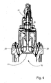
- An exhaust valve 11 as shown in greater detail in Fig. 3 is mounted centrally in the top of the cylinder in a cylinder cover 12. At the end of the expansion stroke the exhaust valve 11 opens before the engine piston 13 passes down past the scavenge air ports 7, whereby the combustion gases in the combustion chamber 15 above the piston 13 flow out through an exhaust passage 16 opening into an exhaust receiver 17 and the pressure in the combustion chamber 15 is relieved. The exhaust valve 11 closes again during the upward movement of the piston 13. The exhaust valve 11 is driven upwards by a pneumatic spring 20.
- the exhaust valve 11 is opened by means of the camshaft 28 that is disposed within a camshaft housing 25 that extends along the length of the engine adjacent to the cylinder frame 5.
- a high-pressure feed conduit 30 of the hydraulic system associated with the fuel injection system (which will be described in greater detail below) is also disposed in the camshaft housing 25.
- the feed conduit 30 extends substantially along with a whole length of the engine. Since the feed conduit 30 is disposed inside the camshaft housing, there is no need for using a double walled feed conduit 30 that is otherwise required for protecting engine operators in case the highly pressurized feed conduit 30 ruptures.
- Figs. 3 and 4 illustrate the top of the cylinder liner 6, the cylinder cover 12 and the exhaust valve housing.
- the cylinder cover 12 is of forged steel, made in one piece, and has bores for cooling water. It has a central bore for the exhaust valve 11 and bores for two or tree fuel injectors 23, a safety valve (not shown), a starting valve (not shown) and indicator valve (not shown).
- Each cylinder cover 12 is equipped with two or three fuel injectors 23, one starting valve, one safety valve, and one indicator valve.
- the opening of the fuel injectors 23 is controlled by the fuel oil high pressure created by the fuel boosters (described in further detailed below), and the fuel injector 23 is closed by a spring.
- An automatic vent slide (not shown) allows circulation of fuel oil through the fuel injector and through the high pressure pipes that connect the fuel injectors 23 to the fuel boosters, and prevents the combustion chamber 15 from being filled up with fuel oil in the event that the spindle of the injector 23 is sticking when the engine 1 is stopped. Oil from the vent slide and other drains is led away in a closed system.
- the exhaust valve housing is of cast iron and arranged for water cooling.
- the housing is provided with a bottom piece of steel with hardfacing metal welded onto the seat.
- the bottom piece is water cooled.
- the valve spindle itself is made of heat resistant steel with hardfacing metal welded onto the seat.
- the exhaust valve housing is provided with a spindle guide.
- the exhaust valve housing is tightened to the cylinder cover 12 with studs and nuts.
- a hydraulic exhaust valve actuator 21 is mounted on top of the exhaust valve housing. When pressurized, the hydraulic actuator 21 urges the exhaust valve in the downward (opening) direction.
- the hydraulic actuator 21 comprises a piston in a cylinder with a pressure chamber therein above the piston.
- the exhaust valve housing also includes an air spring 20 that urges the exhaust valve spindle 11 upward (in the closing direction).
- the air spring 20 includes a spring piston with a spring chamber disposed below the spring piston in a cylinder in the exhaust valve housing.
- each exhaust valve is connected via a pressure pipe 35 to a piston pump 37 ( Fig. 6 ).
- a piston pump 37 There is one piston pump 37 and one exhaust valve 11 per cylinder in the present embodiment, but there could be more than one piston pumps or more than one exhaust valve per cylinder (not shown).
- the piston pump 37 is mounted on a roller guide housing 46.
- the roller 42 follows the respective cam 29 on the camshaft 28.
- the piston pump 37 is thus activated by the camshaft 28.
- Fig. 5 is a perspective view of the engine with several components are removed for illustration purposes.
- the camshaft 28 is driven by a chain drive 26 that connects the camshaft 28 to the crankshaft 3.
- the chain drive 26 is provided with a chain tightener (not shown) and guide bars (not shown) to support the long chain lengths.
- the chain drive powers the hydraulic pumps (not shown) for the high-pressure hydraulics of the engine.
- the chain may also serve to drive second order counterbalance weights.
- the camshaft can be driven by a transmission with gears (not shown).
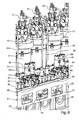
- Fig. 6 shows a section of Fig. 5 with the camshaft housing 25 and the cylinders 6 in greater detail.
- conduits 31 branch off from the feed conduit 30.
- the conduits 31 connect the feed conduit 30 to the pressure boosters 39 via distributor blocks 40 with hydraulic control valves 41.
- the distributor blocks 40 are mounted on the top plate of the camshaft housing 25.
- the piston pumps 37 that are actuated by cams 29 of the camshaft 28 are also disposed on the top plate 25' of the camshaft housing 25.
- the piston pumps 37 are connected to the hydraulic exhaust valve actuators 21 via pressure pipes 35.
- Each cylinder 6 is provided with two or three injectors23 each connected with conduits (not shown in Fig. 6 but with ref. numeral 51 in Fig. 8 ) to the port or ports of the pressure booster 39.
- Each distributor block 40 carries two proportional control valves 41 that controls the connection of the port on top of the distributor block 40 with the return conduit (65 in Fig. 8 ) and feed conduit 30 in camshaft housing 25.
- a pressure booster 39 is mounted on top of each distributor block 40 and is in communication with the port on top of the distributor block 40.
- the distributor blocks 40 serve as a mechanical support for the hydraulically activated fuel pressure booster 39.
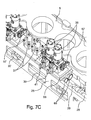
- Fig. 7A , 7C and 7C show a compression chamber housing 68 in detail in different cross-sectional views and in a perspective view.
- the compression chambers 67 provide an enlarged volume for storing potential energy in the hydraulic fluid to ensure that the necessary hydraulic oil peak flow is available during the whole fuel injection step.
- one compression chamber housing 68 with two compression chambers 67 is provided for a pair of neighboring cylinders 6.
- the compression chambers 68 are fed with a high-pressure hydraulic fluid from the feed conduit 30 via locally branched off conduits 31.
- the connection between conduits 31 and conduit 30 is realized by means of a connection block 30' that is mounted on the bottom of the camshaft housing 25.
- the compression chamber housing 68 is formed as an integral part of the top plate of the camshaft housing 25.
- the top plate of the camshaft housing 25 is longitudinally divided into sections.
- One such type of section being a metal slab with two cylindrical compression chambers 67 formed therein, the slab thereby also forming the compression chamber housing 68.
- This top plate also carries the distributor blocks 40 on top of which the pressure boosters 39 are placed.
- the longitudinal axis of the cylindrical compression chambers 67 is arranged in parallel with the longitudinal axis of the camshaft 28.
- the compression chambers 67 are manufactured by machining two parallel bores in the solid slab of metal.
- the compression chambers 67 are sealed off by circular locking plates 69 that are bolted to the compression chamber housing 68.
- Upwardly directed bores (not shown) through the compression chamber housing 68 connect to the compression chambers 67 to the distributor blocks 40. Since the distributor blocks are mounted directly on top of the compression chamber housing 68, the path that the high-pressure hydraulic fluid has to travel from the compression chambers 67 to the distributor blocks 40 is very short.
- the other type of top plate of the camshaft housing 25 (which is shown in cross-sectional view in Fig. 7 ) carries the piston pumps 37.
- the two types of camshaft housing top plates are alternatingly distributed along the length of the camshaft housing 25. There is a longitudinal overlap at the transition between the two types of top plates, and the top plates are bolted together at this overlap.
- Fig. 8 shows the fuel injection system diagrammatically.
- the fuel is delivered from the fuel delivery installation 73 to the pressure boosters 39.
- the fuel delivery installation 73 is not shown in detail in the drawings.
- the fuel delivery installation 73 is so arranged that both diesel oil and heavy fuel oil can be used.
- the fuel is led to an electrically driven supply pump by means of which a pressure of approximately 4 bar can be maintained in the low pressure part of the fuel circulating system, thus avoiding gasification of the fuel in a venting box in the temperature ranges applied.
- the fuel oil is led to an electrically-driven circulating pump, which pumps the fuel oil through a heater and a full flow filter situated immediately before the inlet to the engine 1, where the fuel is distributed to the respective pressure boosters 39.
- the fuel injection is performed by the electronically controlled pressure boosters 39 one per cylinder.
- the boosters multiply the pressure from the low-pressure (where the hydraulic fluid is applied) side to the high pressure side (the fuel side) by a fixed ratio.
- the fuel boosters 39 are powered by pressurized hydraulic fluid, which may be the engine lubrication oil.
- a pressure pump 60 delivers high pressure hydraulic fluid, typically a few hundred bar, via feed conduit 30 to the cylinders. If the hydraulic fluid is engine lubrication oil, the pressure pump 60 is not the engine lubrication pump which operates at a much lower pressure. Return fluid is transported from the cylinders via conduit 65 to the tank 61 from which the pump 60 draws its fluid.
- Compression chambers 67 are provided for each pair of cylinders (in case the engine has an odd number of cylinders, one of the cylinder may be served by a single compression chamber).
- a conduit 69 connects the compression chamber 67 to two proportional control valves 41 and to two on/off valves 55.
- gas filled membrane type accumulators are used instead of or in addition to compression chambers.
- Each cylinder 6 of the engine 1 is associated with an electronic control unit 99 which receives general synchronizing and control signals and transmits electronic control signals to the proportional control valves 41, among others, through wires 59.
- the control units 99 may also receive signals from an overall control unit (not shown) common to all the cylinders.
- the control unit 99 calculates the timing, the rate shaping and the amount of the fuel injection, in accordance with the operating conditions of the engine.
- the control unit receives information about the rotational position of the crankshaft, the rotational speed of the crank shaft (which could be derived by the control unit 99 from the rotational position signal), ambient temperature, load, temperatures of various engine fluids.
- the control units also adapt the timing of the fuel injection for reversing the engine.
- the movement of the spool in the proportional control valve 41 is controlled by the control unit 99 in a feedback control loop.
- the feedback control loop can alternatively be included in the proportional control valve 41 itself.
- the opening profile of the proportional valve 41 is matched to a desired opening profile that has been predetermined for optimal rate shaping and is stored in the control unit 99.
- the proportional control valves 41 In their rest position the proportional control valves 41 connect the pressure chamber at the low pressure side of the pressure boosted to tank.
- the control unit 99 sends a signal to start the fuel injection for a given cylinder, one of the proportional control valves 41 opens to a certain extend and connects thereby the low pressure side of the pressure booster 39 to the compression chamber 67 via conduit 69.
- the pressure in the low pressure side of the pressure booster is multiplied, typically to reach an injection pressure between approximately 400 and 1500 bar.
- a feed conduit 51 transports the high pressure fuel to the fuel injectors 23 which atomizes the fuel by injecting it in the combustion chamber 15 via its nozzles.
- the control unit 99 also controls the on/off valves 55 that control the supply of high pressure fluid to the cylinder lubricators 57. Based upon the operating conditions and on the position the crankshaft, the control unit 99 determines when and how much lubrication oil is pumped into the cylinders. In their rest position the on/off valves 55 connect the cylinder lubricators 57 to tank 61. When a given on/off valve 55 receives a signal from the control unit 99 to pump lubrication oil into a particular cylinder, the on/off valves 55 opens up to thereby connect the cylinder lubricator 57 to compression chamber 67 via conduit 69 and the cylinder lubricator will commence pumping lubrication oil into the cylinder. The control unit 99 determines the amount of lubrication oil that is pumped into the cylinder via the length of the activation of the on/off valve 55.
- Fig. 9 shows an exemplary rate shaping profile of a fuel injection step.
- the pressure rise is intentionally smooth and slow, to obtain a long period with a substantially even and high combustion pressure, which under full load is placed close to the maximum allowable combustion pressure.
- Figs. 10 and 11 show another embodiment of the invention, in which the electronic fuel injection is of the so-called common rail type.
- the fuel is kept at high pressure and the energy for the injection is stored by compressing the fuel.
- the common rail has been divided into sections 95 that are associated with two cylinders each. This arrangement has the advantage that the common rail is much better at adapting to the torsional movements of the engine 1 during engine operation that the else would deform a very long uninterrupted common rail tube and could expose it to fatigue.
- Fig. 12 shows the common rail injection system diagrammatically.
- the engine is typically operated with heavy fuel oil (HFO) (both water emulsified and non-water emulsified).
- HFO heavy fuel oil
- the emulsification takes place in a separate emulsification unit (not shown).
- the fuel for the operation of the engine is stored in a heated tank 129.
- HFO has a viscosity of 500 to 700 cSt at 50°C and cannot flow at room temperature.
- the HFO in the tank is kept at about 50°C at all times, i.e. also during engine stops.
- generator sets i.e. smaller diesel engines that provide electrical power and heat for the ship and for the main engine during stops of the main engine.
- the HFO is lead to a filter or centrifuge 130 and to a preheater 131.
- the temperature of the HFO leaving the preheater 131 is controlled in accordance with the operating status and the grade of HFO. During engine stops, when the HFO is circulated at low pressure through the hydraulic system, the temperature of the HFO is kept in the range of 45 to 60 °C. During engine operation the temperature of the HFO leaving the preheater 131, is kept between 90 and 150 °C, depending on the viscosity of the HFO.
- a sensor (not shown) measures the viscosity of the HFO just downstream of the preheater 131 (or another suitable place). The temperature of the HFO leaving the preheater 131 is typically controlled to result in a viscosity at the measuring point in the range of 10 to 20 cSt.
- a forked intermediate conduit 132 connects the preheater to both a high pressure fuel pump 133 and an auxiliary low pressure circulation pump 134.
- Non-return valves 135 are disposed in the conduits downstream of each pump to prevent back-suction.
- the high pressure fuel pump 133 is driven by gearwheel 136 on the crankshaft 3 via a gearwheel 137.
- the high pressure fuel pump 133 produces a nominal pressure of 1000 to 1500 bar, but the pressure may fluctuate between 600 and 2000 bar in dependence of the operating conditions.
- auxiliary low pressure circulation pump 134 is driven by an electric motor 138.
- a pressure of about 3 to 10 bar is delivered for circulating the HFO through the hydraulic system during engine stops.
- the common fuel rail 140 extends along all cylinders and the connections to the cylinders 6 that are not shown in Fig. 12 are symbolized by the short upward lines that extend from the common rail.
- the common rail does not need to be formed by one long tube extending along the full length of the engine. Instead, the common rail could be divided into interconnected sections that each cover a few cylinders, as shown in Fig. 10 and 11 .
- a pair of neighboring cylinders is provided with HFO through a supply conduit 141 that branches off from the common rail 140 and leads to an inlet port of the proportional control valve 125.
- the supply conduit 141 is provided with a number of fluid accumulators 142 that deliver most of the fluid volume when the proportional control valve 125 opens and are post-fed from the common rail 140 while the proportional control valve 125 is closed.
- a feed conduit 120 connects one of the two outlet ports of the proportional control valve 125 to the injectors 23 of one of the two neighboring cylinders.
- Another feed conduit 124 connects the other one of the two outlet ports of the proportional control valve 125 to the injectors 23 of the other one of the two neighboring cylinders.
- the proportional control valve 125 also has two tank ports connected to the return conduit 143 for retrun HFO.
- the proportional control valve 125 is a solenoid driven spool valve with three main positions.
- the solenoid 144 receives a control signal from control unit 99 via wire 128.
- the solenoid 44 is connected to the valve housing via insulating spacers.
- the fuel injection timing, the volume of fuel injected and the shape of the injection pattern is controlled with the proportional valve 125.
- one proportional control valve with fewer ports and only two positions is used to control the fuel injection for one cylinder.
- the proportional control valve will connect the feed conduit to the low-pressure circuit in its rest position and connect the feed conduit to the common rail in the other of its two positions.
- the flow of fuel from the common fuel rail to the injectors is controlled by an on/off type valve.
- a conventional fuel limiter 146 is placed in both feed conduits 120,124, to avoid excessive amounts of HFO entering the cylinder should the proportional control valve 125 erroneously open up too long.
- the pressure in the return line 143 is kept to an overpressure of a few bar to avoid penetration of air into the hydraulic system and to prevent the water contained in the water emulsified HFO from forming vapor bubbles.
- a pressure control valve 147 at the downstream end to the return conduit 143 ensures that a predetermined minimum overpressure is maintained in the return conduit 143.
- the overpressure in the return conduit 143 is preferably 3 to 10 bar.
- An accumulator or expansion vessel 148 is connected to the return conduit 143 to absorb pressure fluctuations that can occur when the proportional control valve 125 changes position.
- a second return conduit 149 connects the outlet port of the injectors 23 to return conduit 43. Downstream of pressure control valve 147 the return conduit 143 feeds the used HFO to the preheater 131 to complete the cycle.
- the conduits that transport the HFO from the outlet of the preheater 131 to the common rail 140 and from the common rail 40 via the proportional control valve 125 to the injectors 23 are provided with heating means symbolized by heating coils.
- the conduits can be heated along their full length by e.g. steam tracing with or electric heating elements. The heating of these conduits serves to reduce heat loss of the hot HFO when it moves downstream from the preheater.
- the temperature of the HFO in the conduits towards the injectors and hydraulic valve actuators is kept close to 150°C, depending however on the viscosity of the HFO used.
- Adjacent conduits that run parallel for part of their length, such as feed conduit 120 and feed conduit 124 can be provided with a common heating means (not shown).
- Return lines 143 and 149 are also provided with heating means of the same type as described above.
- the temperature of the HFO in the return lines is less critical and the heating means are calibrated to ensure that the temperature of the HFO does not fall below 50°C.
- circulation pump 134 (at relatively low pressures of 3 to 10 bar) to avoid air being trapped in the hydraulic system and to avoid local cooling and hardening of the HFO.
- the high-pressure conduits 35 that connect the hydraulic piston pump 37 to the valve actuator 21 can be depressurized by electronically controlled valve means (controlled by a control unit 99) for allowing the exhaust valve to commence its return stroke in advance of the return stroke timing as defined by the respective cam on the camshaft.
- the high-pressure conduits 35 that connect the hydraulic piston pump 37 to the valve actuator 21 can be selectively obstructed by electronic valve means (controlled by a control unit 99) for delaying the return stroke until after the return stroke timing as defined by the respective cam on the camshaft.
- the one or more control units 99 can be configured to control the advanced or delayed timing of the closing of the exhaust valve in relation to the operating conditions of the engine.
- the camshaft 28 is be provided with a electro hydraulic mechanism for adjusting the angular position of the camshaft 28 relative to the angular position of the crankshaft 3.
- the mechanism is controlled by said one of more control units 99 to vary the timing of the opening and closing of the exhaust valves.
Landscapes
- Engineering & Computer Science (AREA)
- Mechanical Engineering (AREA)
- General Engineering & Computer Science (AREA)
- Chemical & Material Sciences (AREA)
- Combustion & Propulsion (AREA)
- Fuel-Injection Apparatus (AREA)
- Valve Device For Special Equipments (AREA)
- Output Control And Ontrol Of Special Type Engine (AREA)
- Combustion Methods Of Internal-Combustion Engines (AREA)
- Electrical Control Of Air Or Fuel Supplied To Internal-Combustion Engine (AREA)
- Cylinder Crankcases Of Internal Combustion Engines (AREA)
Priority Applications (1)
| Application Number | Priority Date | Filing Date | Title |
|---|---|---|---|
| DE602006015007T DE602006015007D1 (de) | 2006-04-12 | 2006-04-12 | Großer Zweitakt-Kreuzkopfdieselmotor mit Gleichstromspülung |
Applications Claiming Priority (2)
| Application Number | Priority Date | Filing Date | Title |
|---|---|---|---|
| PCT/EP2006/003367 WO2007115580A1 (en) | 2006-04-12 | 2006-04-12 | Large uniflow two-stroke diesel engine of the crosshead type |
| EP06742569A EP1977106B1 (de) | 2006-04-12 | 2006-04-12 | Grosser zweitakt-kreuzkopf-dieselmotor vom gleichstromtyp |
Related Parent Applications (2)
| Application Number | Title | Priority Date | Filing Date |
|---|---|---|---|
| EP06742569.4 Division | 2006-04-12 | ||
| EP06742569A Division EP1977106B1 (de) | 2006-04-12 | 2006-04-12 | Grosser zweitakt-kreuzkopf-dieselmotor vom gleichstromtyp |
Publications (2)
| Publication Number | Publication Date |
|---|---|
| EP2071177A1 true EP2071177A1 (de) | 2009-06-17 |
| EP2071177B1 EP2071177B1 (de) | 2010-06-16 |
Family
ID=37697891
Family Applications (3)
| Application Number | Title | Priority Date | Filing Date |
|---|---|---|---|
| EP09002173A Active EP2071177B1 (de) | 2006-04-12 | 2006-04-12 | Großer Zweitakt-Kreuzkopfdieselmotor mit Gleichstromspülung |
| EP09011142A Active EP2138703B1 (de) | 2006-04-12 | 2006-04-12 | Grosser Zweitakt-Kreuzkopfdieselmotor mit Gleichstromspülung |
| EP06742569A Active EP1977106B1 (de) | 2006-04-12 | 2006-04-12 | Grosser zweitakt-kreuzkopf-dieselmotor vom gleichstromtyp |
Family Applications After (2)
| Application Number | Title | Priority Date | Filing Date |
|---|---|---|---|
| EP09011142A Active EP2138703B1 (de) | 2006-04-12 | 2006-04-12 | Grosser Zweitakt-Kreuzkopfdieselmotor mit Gleichstromspülung |
| EP06742569A Active EP1977106B1 (de) | 2006-04-12 | 2006-04-12 | Grosser zweitakt-kreuzkopf-dieselmotor vom gleichstromtyp |
Country Status (7)
| Country | Link |
|---|---|
| EP (3) | EP2071177B1 (de) |
| JP (1) | JP4597255B2 (de) |
| KR (2) | KR101195441B1 (de) |
| CN (1) | CN101415936B (de) |
| AT (3) | ATE444442T1 (de) |
| DE (3) | DE602006017128D1 (de) |
| WO (1) | WO2007115580A1 (de) |
Cited By (1)
| Publication number | Priority date | Publication date | Assignee | Title |
|---|---|---|---|---|
| WO2012016102A2 (en) * | 2010-07-30 | 2012-02-02 | Caterpillar Inc. | Large bore fuel system and fuel injector for same |
Families Citing this family (26)
| Publication number | Priority date | Publication date | Assignee | Title |
|---|---|---|---|---|
| JP4592770B2 (ja) * | 2008-02-27 | 2010-12-08 | エムエーエヌ・ディーゼル・アンド・ターボ・フィリアル・アフ・エムエーエヌ・ディーゼル・アンド・ターボ・エスイー・ティスクランド | カムシャフトを備える大型2サイクルディーゼルエンジンの可変バルブタイミング |
| JP5079916B2 (ja) * | 2008-07-14 | 2012-11-21 | エムエーエヌ・ディーゼル・アンド・ターボ・フィリアル・アフ・エムエーエヌ・ディーゼル・アンド・ターボ・エスイー・ティスクランド | 大型2サイクルディーゼルエンジンのためのカム駆動型排気弁作動システム |
| CN102341589B (zh) * | 2009-03-18 | 2013-08-28 | 曼恩柴油机涡轮公司,曼恩柴油机涡轮德国公司子公司 | 带有排气或者燃烧气体再循环的大型涡轮增压二冲程柴油发动机和用于减少NOx和碳烟排放的方法 |
| KR20110031409A (ko) * | 2009-06-16 | 2011-03-28 | 맨 디젤 앤드 터보 필리얼 아프 맨 디젤 앤드 터보 에스이 티스크랜드 | 둘 이상의 연료성분의 연료혼합에 의하여 구동되는 대형 터보차지 2-행정 디젤 엔진 |
| KR200468041Y1 (ko) | 2009-11-16 | 2013-07-24 | 현대중공업 주식회사 | 선박용 디젤기관 알파 실린더 주유시스템 일체형 부스터 유닛 |
| AT509405A1 (de) * | 2010-01-19 | 2011-08-15 | Bosch Gmbh Robert | Verfahren zum temperieren eines injektors einer einspritzung für das einspritzen von kraftstoff in den brennraum einer brennkraftmaschine |
| JP5587091B2 (ja) * | 2010-08-05 | 2014-09-10 | 株式会社ディーゼルユナイテッド | 2ストロークガス機関 |
| EP2602460B1 (de) * | 2010-08-05 | 2017-06-21 | IHI Corporation | Zweitaktmotor |
| CN101936198B (zh) * | 2010-08-06 | 2011-12-28 | 大连理工大学 | 一种凸轮供油式电液气门驱动系统 |
| JP5024477B2 (ja) * | 2010-09-08 | 2012-09-12 | 株式会社Ihi | 2サイクルエンジン |
| JP5707274B2 (ja) * | 2011-08-12 | 2015-04-22 | 株式会社Ihi | 2サイクルエンジン |
| JP5878860B2 (ja) * | 2011-12-08 | 2016-03-08 | エムエーエヌ・ディーゼル・アンド・ターボ・フィリアル・アフ・エムエーエヌ・ディーゼル・アンド・ターボ・エスイー・ティスクランド | 排気ガス浄化機能を有するターボ過給式大型2ストロークディーゼルエンジン |
| DK201200053A (en) * | 2012-01-19 | 2013-07-20 | Man Diesel & Turbo Deutschland | Flange for cylinder connection |
| ITTO20120090A1 (it) * | 2012-02-03 | 2013-08-04 | Eltek Spa | Dispositivo e/o condotto per la rilevazione del combustibile alimentato ad un motore a combustione interna |
| JP5552146B2 (ja) * | 2012-08-29 | 2014-07-16 | エムエーエヌ・ディーゼル・アンド・ターボ・フィリアル・アフ・エムエーエヌ・ディーゼル・アンド・ターボ・エスイー・ティスクランド | 大型2サイクルディーゼルエンジンのためのカム駆動型排気弁作動システム |
| CA2906235C (en) | 2013-03-14 | 2021-04-13 | Atomic Energy Of Canada Limited / Energie Atomique Du Canada Limitee | Regulator apparatus having a charging valve assembly and a flow multiplier assembly |
| JP2014101884A (ja) * | 2013-12-27 | 2014-06-05 | Diesel United:Kk | 2ストロークガス機関 |
| JP6703868B2 (ja) * | 2016-03-08 | 2020-06-03 | 三菱重工業株式会社 | 動弁装置及びクロスヘッド式内燃機関 |
| EP3219970A1 (de) * | 2016-03-17 | 2017-09-20 | Winterthur Gas & Diesel AG | Zylinder für einen längsgespülten zweitakt-grossdieselmotor sowie grossdieselmotor |
| DK179161B1 (en) | 2016-05-26 | 2017-12-18 | Man Diesel & Turbo Filial Af Man Diesel & Turbo Se Tyskland | A large two-stroke compression-ignited internal combustion engine with fuel injection system for low flashpoint fuel and a fuel valve therefore |
| DK180242B1 (da) * | 2017-06-20 | 2020-09-08 | Thorhansa Aps | Automatisk rensende drænesystem til anvendelse på totaktsmotorer |
| JP7030553B2 (ja) * | 2018-02-09 | 2022-03-07 | 株式会社ジャパンエンジンコーポレーション | 油圧駆動装置 |
| US20200200264A1 (en) * | 2018-12-19 | 2020-06-25 | GM Global Technology Operations LLC | Split oil circuit |
| JP7465634B2 (ja) * | 2019-06-14 | 2024-04-11 | 株式会社ジャパンエンジンコーポレーション | 舶用ディーゼルエンジン |
| CN112901375B (zh) * | 2021-01-29 | 2022-08-30 | 友联船厂(蛇口)有限公司 | 一种lpg燃料供应系统 |
| KR102594131B1 (ko) * | 2022-05-18 | 2023-10-26 | 주식회사 명진파워텍 | 점화플러그용 오일씨일의 불량검출장치 |
Citations (6)
| Publication number | Priority date | Publication date | Assignee | Title |
|---|---|---|---|---|
| GB1503096A (en) * | 1975-05-16 | 1978-03-08 | Karl Marx Stadt Automobilbau | Fuel injection pumping apparatus |
| FR2496170A1 (fr) * | 1980-12-16 | 1982-06-18 | Sulzer Ag | Dispositif de commande de l'alimentation en carburant d'un moteur a combustion interne |
| JPS5920560A (ja) * | 1982-07-26 | 1984-02-02 | Yanmar Diesel Engine Co Ltd | 内燃機関用ポンプノズル |
| EP0909883A1 (de) | 1997-10-14 | 1999-04-21 | Wärtsilä NSD Schweiz AG | Anordnung und Verfahren zur Ventilsteuerung einer umsteuerbaren Dieselbrennkraftmaschine |
| JPH11241660A (ja) * | 1998-02-25 | 1999-09-07 | Isuzu Motors Ltd | 燃料噴射装置のインジェクタ組付方法 |
| WO2004013487A1 (en) * | 2002-08-02 | 2004-02-12 | Wärtsilä Finland Oy | Fuel supply system |
Family Cites Families (6)
| Publication number | Priority date | Publication date | Assignee | Title |
|---|---|---|---|---|
| CH443787A (de) * | 1965-09-14 | 1967-09-15 | Sulzer Ag | Einspritzvorrichtung einer Kolbenbrennkraftmaschine |
| JPS60139006A (ja) * | 1983-12-27 | 1985-07-23 | Nec Corp | 高周波発振器 |
| JP2642833B2 (ja) * | 1992-06-10 | 1997-08-20 | 株式会社新潟鉄工所 | 油圧式吸排気弁駆動装置 |
| US5651345A (en) * | 1995-06-02 | 1997-07-29 | Caterpillar Inc. | Direct operated check HEUI injector |
| EP1171707B1 (de) * | 1999-04-16 | 2003-09-03 | Caterpillar Inc. | Pumpe mit variabler fördermenge und ihre verwendung in einem common-rail-kraftstoffeinspritzsystem |
| DE10242894A1 (de) * | 2002-09-16 | 2004-03-25 | Robert Bosch Gmbh | Kraftstoff-Einspritzsystem und Zylinderkopf mit einem zentralen Kraftstoffspeicher |
-
2006
- 2006-04-12 DE DE602006017128T patent/DE602006017128D1/de active Active
- 2006-04-12 JP JP2009503419A patent/JP4597255B2/ja active Active
- 2006-04-12 WO PCT/EP2006/003367 patent/WO2007115580A1/en active Application Filing
- 2006-04-12 DE DE602006009563T patent/DE602006009563D1/de not_active Expired - Fee Related
- 2006-04-12 DE DE602006015007T patent/DE602006015007D1/de active Active
- 2006-04-12 KR KR1020117020105A patent/KR101195441B1/ko active IP Right Grant
- 2006-04-12 AT AT06742569T patent/ATE444442T1/de not_active IP Right Cessation
- 2006-04-12 AT AT09002173T patent/ATE471451T1/de not_active IP Right Cessation
- 2006-04-12 EP EP09002173A patent/EP2071177B1/de active Active
- 2006-04-12 EP EP09011142A patent/EP2138703B1/de active Active
- 2006-04-12 CN CN2006800541928A patent/CN101415936B/zh active Active
- 2006-04-12 KR KR1020087024755A patent/KR101099675B1/ko active IP Right Grant
- 2006-04-12 AT AT09011142T patent/ATE482335T1/de not_active IP Right Cessation
- 2006-04-12 EP EP06742569A patent/EP1977106B1/de active Active
Patent Citations (6)
| Publication number | Priority date | Publication date | Assignee | Title |
|---|---|---|---|---|
| GB1503096A (en) * | 1975-05-16 | 1978-03-08 | Karl Marx Stadt Automobilbau | Fuel injection pumping apparatus |
| FR2496170A1 (fr) * | 1980-12-16 | 1982-06-18 | Sulzer Ag | Dispositif de commande de l'alimentation en carburant d'un moteur a combustion interne |
| JPS5920560A (ja) * | 1982-07-26 | 1984-02-02 | Yanmar Diesel Engine Co Ltd | 内燃機関用ポンプノズル |
| EP0909883A1 (de) | 1997-10-14 | 1999-04-21 | Wärtsilä NSD Schweiz AG | Anordnung und Verfahren zur Ventilsteuerung einer umsteuerbaren Dieselbrennkraftmaschine |
| JPH11241660A (ja) * | 1998-02-25 | 1999-09-07 | Isuzu Motors Ltd | 燃料噴射装置のインジェクタ組付方法 |
| WO2004013487A1 (en) * | 2002-08-02 | 2004-02-12 | Wärtsilä Finland Oy | Fuel supply system |
Cited By (3)
| Publication number | Priority date | Publication date | Assignee | Title |
|---|---|---|---|---|
| WO2012016102A2 (en) * | 2010-07-30 | 2012-02-02 | Caterpillar Inc. | Large bore fuel system and fuel injector for same |
| WO2012016102A3 (en) * | 2010-07-30 | 2012-04-19 | Caterpillar Inc. | Large bore fuel system and fuel injector for same |
| US8480009B2 (en) | 2010-07-30 | 2013-07-09 | Caterpillar Inc. | Large bore fuel system and fuel injector for same |
Also Published As
| Publication number | Publication date |
|---|---|
| CN101415936A (zh) | 2009-04-22 |
| JP4597255B2 (ja) | 2010-12-15 |
| EP2138703B1 (de) | 2010-09-22 |
| CN101415936B (zh) | 2011-07-27 |
| ATE471451T1 (de) | 2010-07-15 |
| EP2071177B1 (de) | 2010-06-16 |
| DE602006015007D1 (de) | 2010-07-29 |
| DE602006017128D1 (de) | 2010-11-04 |
| DE602006009563D1 (de) | 2009-11-12 |
| EP2138703A1 (de) | 2009-12-30 |
| JP2009532615A (ja) | 2009-09-10 |
| ATE482335T1 (de) | 2010-10-15 |
| KR20110112445A (ko) | 2011-10-12 |
| KR20080106343A (ko) | 2008-12-04 |
| EP1977106A1 (de) | 2008-10-08 |
| KR101195441B1 (ko) | 2012-10-30 |
| EP1977106B1 (de) | 2009-09-30 |
| KR101099675B1 (ko) | 2011-12-28 |
| WO2007115580A1 (en) | 2007-10-18 |
| ATE444442T1 (de) | 2009-10-15 |
Similar Documents
| Publication | Publication Date | Title |
|---|---|---|
| EP1977106B1 (de) | Grosser zweitakt-kreuzkopf-dieselmotor vom gleichstromtyp | |
| JP2009532615A5 (de) | ||
| JP4318266B2 (ja) | 大型2サイクルディーゼルエンジン用のカム駆動燃料噴射システム | |
| WO2006081829A1 (en) | A large two-stroke diesel engine with hydraulically actuated exhaust gas valves | |
| JP5079916B2 (ja) | 大型2サイクルディーゼルエンジンのためのカム駆動型排気弁作動システム | |
| JP4657386B2 (ja) | 電子制御式排気弁作動システムを備える大型2サイクルディーゼルエンジン | |
| KR100885456B1 (ko) | 대형 2행정 디젤 엔진용 캠 구동 배기 밸브 작동 시스템 | |
| JP2008527239A5 (de) | ||
| KR101438189B1 (ko) | 크로스헤드와 캠 구동 배기 밸브 액추에이션 시스템을 구비한 대형 저속 터보차져 2-행정 단류 내연 엔진 | |
| WO2008145151A1 (en) | Fuel injection system for large two-stroke diesel engine | |
| JP4597264B2 (ja) | クロスヘッド型大型ユニフロー式2サイクルディーゼル機関 | |
| JP5061214B2 (ja) | 油圧作動排気ガス弁を備えた大型2サイクルディーゼルエンジン | |
| JP5552146B2 (ja) | 大型2サイクルディーゼルエンジンのためのカム駆動型排気弁作動システム | |
| CN102251895B (zh) | 十字头型的大型单流式双冲程柴油发动机 | |
| CN109973272B (zh) | 一种低速柴油机 | |
| WO2009030253A1 (en) | Large two-stroke diesel engine with outwardly opening exhaust valves |
Legal Events
| Date | Code | Title | Description |
|---|---|---|---|
| PUAI | Public reference made under article 153(3) epc to a published international application that has entered the european phase |
Free format text: ORIGINAL CODE: 0009012 |
|
| 17P | Request for examination filed |
Effective date: 20090217 |
|
| AC | Divisional application: reference to earlier application |
Ref document number: 1977106 Country of ref document: EP Kind code of ref document: P |
|
| AK | Designated contracting states |
Kind code of ref document: A1 Designated state(s): AT BE BG CH CY CZ DE DK EE ES FI FR GB GR HU IE IS IT LI LT LU LV MC NL PL PT RO SE SI SK TR |
|
| AX | Request for extension of the european patent |
Extension state: AL BA HR MK YU |
|
| 17Q | First examination report despatched |
Effective date: 20090722 |
|
| GRAP | Despatch of communication of intention to grant a patent |
Free format text: ORIGINAL CODE: EPIDOSNIGR1 |
|
| GRAS | Grant fee paid |
Free format text: ORIGINAL CODE: EPIDOSNIGR3 |
|
| AKX | Designation fees paid |
Designated state(s): AT BE BG CH CY CZ DE DK EE ES FI FR GB GR HU IE IS IT LI LT LU LV MC NL PL PT RO SE SI SK TR |
|
| GRAA | (expected) grant |
Free format text: ORIGINAL CODE: 0009210 |
|
| AC | Divisional application: reference to earlier application |
Ref document number: 1977106 Country of ref document: EP Kind code of ref document: P |
|
| AK | Designated contracting states |
Kind code of ref document: B1 Designated state(s): AT BE BG CH CY CZ DE DK EE ES FI FR GB GR HU IE IS IT LI LT LU LV MC NL PL PT RO SE SI SK TR |
|
| REG | Reference to a national code |
Ref country code: CH Ref legal event code: EP |
|
| REG | Reference to a national code |
Ref country code: IE Ref legal event code: FG4D |
|
| REF | Corresponds to: |
Ref document number: 602006015007 Country of ref document: DE Date of ref document: 20100729 Kind code of ref document: P |
|
| REG | Reference to a national code |
Ref country code: CH Ref legal event code: NV Representative=s name: PATENTANWALTSBUERO DR. URS FALK Ref country code: CH Ref legal event code: PFA Owner name: MAN DIESEL & TURBO, FILIAL AF MAN DIESEL & TURBO Free format text: MAN B & W DIESEL A/S#TEGLHOLMSGADE 41#2450 COPENHAGEN SV (DK) -TRANSFER TO- MAN DIESEL & TURBO, FILIAL AF MAN DIESEL & TURBO SE, TYSKLAND#TEGLHOLMSGADE 41#2450 COPENHAGEN SV (DK) |
|
| REG | Reference to a national code |
Ref country code: NL Ref legal event code: VDEP Effective date: 20100616 |
|
| PG25 | Lapsed in a contracting state [announced via postgrant information from national office to epo] |
Ref country code: LT Free format text: LAPSE BECAUSE OF FAILURE TO SUBMIT A TRANSLATION OF THE DESCRIPTION OR TO PAY THE FEE WITHIN THE PRESCRIBED TIME-LIMIT Effective date: 20100616 Ref country code: SE Free format text: LAPSE BECAUSE OF FAILURE TO SUBMIT A TRANSLATION OF THE DESCRIPTION OR TO PAY THE FEE WITHIN THE PRESCRIBED TIME-LIMIT Effective date: 20100616 |
|
| LTIE | Lt: invalidation of european patent or patent extension |
Effective date: 20100616 |
|
| PG25 | Lapsed in a contracting state [announced via postgrant information from national office to epo] |
Ref country code: FI Free format text: LAPSE BECAUSE OF FAILURE TO SUBMIT A TRANSLATION OF THE DESCRIPTION OR TO PAY THE FEE WITHIN THE PRESCRIBED TIME-LIMIT Effective date: 20100616 Ref country code: LV Free format text: LAPSE BECAUSE OF FAILURE TO SUBMIT A TRANSLATION OF THE DESCRIPTION OR TO PAY THE FEE WITHIN THE PRESCRIBED TIME-LIMIT Effective date: 20100616 Ref country code: SI Free format text: LAPSE BECAUSE OF FAILURE TO SUBMIT A TRANSLATION OF THE DESCRIPTION OR TO PAY THE FEE WITHIN THE PRESCRIBED TIME-LIMIT Effective date: 20100616 Ref country code: AT Free format text: LAPSE BECAUSE OF FAILURE TO SUBMIT A TRANSLATION OF THE DESCRIPTION OR TO PAY THE FEE WITHIN THE PRESCRIBED TIME-LIMIT Effective date: 20100616 |
|
| PG25 | Lapsed in a contracting state [announced via postgrant information from national office to epo] |
Ref country code: CY Free format text: LAPSE BECAUSE OF FAILURE TO SUBMIT A TRANSLATION OF THE DESCRIPTION OR TO PAY THE FEE WITHIN THE PRESCRIBED TIME-LIMIT Effective date: 20100616 Ref country code: PL Free format text: LAPSE BECAUSE OF FAILURE TO SUBMIT A TRANSLATION OF THE DESCRIPTION OR TO PAY THE FEE WITHIN THE PRESCRIBED TIME-LIMIT Effective date: 20100616 |
|
| PG25 | Lapsed in a contracting state [announced via postgrant information from national office to epo] |
Ref country code: EE Free format text: LAPSE BECAUSE OF FAILURE TO SUBMIT A TRANSLATION OF THE DESCRIPTION OR TO PAY THE FEE WITHIN THE PRESCRIBED TIME-LIMIT Effective date: 20100616 Ref country code: NL Free format text: LAPSE BECAUSE OF FAILURE TO SUBMIT A TRANSLATION OF THE DESCRIPTION OR TO PAY THE FEE WITHIN THE PRESCRIBED TIME-LIMIT Effective date: 20100616 |
|
| PG25 | Lapsed in a contracting state [announced via postgrant information from national office to epo] |
Ref country code: RO Free format text: LAPSE BECAUSE OF FAILURE TO SUBMIT A TRANSLATION OF THE DESCRIPTION OR TO PAY THE FEE WITHIN THE PRESCRIBED TIME-LIMIT Effective date: 20100616 Ref country code: BE Free format text: LAPSE BECAUSE OF FAILURE TO SUBMIT A TRANSLATION OF THE DESCRIPTION OR TO PAY THE FEE WITHIN THE PRESCRIBED TIME-LIMIT Effective date: 20100616 Ref country code: PT Free format text: LAPSE BECAUSE OF FAILURE TO SUBMIT A TRANSLATION OF THE DESCRIPTION OR TO PAY THE FEE WITHIN THE PRESCRIBED TIME-LIMIT Effective date: 20101018 Ref country code: CZ Free format text: LAPSE BECAUSE OF FAILURE TO SUBMIT A TRANSLATION OF THE DESCRIPTION OR TO PAY THE FEE WITHIN THE PRESCRIBED TIME-LIMIT Effective date: 20100616 Ref country code: IS Free format text: LAPSE BECAUSE OF FAILURE TO SUBMIT A TRANSLATION OF THE DESCRIPTION OR TO PAY THE FEE WITHIN THE PRESCRIBED TIME-LIMIT Effective date: 20101016 Ref country code: SK Free format text: LAPSE BECAUSE OF FAILURE TO SUBMIT A TRANSLATION OF THE DESCRIPTION OR TO PAY THE FEE WITHIN THE PRESCRIBED TIME-LIMIT Effective date: 20100616 |
|
| PLBE | No opposition filed within time limit |
Free format text: ORIGINAL CODE: 0009261 |
|
| STAA | Information on the status of an ep patent application or granted ep patent |
Free format text: STATUS: NO OPPOSITION FILED WITHIN TIME LIMIT |
|
| PG25 | Lapsed in a contracting state [announced via postgrant information from national office to epo] |
Ref country code: DK Free format text: LAPSE BECAUSE OF FAILURE TO SUBMIT A TRANSLATION OF THE DESCRIPTION OR TO PAY THE FEE WITHIN THE PRESCRIBED TIME-LIMIT Effective date: 20100616 |
|
| 26N | No opposition filed |
Effective date: 20110317 |
|
| PG25 | Lapsed in a contracting state [announced via postgrant information from national office to epo] |
Ref country code: GR Free format text: LAPSE BECAUSE OF FAILURE TO SUBMIT A TRANSLATION OF THE DESCRIPTION OR TO PAY THE FEE WITHIN THE PRESCRIBED TIME-LIMIT Effective date: 20100917 |
|
| REG | Reference to a national code |
Ref country code: DE Ref legal event code: R097 Ref document number: 602006015007 Country of ref document: DE Effective date: 20110316 |
|
| PG25 | Lapsed in a contracting state [announced via postgrant information from national office to epo] |
Ref country code: MC Free format text: LAPSE BECAUSE OF NON-PAYMENT OF DUE FEES Effective date: 20110430 |
|
| GBPC | Gb: european patent ceased through non-payment of renewal fee |
Effective date: 20110412 |
|
| REG | Reference to a national code |
Ref country code: FR Ref legal event code: ST Effective date: 20111230 |
|
| PG25 | Lapsed in a contracting state [announced via postgrant information from national office to epo] |
Ref country code: FR Free format text: LAPSE BECAUSE OF NON-PAYMENT OF DUE FEES Effective date: 20110502 Ref country code: DE Free format text: LAPSE BECAUSE OF NON-PAYMENT OF DUE FEES Effective date: 20111101 |
|
| REG | Reference to a national code |
Ref country code: IE Ref legal event code: MM4A |
|
| PG25 | Lapsed in a contracting state [announced via postgrant information from national office to epo] |
Ref country code: GB Free format text: LAPSE BECAUSE OF NON-PAYMENT OF DUE FEES Effective date: 20110412 |
|
| REG | Reference to a national code |
Ref country code: DE Ref legal event code: R119 Ref document number: 602006015007 Country of ref document: DE Effective date: 20111101 |
|
| PG25 | Lapsed in a contracting state [announced via postgrant information from national office to epo] |
Ref country code: IE Free format text: LAPSE BECAUSE OF NON-PAYMENT OF DUE FEES Effective date: 20110412 |
|
| PG25 | Lapsed in a contracting state [announced via postgrant information from national office to epo] |
Ref country code: LU Free format text: LAPSE BECAUSE OF NON-PAYMENT OF DUE FEES Effective date: 20110412 |
|
| PG25 | Lapsed in a contracting state [announced via postgrant information from national office to epo] |
Ref country code: BG Free format text: LAPSE BECAUSE OF FAILURE TO SUBMIT A TRANSLATION OF THE DESCRIPTION OR TO PAY THE FEE WITHIN THE PRESCRIBED TIME-LIMIT Effective date: 20100916 |
|
| PG25 | Lapsed in a contracting state [announced via postgrant information from national office to epo] |
Ref country code: HU Free format text: LAPSE BECAUSE OF FAILURE TO SUBMIT A TRANSLATION OF THE DESCRIPTION OR TO PAY THE FEE WITHIN THE PRESCRIBED TIME-LIMIT Effective date: 20100616 Ref country code: ES Free format text: LAPSE BECAUSE OF FAILURE TO SUBMIT A TRANSLATION OF THE DESCRIPTION OR TO PAY THE FEE WITHIN THE PRESCRIBED TIME-LIMIT Effective date: 20100927 |
|
| REG | Reference to a national code |
Ref country code: CH Ref legal event code: PFA Owner name: MAN ENERGY SOLUTIONS, FILIAL AF MAN ENERGY SOL, DK Free format text: FORMER OWNER: MAN DIESEL AND TURBO, FILIAL AF MAN DIESEL AND TURBO SE, TYSKLAND, DK |
|
| PGFP | Annual fee paid to national office [announced via postgrant information from national office to epo] |
Ref country code: CH Payment date: 20240501 Year of fee payment: 19 |
|
| PGFP | Annual fee paid to national office [announced via postgrant information from national office to epo] |
Ref country code: IT Payment date: 20240424 Year of fee payment: 19 |
|
| PGFP | Annual fee paid to national office [announced via postgrant information from national office to epo] |
Ref country code: TR Payment date: 20240405 Year of fee payment: 19 |