EP2070666A1 - Strangschneidvorrichtung - Google Patents
Strangschneidvorrichtung Download PDFInfo
- Publication number
- EP2070666A1 EP2070666A1 EP08021151A EP08021151A EP2070666A1 EP 2070666 A1 EP2070666 A1 EP 2070666A1 EP 08021151 A EP08021151 A EP 08021151A EP 08021151 A EP08021151 A EP 08021151A EP 2070666 A1 EP2070666 A1 EP 2070666A1
- Authority
- EP
- European Patent Office
- Prior art keywords
- strand
- cutting device
- knife
- blade
- counter
- Prior art date
- Legal status (The legal status is an assumption and is not a legal conclusion. Google has not performed a legal analysis and makes no representation as to the accuracy of the status listed.)
- Granted
Links
- 241000208125 Nicotiana Species 0.000 claims description 4
- 235000002637 Nicotiana tabacum Nutrition 0.000 claims description 4
- 235000019504 cigarettes Nutrition 0.000 description 7
- 239000000463 material Substances 0.000 description 4
- 230000006641 stabilisation Effects 0.000 description 4
- 238000011105 stabilization Methods 0.000 description 4
- 229910000831 Steel Inorganic materials 0.000 description 1
- 230000001154 acute effect Effects 0.000 description 1
- 239000002131 composite material Substances 0.000 description 1
- 238000004519 manufacturing process Methods 0.000 description 1
- 238000004064 recycling Methods 0.000 description 1
- 239000003381 stabilizer Substances 0.000 description 1
- 239000010959 steel Substances 0.000 description 1
Images


Classifications
-
- B—PERFORMING OPERATIONS; TRANSPORTING
- B26—HAND CUTTING TOOLS; CUTTING; SEVERING
- B26D—CUTTING; DETAILS COMMON TO MACHINES FOR PERFORATING, PUNCHING, CUTTING-OUT, STAMPING-OUT OR SEVERING
- B26D1/00—Cutting through work characterised by the nature or movement of the cutting member or particular materials not otherwise provided for; Apparatus or machines therefor; Cutting members therefor
- B26D1/01—Cutting through work characterised by the nature or movement of the cutting member or particular materials not otherwise provided for; Apparatus or machines therefor; Cutting members therefor involving a cutting member which does not travel with the work
- B26D1/12—Cutting through work characterised by the nature or movement of the cutting member or particular materials not otherwise provided for; Apparatus or machines therefor; Cutting members therefor involving a cutting member which does not travel with the work having a cutting member moving about an axis
- B26D1/25—Cutting through work characterised by the nature or movement of the cutting member or particular materials not otherwise provided for; Apparatus or machines therefor; Cutting members therefor involving a cutting member which does not travel with the work having a cutting member moving about an axis with a non-circular cutting member
- B26D1/34—Cutting through work characterised by the nature or movement of the cutting member or particular materials not otherwise provided for; Apparatus or machines therefor; Cutting members therefor involving a cutting member which does not travel with the work having a cutting member moving about an axis with a non-circular cutting member moving about an axis parallel to the line of cut
- B26D1/38—Cutting through work characterised by the nature or movement of the cutting member or particular materials not otherwise provided for; Apparatus or machines therefor; Cutting members therefor involving a cutting member which does not travel with the work having a cutting member moving about an axis with a non-circular cutting member moving about an axis parallel to the line of cut and coacting with a fixed blade or other fixed member
-
- A—HUMAN NECESSITIES
- A24—TOBACCO; CIGARS; CIGARETTES; SIMULATED SMOKING DEVICES; SMOKERS' REQUISITES
- A24C—MACHINES FOR MAKING CIGARS OR CIGARETTES
- A24C5/00—Making cigarettes; Making tipping materials for, or attaching filters or mouthpieces to, cigars or cigarettes
- A24C5/14—Machines of the continuous-rod type
- A24C5/31—Machines of the continuous-rod type with special arrangements coming into operation during starting, slowing-down or breakdown of the machine, e.g. for diverting or breaking the continuous rod
-
- B—PERFORMING OPERATIONS; TRANSPORTING
- B26—HAND CUTTING TOOLS; CUTTING; SEVERING
- B26D—CUTTING; DETAILS COMMON TO MACHINES FOR PERFORATING, PUNCHING, CUTTING-OUT, STAMPING-OUT OR SEVERING
- B26D7/00—Details of apparatus for cutting, cutting-out, stamping-out, punching, perforating, or severing by means other than cutting
- B26D7/26—Means for mounting or adjusting the cutting member; Means for adjusting the stroke of the cutting member
- B26D2007/2692—Means for mounting or adjusting the cutting member; Means for adjusting the stroke of the cutting member the rollers or cylinders being mounted skewed
Definitions
- the invention relates to a strand cutting device of the tobacco processing industry with a rotating knife and a counter knife, which cooperate with each other.
- a corresponding strand cutting device is for example from the DE 10 2005 062 644 A1 known. From this, in particular, a cutting device is known, in which a rotating moving cutting body is provided with a cutting edge, wherein the cutting body is arranged on a first rotary body with a rotation axis. The cutting body is arranged substantially parallel to the axis of rotation of the first rotating body.
- EP 0 286 828 B1 there is known a device for deflecting and breaking a continuous cigarette rod in a cigarette manufacturing machine, wherein a bar breaking device is provided which serves to break a rod which has been deflected by a deflecting part.
- a kind of rotating propeller is provided, which serves as a rotating cutting mechanism in the EP 0 286 828 B1 is designated.
- the cutting device from the EP 0 286 828 B1 which may also be referred to as a breaking device, damages the components of the cigarette rod or cigarette rod relatively clearly. It can also wrap paper shreds arise. These are undesirable in the recycling of the shot tobacco.
- a strand cutting device of the tobacco-processing industry with a rotating knife and a counter knife, which cooperate with each other, wherein an effective range of the knife is provided with the counter knife, which runs in rotation of the knife in the longitudinal axial direction at a cutting edge of the knife.
- a strand cutting device of the tobacco processing industry with a rotating knife and a counter knife, which cooperate with each other, wherein a base of the counter knife is stationary.
- the base of the counter knife is a region of the counter knife, which is remote from the cutting edge of the counter knife.
- a knife roller is provided, on which the rotating knife is arranged.
- a cutting edge of the rotating blade and / or a cutting edge of the counter blade is arranged obliquely to a rotation axis of the knife roller.
- a hyperboloidal shear cut is thereby made possible.
- the oblique arrangement is thus preferably not only in a direction oblique to the axis of rotation of the knife roller, but also in a direction perpendicular thereto.
- the cutting edge of the rotating blade and / or the cutting edge of the counter knife is arranged both in the horizontal direction obliquely to the rotational axis of the knife roller and in the vertical direction obliquely to the axis of rotation of the knife roller.
- the angle between the cutting edge and the axis of rotation of the knife roller is preferably between 1 ° and 9 °, in particular preferably at 5 °.
- a good result can be achieved if the counter knife is flexible. In this way, in particular blockages or stagnations can be prevented.
- a particularly simple positioning of the rotating blade is possible if this is positioned by means of an eccentric device. Accordingly, a very simple and accurate positioning of the counter knife is possible when this is positioned by means of an eccentric device.
- a strand cutting device is configured such that the knife roller has at least one groove which cooperates with a strand such that the strand is conveyed and / or comminuted.
- the at least one groove on, in particular sharp, outer edge.
- sharp outer edge is to be understood in the context of the invention, in particular a discontinuity jump in the slope of the surfaces which form the edge.
- the at least one groove preferably extends longitudinally axially over substantially the entire width of the knife roller.
- two grooves are provided, which are adjacent, wherein between the two grooves, the outer edge is arranged.
- the two surfaces forming the outer edge are at an angle to each other which is pointed.
- the rotating blade rotates at a rotational speed at least as great as the strand velocity. In this way, it can not lead in particular to a jam of the discharged strand or the cut strand parts.
- At least one guide element is provided which guides a strand to the rotating blade.
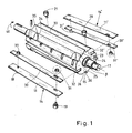
- Fig. 1 schematically shows a three-dimensional exploded view of a knife roller 15 according to the invention a strand cutting device 10, which is schematically in the Figures 2 and 3 is shown with the essential elements. For better representability because was in Fig. 1 an exploded representation chosen.
- the knife roller 15 comprises two rotating blades 11, 11 ', which are inserted in a respective corresponding groove 32, 32' of the knife roller 15.
- the rotating blades 11, 11 'attached to a rotary body, in this embodiment, the knife roller 15, and rotate with the knife roller 15, however, are fixed relative to the knife roller 15.
- a stabilization device 30, 30 ' serves to stably mount the rotating blades 11, 11' in the respective groove 32, 32 '.
- the knives 11 and 11 ' are in this embodiment on the one hand due to the orientation of the groove 32, 32' in the knife roller 15 is arranged vertically obliquely to the axis of rotation 17.
- a horizontal oblique arrangement can be provided relative to the axis of rotation 17 of the knife roller 15.
- the cutting edge 14, 14 'of the knives 11 and 11' is also in accordance with Fig. 1 to recognize.
- further grooves 23, 24 and 25 and 26 are provided which define relatively sharp edges 33, 34, 35 and 36.
- the sharp edges are formed by two respective adjacent surfaces of adjacent grooves, these surfaces having an angle ⁇ which is acute, preferably in one region between 15 ° and 60 °, more preferably in a range between 30 ° and 50 °.
- the edge 35 is defined by the intersection of a surface or wall of the groove 36 and an outer surface of the knife roller 15.
- edges which are defined by the grooves or surfaces of the knife roller 15, serve for conveying a filter strand or cigarette rod or several strands and possibly also for comminuting or pre-comminuting.
- the direction of rotation in Fig. 1 represented and provided with reference numeral 40.
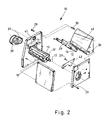
- a strand cutting device 10 according to the invention is shown schematically in three-dimensional representation in partially exploded representation.
- the knife roller 15 has the mounted blades 11 and 11 '.
- guide elements 41, 42 and 43 are provided, wherein the guide element 43 is integrated in the wall.
- the guide elements 41, 42 and 43 serve to promote strand material in the direction of the knife roller 15 and the knife 12 with its cutting edge 16.
- a drive belt 37 is shown with a drive roller 38 which is driven by a motor, not shown.
- the counter blade is arranged obliquely to the rotation axis 17 of the knife roller 15 in this embodiment and is accordingly also attached to a stabilization device 39 on the corresponding wall element, which also includes the guide element 43.
- the cutting edge 16 is also due to a corresponding one Mounting on the guide element 43 of the blade 12 obliquely opposite the axis of rotation 17 of the knife roller 15 is arranged. This results in not only an oblique arrangement of the cutting edge 16 in the horizontal direction, but also in the vertical direction. It could also be provided that the cutting edge 16 is arranged parallel to the rotation axis 17 of the knife roller 15 or is arranged obliquely only in the horizontal or only in the vertical orientation.
- Fig. 3 shows a schematic three-dimensional representation of the strand cutting device according to the invention Fig. 2 in the assembled state, wherein also a strand 27, for example, a cigarette rod or a filter strand is indicated, which moves in the direction of arrow in the strand cutting device 10.
- a strand 27 for example, a cigarette rod or a filter strand is indicated, which moves in the direction of arrow in the strand cutting device 10.
- Fig. 4 schematically shows a sectional view of the cutting region of the strand cutting device according to the invention.
- the cutting edges 14 and 16 cooperate with each other to allow a defined cut.
- the counter blade 12 is preferably flexible in this embodiment, which is achieved for example by choosing a suitable material such as a suitable steel grade and in that the free blade length I in a range of 8 to 15 times the height h, preferably in the range of 10.5 up to 12.5 times the height h is.
- Fig. 5 shows the functionality of the Scherenterrorisms or the hyperboloidal cut or chopped shred.
- the rear part of the blade 11 passes from the uppermost position to the lowest position.
- the rear part of the blade 11 is identified by the reference numeral 110.
- the front part 112 is in the moment where the rear part 110 in the upper region of the Fig. 5 is arranged, engaged with the front part 121 of the counter knife 12.
- the rear part 110 of the knife 11 and the rear part 120 of the counter knife 12 at the cutting edge in contact. It is good to see that the cutting edge is vertical both in Fig. 5 moved during the cut as well as radially.
- the hyperboloidal cut is provided with the reference numeral 50.
- the counter knife 12 is fastened with an eccentric screw 22 on a counter knife holder or the guide element 43. It can also be provided to use a normal screw instead of an eccentric screw at this point.
- the strand cutting device according to the invention is suitable for cutting cigarettes and / or filter strands of single-lane, two-lane and multi-lane strand machines, wherein all strands can be processed in a single strand cutting device.
- the oblique orientation of the cutting edge 14, 14 'of the rotating knives 11, 11' according to the invention is in particular such that it is arranged at an angle relative to a plane which is formed by the axis of rotation of the knife roller and a radial of the knife roller.
- the cutting edge of the rotating blade may additionally or alternatively be arranged radially obliquely at an angle to the axis of rotation of the knife roller.
Landscapes
- Life Sciences & Earth Sciences (AREA)
- Forests & Forestry (AREA)
- Engineering & Computer Science (AREA)
- Mechanical Engineering (AREA)
- Manufacturing Of Cigar And Cigarette Tobacco (AREA)
- Processing And Handling Of Plastics And Other Materials For Molding In General (AREA)
- Control And Other Processes For Unpacking Of Materials (AREA)
- Perforating, Stamping-Out Or Severing By Means Other Than Cutting (AREA)
Abstract
Description
- Die Erfindung betrifft eine Strangschneidvorrichtung der Tabak verarbeitenden Industrie mit einem rotierenden Messer und einem Gegenmesser, die miteinander zusammenwirken.
- Eine entsprechende Strangschneidvorrichtung ist beispielsweise aus der
DE 10 2005 062 644 A1 bekannt. Hieraus ist insbesondere eine Schneidvorrichtung bekannt, bei der ein rotierend bewegter Schneidkörper mit einer Schneidkante vorgesehen ist, wobei der Schneidkörper auf einem ersten Rotationskörper mit einer Rotationsachse angeordnet ist. Der Schneidkörper ist im Wesentlichen parallel zur Rotationsachse des ersten Rotationskörpers angeordnet. - Außerdem ist in einer weiteren Variante vorgesehen, zwei zweite Rotationskörper vorzusehen, mittels derer Strangmaterial zwischen den zwei zweiten Rotationskörpern einziehbar und anschließend abförderbar ist. Wenn nach der Inbetriebnahme einer Filterstrangmaschine die Normgeschwindigkeit erreicht wurde, wird mittels des auf dem ersten Rotationskörper angeordneten Schneidkörpers der Filterstrang abgeschnitten. Der vor Normgeschwindigkeit produzierte Strang wird durch zwei Walzen abgefördert.
- Aus
EP 0 286 828 B1 ist eine Einrichtung zum Ablenken und Abbrechen eines kontinuierlichen Zigarettenstabes in einer Zigarettenherstellungsmaschine bekannt, wobei eine Stabbrechvorrichtung vorgesehen ist, die dazu dient, einen Stab, der vom einem Ablenkteil abgelenkt wurde, durchzubrechen. Hierbei ist eine Art rotierender Propeller vorgesehen, der als drehender Schneidmechanismus in derEP 0 286 828 B1 bezeichnet ist. Die Schneidvorrichtung aus derEP 0 286 828 B1 , die auch als Brechvorrichtung bezeichnet werden kann, beschädigt die Bestandteile des Zigarettenstrangs bzw. Zigarettenstabes relativ deutlich. Es können auch Umhüllungspapierfetzen entstehen. Diese sind bei der Wiederverwertung des Schusstabaks unerwünscht. - Es ist Aufgabe der vorliegenden Erfindung, eine Strangschneidvorrichtung anzugeben, die ein Schneiden des Strangs auf schonende Weise ermöglicht, wobei ein entsprechend glatter Schnitt ermöglicht sein soll.
- Gelöst wird diese Aufgabe durch eine Strangschneidvorrichtung der Tabak verarbeitenden Industrie mit einem rotierenden Messer und einem Gegenmesser, die miteinander zusammenwirken, wobei ein Wirkbereich des Messers mit dem Gegenmesser vorgesehen ist, der bei Rotation des Messers in längsaxialer Richtung an einer Schneidkante des Messer verläuft. Durch diese erfindungsgemäße Maßnahme ergibt sich eine Art Scherschnitt, der einen sehr sauberen und glatten Schnitt ermöglicht. Hierdurch ist es ermöglicht, dass keine Papierfetzen entstehen, die die Weiterverwertung des Strangmaterials erschweren.
- Die Aufgabe wird ferner gelöst durch eine Strangschneidvorrichtung der Tabak verarbeitenden Industrie mit einem rotierenden Messer und einem Gegenmesser, die miteinander zusammenwirken, wobei eine Basis des Gegenmessers ortsfest ist. Die Basis des Gegenmessers ist ein Bereich des Gegenmessers, der abgewandt von der Schneidkante des Gegenmessers ist. Hierdurch sind auch sehr präzise und damit materialschonende Schnitte möglich.
- Vorzugsweise ist eine Messerwalze vorgesehen, an der das rotierende Messer angeordnet ist. Durch diese Maßnahme kann ein sehr gleichmäßiger Schnitt gewährleistet werden. Vorzugsweise ist eine Schneidkante des rotierenden Messers und/oder eine Schneidkante des Gegenmessers schräg zu einer Rotationsachse der Messerwalze angeordnet. Insbesondere vorzugsweise ist hierdurch ein hyperboloider Scherschnitt ermöglicht. Die schräge Anordnung ist somit vorzugsweise nicht nur in einer Richtung schräg zur Rotationsachse der Messerwalze, sondern auch noch in einer hierzu senkrechten Richtung. Bei einer horizontalen Ausrichtung der Messerwalze ist somit die Schneidkante des rotierenden Messers und/oder die Schneidkante des Gegenmessers sowohl in horizontaler Richtung schräg zur Rotationsachse der Messerwalze als auch in vertikaler Richtung schräg zur Rotationsachse der Messerwalze angeordnet. Der Winkel zwischen der Schneidkante und der Rotationsachse der Messerwalze liegt vorzugsweise zwischen 1°und 9°, insbesondere vorzugsweise bei 5°.
- Ein gutes Ergebnis ist dann erzielbar, wenn das Gegenmesser flexibel ist. Hierdurch können insbesondere Verstopfungen bzw. Stauungen verhindert werden.
- Eine besonders einfache Positionierung des rotierenden Messers ist dann möglich, wenn dieses mittels einer Exzentervorrichtung positioniert ist. Entsprechend ist eine sehr einfache und genaue Positionierung des Gegenmessers möglich, wenn dieses mittels einer Exzentervorrichtung positioniert ist.
- Besonders bevorzugt ist eine erfindungsgemäße Strangschneidvorrichtung derart ausgestaltet, dass die Messerwalze wenigstens eine Nut aufweist, die mit einem Strang derart zusammenwirkt, dass der Strang gefördert und/oder zerkleinert wird. Hierzu weist vorzugsweise die wenigstens eine Nut eine, insbesondere scharfe, Außenkante auf. Unter scharfer Außenkante ist im Rahmen der Erfindung insbesondere ein Diskontinuitätssprung in der Steigung der Flächen, die die Kante bilden, zu verstehen. Die wenigstens eine Nut erstreckt sich vorzugsweise längsaxial im Wesentlichen über die gesamte Breite der Messerwalze.
- Vorzugsweise sind zwei Nuten vorgesehen, die benachbart sind, wobei zwischen den beiden Nuten die Außenkante angeordnet ist. Vorzugsweise sind die zwei Flächen, die die Außenkante bilden, in einem Winkel zueinander angeordnet, der spitz ist.
- Vorzugsweise rotiert das rotierende Messer mit einer Rotationsgeschwindigkeit, die wenigstens so groß ist wie die Stranggeschwindigkeit. Hierdurch kann es dann auch insbesondere nicht zu einem Stau des abgeführten Strangs bzw. der abgeschnittenen Strangteile führen.
- Vorzugsweise ist wenigstens ein Leitelement vorgesehen, das einen Strang zum rotierenden Messer leitet.
- Die Erfindung wird nachstehend ohne Beschränkung des allgemeinen Erfindungsgedankens anhand von Ausführungsbeispielen unter Bezugnahme auf die Zeichnungen beschrieben, wobei bezüglich aller im Text nicht näher erläuterten erfindungsgemäßen Einzelheiten ausdrücklich auf die Zeichnungen verwiesen wird. Es zeigen:
- Fig. 1
- eine schematische dreidimensionale Darstellung einer erfindungsgemäßen Messerwalze teilweise in einer explodierten Darstellung,
- Fig. 2
- eine schematische Darstellung der erfindungsgemäßen Strangschneidvorrichtung in teilweise explodierter Darstellung,
- Fig. 3
- eine schematische Darstellung der erfindungsgemäßen Strangschneidvorrichtung aus
Fig. 2 in zusammengesetzter Darstellung, - Fig. 4
- eine schematische Schnittdarstellung eines Teils einer erfindungsgemäßen Strangschneidvorrichtung von miteinander wirkenden Messern,
- Fig. 5
- eine schematische Schnittdarstellung eines Teils einer erfindungsgemäßen Strangschneidvorrichtung in verschiedenen Positionen mit verschiedenen Drehwinkeln.
- In den folgenden Figuren sind jeweils gleiche oder gleichartige Elemente bzw. entsprechende Teile mit denselben Bezugsziffern versehen, so dass von einer entsprechenden erneuten Vorstellung abgesehen wird.
-
Fig. 1 zeigt schematisch eine dreidimensionale explodierte Darstellung einer erfindungsgemäßen Messerwalze 15 einer Strangschneidvorrichtung 10, die schematisch in denFiguren 2 und3 mit den wesentlichen Elementen dargestellt ist. Der besseren Darstellbarkeit wegen wurde inFig. 1 eine explodierte Darstellung gewählt. - Die Messerwalze 15 umfasst zwei rotierende Messer 11, 11', die in einer jeweiligen entsprechenden Nut 32, 32' der Messerwalze 15 eingebracht sind. Im Rahmen der Erfindung sind die rotierenden Messer 11, 11' an einem Rotationskörper, in diesem Ausführungsbeispiel der Messerwalze 15 angebracht, und rotieren mit der Messerwalze 15, sind allerdings relativ zur Messerwalze 15 ortsfest. Eine Stabilisationsvorrichtung 30, 30' dient zur stabilen Montage der rotierenden Messer 11, 11' in der jeweiligen Nut 32, 32'. Zur Positionierung bzw. Justage der Messer 11, 11' dienen Schrauben 18, 21 und Exzenterschrauben 19 und 20, die teilweise mit Langlöchern in den Messern 11, 11' und der Stabilisationsvorrichtung 30, 30' zusammenwirken und gegen eine jeweilige Mutter 31, 31', fixiert werden.
- Die Messer 11 und 11' sind in diesem Ausführungsbeispiel zum einen aufgrund der Ausrichtung der Nut 32, 32' in der Messerwalze 15 vertikal schräg zur Rotationsachse 17 angeordnet. Durch die Exzenterschrauben 19 und 20 kann auch eine horizontal schräge Anordnung relativ zur Rotationsachse 17 der Messerwalze 15 vorgesehen sein.
- Die Schneidkante 14, 14' der Messer 11 und 11' ist auch entsprechend in
Fig. 1 zu erkennen. Außerdem ist zu erkennen, dass am Körper der Messerwalze 15 weitere Nuten 23, 24 und 25 bzw. 26 vorgesehen sind, die relativ scharfe Kanten 33, 34, 35 und 36 definieren. Die scharfen Kanten werden durch jeweils zwei benachbarte Flächen benachbarter Nuten gebildet, wobei diese Flächen einen Winkel β aufweisen, der spitz ist, vorzugsweise in einem Bereich zwischen 15° und 60°, besonders bevorzugt in einem Bereich zwischen 30° und 50°. Die Kante 35 wird durch die Schnittlinie einer Fläche bzw. einer Wand der Nut 36 und eine Außenfläche der Messerwalze 15 definiert. Die Kanten, die durch die Nuten bzw. Flächen der Messerwalze 15 definiert sind, dienen zum Fördern eines Filterstrangs oder Zigarettenstrangs bzw. mehrerer Stränge und möglicherweise auch zum Zerkleinern bzw. Vorzerkleinern. Zur besseren Veranschaulichung ist auch die Rotationsrichtung inFig. 1 dargestellt und mit Bezugsziffer 40 versehen. - In
Fig. 2 ist eine erfindungsgemäße Strangschneidvorrichtung 10 schematisch in dreidimensionaler Darstellung in teilweiser explodierter Darstellung gezeigt. Die Messerwalze 15 weist die montierten Messer 11 und 11' auf. Es sind entsprechend einige Wandungen vorgesehen, die miteinander über Stifte 30 und Schrauben 29 verbunden werden können, wie dieses durch die strichpunktierten Linien angedeutet ist. - Es sind ferner Leitelemente 41, 42 und 43 vorgesehen, wobei das Leitelement 43 in der Wandung integriert ist. Die Leitelemente 41, 42 und 43 dienen dazu, Strangmaterial in Richtung der Messerwalze 15 bzw. des Messers 12 mit dessen Schneidkante 16 zu fördern. Zum Antrieb ist ein Antriebsriemen 37 mit einer Antriebsrolle 38 dargestellt, die durch einen nicht dargestellten Motor angetrieben wird. Das Gegenmesser ist in diesem Ausführungsbeispiel schräg zur Rotationsachse 17 der Messerwalze 15 angeordnet und wird entsprechend auch mit einer Stabilisationsvorrichtung 39 am entsprechenden Wandelement, das auch das Leitelement 43 umfasst, befestigt.
- Dadurch, dass das Leitelement 43 eine schräg angeordnete Wand aufweist, ist auch die Schneidkante 16 aufgrund einer entsprechenden Montage auf dem Leitelement 43 des Messers 12 schräg gegenüber der Rotationsachse 17 der Messerwalze 15 angeordnet. Hierdurch ergibt sich nicht nur eine schräge Anordnung der Schneidkante 16 in horizontaler Richtung, sondern auch in vertikaler Richtung. Es könnte auch vorgesehen sein, dass die Schneidkante 16 parallel zu der Rotationsachse 17 der Messerwalze 15 angeordnet ist oder nur in horizontaler bzw. nur in vertikaler Ausrichtung schräg angeordnet ist.
-
Fig. 3 zeigt in schematischer dreidimensionaler Darstellung die erfindungsgemäße Strangschneidvorrichtung ausFig. 2 in zusammengebautem Zustand, wobei auch noch ein Strang 27, beispielsweise ein Zigarettenstrang oder ein Filterstrang, angedeutet ist, der sich in Pfeilrichtung in die Strangschneidvorrichtung 10 bewegt. -
Fig. 4 zeigt schematisch eine Schnittdarstellung des Schnittbereichs der erfindungsgemäßen Strangschneidvorrichtung. Die Schneidkanten 14 und 16 wirken miteinander zusammen, um einen definierten Schnitt zu ermöglichen. Das Gegenmesser 12 ist in diesem Ausführungsbeispiel vorzugsweise flexibel, was beispielsweise durch Wahl eines geeigneten Materials wie eine geeignete Stahlsorte erreicht wird und dadurch, dass die freie Messerlänge I in einem Bereich von 8 bis 15 mal der Höhe h, bevorzugt im Bereich des 10,5 bis 12,5 fachen der Höhe h liegt. -
Fig. 5 zeigt die Funktionalität des Scherenschnitts bzw. des hyperboloiden Schnitts bzw. Häckselschnitts. Bei Drehung der Messerwalze 15 um einen Winkel α gelangt der hintere Teil des Messers 11 von der obersten Position in die unterste Position. Der hintere Teil des Messers 11 wird mit der Bezugsziffer 110 gekennzeichnet. Entsprechend ist der vordere Teil 112 in dem Moment, wo der hintere Teil 110 im oberen Bereich derFig. 5 angeordnet ist, im Eingriff mit dem vorderen Teil 121 des Gegenmessers 12. Nach Rotation der Messerwalze 15 um den Winkel α sind der hintere Teil 110 des Messers 11 und der hintere Teil 120 des Gegenmessers 12 an der Schneidkante in Kontakt. Es ist gut zu erkennen, dass sich die Schneidkante sowohl vertikal inFig. 5 während des Schnitts bewegt als auch radial. Dieses ist durch die zwei strichpunktierten Kreise der Messerwalze 15 angedeutet. Der hyperboloide Schnitt ist mit dem Bezugszeichen 50 versehen. Das Gegenmesser 12 ist mit einer Exzenterschraube 22 an einer Gegenmesserhalterung bzw. dem Leitelement 43 befestigt. Es kann auch vorgesehen sein, anstelle einer Exzenterschraube eine normale Schraube an dieser Stelle zu verwenden. - Die erfindungsgemäße Strangschneidvorrichtung eignet sich zum Zerschneiden von Zigaretten und/oder Filtersträngen von einbahnigen, zweibahnigen und mehrbahnigen Strangmaschinen, wobei sämtliche Stränge in einer einzigen Strangschneidvorrichtung verarbeitet werden können.
- Die schräge Ausrichtung der Schneidkante 14, 14' der rotierenden Messer 11, 11' ist gemäß der Erfindung insbesondere so, dass diese in einem Winkel relativ zu einer Ebene angeordnet ist, die von der Rotationsachse der Messerwalze und einer Radialen der Messerwalze gebildet wird. Außerdem kann die Schneidkante des rotierenden Messers auch zusätzlich oder alternativ radial schräg in einem Winkel zu der Rotationsachse der Messerwalze angeordnet sein.
-
- 10
- Strangschneidvorrichtung
- 11, 11'
- rotierendes Messer
- 12
- Gegenmesser
- 13
- Basis des Gegenmessers
- 14, 14'
- Schneidkante
- 15
- Messerwalze
- 16
- Schneidkante
- 17
- Rotationsachse
- 18
- Schraube
- 19
- Exzenterschraube
- 20
- Exzenterschraube
- 21
- Schraube
- 22
- Exzenterschraube
- 23
- Nut
- 24
- Nut
- 25
- Nut
- 26
- Nut
- 27
- Strang
- 28
- Gehäuse
- 29
- Schraube
- 30
- Stift
- 30, 30'
- Stabilisationsvorrichtung
- 31, 31'
- Mutter
- 32, 32'
- Nut
- 33
- Kante
- 34
- Kante
- 35
- Kante
- 36
- Kante
- 37
- Antriebsriemen
- 38
- Antriebsrolle
- 39
- Stabilisationsvorrichtung
- 40
- Rotationsrichtung
- 41
- Leitelement
- 42
- Leitelement
- 43
- Leitelement
- 50
- hyperboloider Schnitt
- 110
- hinteres Ende des Messers
- 111
- vorderes Ende des Messers
- 120
- hinteres Ende des Gegenmessers
- 121
- vorderes Ende des Gegenmessers
- α
- Winkel
- β
- Winkel
- h
- Höhe
- l
- Länge
Claims (13)
- Strangschneidvorrichtung (10) der Tabak verarbeitenden Industrie mit einem rotierenden Messer (11, 11') und einem Gegenmesser (12), die miteinander zusammenwirken, dadurch gekennzeichnet, dass ein Wirkbereich des Messers (11, 11') mit dem Gegenmesser (12) vorgesehen ist, der bei Rotation des Messers (11, 11') in längsaxialer Richtung an einer Schneidkante (14, 14') des Messer (11, 11') verläuft.
- Strangschneidvorrichtung (10) nach dem Oberbegriff des Anspruchs 1 oder nach Anspruch 1, dadurch gekennzeichnet, dass eine Basis (13) des Gegenmessers (12) ortsfest ist.
- Strangschneidvorrichtung (10) nach Anspruch 1 oder 2, dadurch gekennzeichnet, dass eine Messerwalze (15) vorgesehen ist, an der das rotierende Messer (11, 11') angeordnet ist.
- Strangschneidvorrichtung (10) nach einem der Ansprüche 1 bis 3, dadurch gekennzeichnet, dass eine Schneidkante (14, 14') des rotierenden Messers (11, 11') und/oder eine Schneidkante (16) des Gegenmessers (12) schräg zu einer Rotationsachse (17) der Messerwalze (15) angeordnet ist.
- Strangschneidvorrichtung (10) nach einem der Ansprüche 1 bis 4, dadurch gekennzeichnet, dass das Gegenmesser flexibel ist.
- Strangschneidvorrichtung (10) nach einem der Ansprüche 1 bis 5, dadurch gekennzeichnet, dass das rotierende Messer (11, 11') mittels einer Exzentervorrichtung (18 - 21) positioniert ist.
- Strangschneidvorrichtung (10) nach einem der Ansprüche 1 bis 6, dadurch gekennzeichnet, dass das Gegenmesser (12) mittels einer Exzentervorrichtung (22) positioniert ist.
- Strangschneidvorrichtung (10) nach einem der Ansprüche 3 bis 7, dadurch gekennzeichnet, dass die Messerwalze (15) wenigstens eine Nut (23 - 26) aufweist, die mit einem Strang (27) derart zusammenwirkt, dass der Strang (27) gefördert und/oder zerkleinert wird.
- Strangschneidvorrichtung (10) nach Anspruch 8, dadurch gekennzeichnet, dass die wenigstens eine Nut (23 - 26) eine scharfe Außenkante (33 - 36) aufweist.
- Strangschneidvorrichtung (10) nach Anspruch 8 oder 9, dadurch gekennzeichnet, dass die wenigstens eine Nut (23 - 26) sich längsaxial im Wesentlichen über die gesamte Breite der Messerwalze (15) erstreckt.
- Strangschneidvorrichtung (19) nach einem der Ansprüche 8 bis 10, dadurch gekennzeichnet, dass die Außenkante (33 - 36) zwischen zwei Nuten (23 - 26) angeordnet ist, wobei die zwei Flächen, die die Außenkante (33 - 36) bilden in einem Winkel β zueinander angeordnet sind, der spitz ist.
- Strangschneidvorrichtung (10) nach einem der Ansprüche 1 bis 11, dadurch gekennzeichnet, dass das rotierende Messer (11, 11') mit einer Rotationsgeschwindigkeit rotiert, die wenigstens so groß ist wie die Stranggeschwindigkeit.
- Strangschneidvorrichtung (10) nach einem der Ansprüche 1 bis 12, dadurch gekennzeichnet, dass wenigstens ein Leitelement (41, 42, 43) vorgesehen ist, das einen Strang (27) zum rotierenden Messer (11, 11') leitet.
Priority Applications (1)
| Application Number | Priority Date | Filing Date | Title |
|---|---|---|---|
| PL08021151T PL2070666T3 (pl) | 2007-12-10 | 2008-12-05 | Urządzenie do cięcia pasm |
Applications Claiming Priority (1)
| Application Number | Priority Date | Filing Date | Title |
|---|---|---|---|
| DE102007059625A DE102007059625B4 (de) | 2007-12-10 | 2007-12-10 | Strangschneidvorrichtung |
Publications (2)
| Publication Number | Publication Date |
|---|---|
| EP2070666A1 true EP2070666A1 (de) | 2009-06-17 |
| EP2070666B1 EP2070666B1 (de) | 2012-02-15 |
Family
ID=40328202
Family Applications (1)
| Application Number | Title | Priority Date | Filing Date |
|---|---|---|---|
| EP08021151A Not-in-force EP2070666B1 (de) | 2007-12-10 | 2008-12-05 | Strangschneidvorrichtung |
Country Status (6)
| Country | Link |
|---|---|
| EP (1) | EP2070666B1 (de) |
| JP (1) | JP2009136288A (de) |
| CN (1) | CN101455443B (de) |
| AT (1) | ATE545489T1 (de) |
| DE (1) | DE102007059625B4 (de) |
| PL (1) | PL2070666T3 (de) |
Cited By (2)
| Publication number | Priority date | Publication date | Assignee | Title |
|---|---|---|---|---|
| WO2014064433A1 (en) * | 2012-10-22 | 2014-05-01 | British American Tobacco (Investments) Limited | Cutting apparatus for use in the tobacco industry |
| CN112756077A (zh) * | 2020-12-29 | 2021-05-07 | 上海观道生物科技有限公司 | 药品切削机构 |
Families Citing this family (8)
| Publication number | Priority date | Publication date | Assignee | Title |
|---|---|---|---|---|
| WO2013004258A1 (de) * | 2011-07-07 | 2013-01-10 | Hauni Maschinenbau Ag | Längsfördereinrichtung für produkte der tabak verarbeitenden industrie |
| DE102012208604A1 (de) | 2012-05-23 | 2013-11-28 | Hauni Maschinenbau Ag | Einrichtung zum Schneiden von Filterstäben |
| JP7386605B2 (ja) * | 2017-11-30 | 2023-11-27 | ミュラー・マルティニ・ホルディング・アクチエンゲゼルシヤフト | ペーパーウェブの切断又は穿孔をするための装置及び方法 |
| CN108724295B (zh) * | 2018-05-16 | 2020-05-01 | 宣城市宣华食品有限公司 | 一种粉皮切割系统 |
| DE102018133156A1 (de) | 2018-12-20 | 2020-06-25 | Hauni Maschinenbau Gmbh | Herstellverfahren eines induktiv beheizbaren Tabakproduktes |
| DE102019100755A1 (de) * | 2019-01-14 | 2020-07-16 | Hauni Maschinenbau Gmbh | Vorrichtung und Verfahren zum Auftrennen einer Flachbahn sowie Vorrichtung zum Herstellen eines Strangs |
| DE102019115791A1 (de) | 2019-04-12 | 2020-10-15 | Hauni Maschinenbau Gmbh | Stabförmiger Rauchartikel mit Segmenten und einer Zwischenlage sowie Verfahren und Vorrichtung zum Anbringen einer Zwischenlage an einem Segment |
| CN115886308A (zh) * | 2022-11-16 | 2023-04-04 | 厦门烟草工业有限责任公司 | 烟草制品切割装置和卷烟机 |
Citations (6)
| Publication number | Priority date | Publication date | Assignee | Title |
|---|---|---|---|---|
| BE663042A (de) * | 1963-07-09 | 1965-08-17 | ||
| US3203292A (en) * | 1961-11-10 | 1965-08-31 | Schmermund Alfred | Cutting arrangements |
| US3733949A (en) * | 1971-06-21 | 1973-05-22 | Paper Converting Machine Co | Noise reduction strip for shear cut perforator |
| EP0286828A1 (de) * | 1987-04-17 | 1988-10-19 | SASIB S.p.A. | Vorrichtung zum Ablenken und Zerbrechen einer Stange in einer Zigarettenherstellungsmaschine |
| DE3743530A1 (de) * | 1987-12-22 | 1989-07-06 | Hauni Werke Koerber & Co Kg | Querschneider |
| DE102005062644A1 (de) | 2005-12-23 | 2007-07-26 | Hauni Maschinenbau Ag | Schneidvorrichtung und Strangmaterialabfördervorrichtung der Tabak verarbeitenden Industrie |
Family Cites Families (4)
| Publication number | Priority date | Publication date | Assignee | Title |
|---|---|---|---|---|
| FR2379260A1 (fr) * | 1977-02-03 | 1978-09-01 | Arenco Decoufle Sa Fse | Dispositif dit " casse-boudin " pour machine a confectionner les cigarettes |
| DE3641487A1 (de) * | 1986-12-04 | 1988-06-16 | Hauni Werke Koerber & Co Kg | Schneidvorrichtung zum abtrennen von abschnitten von einem bewegten materialstreifen |
| ES2051250A6 (es) * | 1991-03-26 | 1994-06-01 | Rojas Manuel Jimenez | Mejoras en el objeto de la patente principal n{ 9100972 por:"dispositivo de sujecion de flejes en cilindros de perforacion y corte para maquinaria de artes graficas. |
| EP1525960A1 (de) * | 2003-10-20 | 2005-04-27 | Müller Martini Holding AG | Schneidvorrichtung zum Schneiden einer Materialbahn |
-
2007
- 2007-12-10 DE DE102007059625A patent/DE102007059625B4/de not_active Expired - Fee Related
-
2008
- 2008-12-05 EP EP08021151A patent/EP2070666B1/de not_active Not-in-force
- 2008-12-05 AT AT08021151T patent/ATE545489T1/de active
- 2008-12-05 PL PL08021151T patent/PL2070666T3/pl unknown
- 2008-12-09 JP JP2008312907A patent/JP2009136288A/ja not_active Withdrawn
- 2008-12-10 CN CN2008101843451A patent/CN101455443B/zh not_active Expired - Fee Related
Patent Citations (7)
| Publication number | Priority date | Publication date | Assignee | Title |
|---|---|---|---|---|
| US3203292A (en) * | 1961-11-10 | 1965-08-31 | Schmermund Alfred | Cutting arrangements |
| BE663042A (de) * | 1963-07-09 | 1965-08-17 | ||
| US3733949A (en) * | 1971-06-21 | 1973-05-22 | Paper Converting Machine Co | Noise reduction strip for shear cut perforator |
| EP0286828A1 (de) * | 1987-04-17 | 1988-10-19 | SASIB S.p.A. | Vorrichtung zum Ablenken und Zerbrechen einer Stange in einer Zigarettenherstellungsmaschine |
| EP0286828B1 (de) | 1987-04-17 | 1991-10-16 | SASIB S.p.A. | Vorrichtung zum Ablenken und Zerbrechen einer Stange in einer Zigarettenherstellungsmaschine |
| DE3743530A1 (de) * | 1987-12-22 | 1989-07-06 | Hauni Werke Koerber & Co Kg | Querschneider |
| DE102005062644A1 (de) | 2005-12-23 | 2007-07-26 | Hauni Maschinenbau Ag | Schneidvorrichtung und Strangmaterialabfördervorrichtung der Tabak verarbeitenden Industrie |
Cited By (4)
| Publication number | Priority date | Publication date | Assignee | Title |
|---|---|---|---|---|
| WO2014064433A1 (en) * | 2012-10-22 | 2014-05-01 | British American Tobacco (Investments) Limited | Cutting apparatus for use in the tobacco industry |
| CN104717895A (zh) * | 2012-10-22 | 2015-06-17 | 英美烟草(投资)有限公司 | 在烟草产业中使用的切割设备 |
| US10117455B2 (en) | 2012-10-22 | 2018-11-06 | British American Tobacco (Investments) Limited | Cutting apparatus for use in the tobacco industry |
| CN112756077A (zh) * | 2020-12-29 | 2021-05-07 | 上海观道生物科技有限公司 | 药品切削机构 |
Also Published As
| Publication number | Publication date |
|---|---|
| PL2070666T3 (pl) | 2012-07-31 |
| EP2070666B1 (de) | 2012-02-15 |
| CN101455443A (zh) | 2009-06-17 |
| CN101455443B (zh) | 2013-09-18 |
| ATE545489T1 (de) | 2012-03-15 |
| DE102007059625B4 (de) | 2013-07-25 |
| DE102007059625A1 (de) | 2009-06-18 |
| JP2009136288A (ja) | 2009-06-25 |
Similar Documents
| Publication | Publication Date | Title |
|---|---|---|
| EP2070666B1 (de) | Strangschneidvorrichtung | |
| EP2848380B1 (de) | Vorrichtung zum Aufschneiden von Lebensmittelprodukten und Verfahren zum Bereitstellen von Zwischenblättern | |
| EP2399466B1 (de) | Fördertrommel der Tabak verarbeitenden Industrie | |
| DE102019108306A1 (de) | Schneidmühle zum schneidenden Zerkleinern von Proben | |
| DD201972A5 (de) | Vorrichtung zum gleichzeitigen durchtrennen von zwei fortlaufenden zigarettenstraengen | |
| DE2516111C2 (de) | Zerkleinerungsvorrichtung, insbesondere zur Verarbeitung von Papier und Kunststoffmaterial | |
| DE68912733T2 (de) | Rotierende Schneidvorrichtung. | |
| EP0387868B1 (de) | Vorrichtung zum Zerkleinern von Rest- und Abfallhölzern | |
| DE2526650A1 (de) | Zerkleinerungsaggregat | |
| EP3195934B1 (de) | Zerkleinerungsvorrichtung und verfahren zum betrieb einer solchen zerkleinerungsvorrichtung | |
| EP2140773A1 (de) | Strangmaterialabfördervorrichtung der Tabak verarbeitenden Industrie | |
| DE2830164C3 (de) | Axial-, Dresch- und Trennvorrichtung für Mähdrescher | |
| EP2759215A1 (de) | Vorrichtung und Verfahren zum Schneiden von Tabak von einem Tabakkuchen | |
| DE102018112902A1 (de) | Abstreifelement zum Abstreifen von außen an einer Hohltrommel einer Vorrichtung zum Trennen von miteinander vermischten Stoffen unterschiedlicher Fließfähigkeit anliegenden Stoffresten sowie Vorrichtung mit einem solchen Abstreifelement | |
| EP1532870A1 (de) | Vorrichtung und Verfahren zum Trennen von Tabak von einem Tabakkuchen | |
| DE102010019744A1 (de) | Vorrichtung zum Aufschneiden von Lebensmittelprodukten | |
| DE2238778A1 (de) | Papierzerkleinerungsvorrichtung | |
| DE709529C (de) | Querschneider | |
| DE8910748U1 (de) | Vorrichtung zur Drahtzerkleinerung | |
| DE3434303C2 (de) | Vorrichtung zum Zerkleinern von Abfall | |
| EP2014427B1 (de) | Verfahren und Vorrichtung zum Zertrennen von kontinuierlich geförderten Papierlagen | |
| EP0602408A1 (de) | Häcksler | |
| DE19547906C1 (de) | Vorrichtung zum Schneiden von Kautschukmaterial | |
| DE8504657U1 (de) | Vorrichtung zum Schneiden von Endlosformularen, beispielsweise von EDV-Ausdrucken | |
| DE10150026A1 (de) | Dokumentenvernichter für den crosscut-Schnitt |
Legal Events
| Date | Code | Title | Description |
|---|---|---|---|
| PUAI | Public reference made under article 153(3) epc to a published international application that has entered the european phase |
Free format text: ORIGINAL CODE: 0009012 |
|
| AK | Designated contracting states |
Kind code of ref document: A1 Designated state(s): AT BE BG CH CY CZ DE DK EE ES FI FR GB GR HR HU IE IS IT LI LT LU LV MC MT NL NO PL PT RO SE SI SK TR |
|
| AX | Request for extension of the european patent |
Extension state: AL BA MK RS |
|
| 17P | Request for examination filed |
Effective date: 20091117 |
|
| 17Q | First examination report despatched |
Effective date: 20091211 |
|
| AKX | Designation fees paid |
Designated state(s): AT BE BG CH CY CZ DE DK EE ES FI FR GB GR HR HU IE IS IT LI LT LU LV MC MT NL NO PL PT RO SE SI SK TR |
|
| GRAP | Despatch of communication of intention to grant a patent |
Free format text: ORIGINAL CODE: EPIDOSNIGR1 |
|
| GRAS | Grant fee paid |
Free format text: ORIGINAL CODE: EPIDOSNIGR3 |
|
| GRAA | (expected) grant |
Free format text: ORIGINAL CODE: 0009210 |
|
| AK | Designated contracting states |
Kind code of ref document: B1 Designated state(s): AT BE BG CH CY CZ DE DK EE ES FI FR GB GR HR HU IE IS IT LI LT LU LV MC MT NL NO PL PT RO SE SI SK TR |
|
| REG | Reference to a national code |
Ref country code: CH Ref legal event code: EP Ref country code: GB Ref legal event code: FG4D Free format text: NOT ENGLISH |
|
| REG | Reference to a national code |
Ref country code: IE Ref legal event code: FG4D Free format text: LANGUAGE OF EP DOCUMENT: GERMAN |
|
| REG | Reference to a national code |
Ref country code: AT Ref legal event code: REF Ref document number: 545489 Country of ref document: AT Kind code of ref document: T Effective date: 20120315 |
|
| REG | Reference to a national code |
Ref country code: DE Ref legal event code: R096 Ref document number: 502008006395 Country of ref document: DE Effective date: 20120412 |
|
| REG | Reference to a national code |
Ref country code: NL Ref legal event code: T3 |
|
| LTIE | Lt: invalidation of european patent or patent extension |
Effective date: 20120215 |
|
| PG25 | Lapsed in a contracting state [announced via postgrant information from national office to epo] |
Ref country code: HR Free format text: LAPSE BECAUSE OF FAILURE TO SUBMIT A TRANSLATION OF THE DESCRIPTION OR TO PAY THE FEE WITHIN THE PRESCRIBED TIME-LIMIT Effective date: 20120215 Ref country code: NO Free format text: LAPSE BECAUSE OF FAILURE TO SUBMIT A TRANSLATION OF THE DESCRIPTION OR TO PAY THE FEE WITHIN THE PRESCRIBED TIME-LIMIT Effective date: 20120515 Ref country code: IS Free format text: LAPSE BECAUSE OF FAILURE TO SUBMIT A TRANSLATION OF THE DESCRIPTION OR TO PAY THE FEE WITHIN THE PRESCRIBED TIME-LIMIT Effective date: 20120615 Ref country code: LT Free format text: LAPSE BECAUSE OF FAILURE TO SUBMIT A TRANSLATION OF THE DESCRIPTION OR TO PAY THE FEE WITHIN THE PRESCRIBED TIME-LIMIT Effective date: 20120215 |
|
| REG | Reference to a national code |
Ref country code: PL Ref legal event code: T3 |
|
| PG25 | Lapsed in a contracting state [announced via postgrant information from national office to epo] |
Ref country code: GR Free format text: LAPSE BECAUSE OF FAILURE TO SUBMIT A TRANSLATION OF THE DESCRIPTION OR TO PAY THE FEE WITHIN THE PRESCRIBED TIME-LIMIT Effective date: 20120516 Ref country code: FI Free format text: LAPSE BECAUSE OF FAILURE TO SUBMIT A TRANSLATION OF THE DESCRIPTION OR TO PAY THE FEE WITHIN THE PRESCRIBED TIME-LIMIT Effective date: 20120215 Ref country code: PT Free format text: LAPSE BECAUSE OF FAILURE TO SUBMIT A TRANSLATION OF THE DESCRIPTION OR TO PAY THE FEE WITHIN THE PRESCRIBED TIME-LIMIT Effective date: 20120615 Ref country code: LV Free format text: LAPSE BECAUSE OF FAILURE TO SUBMIT A TRANSLATION OF THE DESCRIPTION OR TO PAY THE FEE WITHIN THE PRESCRIBED TIME-LIMIT Effective date: 20120215 |
|
| REG | Reference to a national code |
Ref country code: IE Ref legal event code: FD4D |
|
| PG25 | Lapsed in a contracting state [announced via postgrant information from national office to epo] |
Ref country code: CY Free format text: LAPSE BECAUSE OF FAILURE TO SUBMIT A TRANSLATION OF THE DESCRIPTION OR TO PAY THE FEE WITHIN THE PRESCRIBED TIME-LIMIT Effective date: 20120215 |
|
| PG25 | Lapsed in a contracting state [announced via postgrant information from national office to epo] |
Ref country code: SI Free format text: LAPSE BECAUSE OF FAILURE TO SUBMIT A TRANSLATION OF THE DESCRIPTION OR TO PAY THE FEE WITHIN THE PRESCRIBED TIME-LIMIT Effective date: 20120215 Ref country code: RO Free format text: LAPSE BECAUSE OF FAILURE TO SUBMIT A TRANSLATION OF THE DESCRIPTION OR TO PAY THE FEE WITHIN THE PRESCRIBED TIME-LIMIT Effective date: 20120215 Ref country code: DK Free format text: LAPSE BECAUSE OF FAILURE TO SUBMIT A TRANSLATION OF THE DESCRIPTION OR TO PAY THE FEE WITHIN THE PRESCRIBED TIME-LIMIT Effective date: 20120215 Ref country code: IE Free format text: LAPSE BECAUSE OF FAILURE TO SUBMIT A TRANSLATION OF THE DESCRIPTION OR TO PAY THE FEE WITHIN THE PRESCRIBED TIME-LIMIT Effective date: 20120215 Ref country code: EE Free format text: LAPSE BECAUSE OF FAILURE TO SUBMIT A TRANSLATION OF THE DESCRIPTION OR TO PAY THE FEE WITHIN THE PRESCRIBED TIME-LIMIT Effective date: 20120215 Ref country code: CZ Free format text: LAPSE BECAUSE OF FAILURE TO SUBMIT A TRANSLATION OF THE DESCRIPTION OR TO PAY THE FEE WITHIN THE PRESCRIBED TIME-LIMIT Effective date: 20120215 Ref country code: SE Free format text: LAPSE BECAUSE OF FAILURE TO SUBMIT A TRANSLATION OF THE DESCRIPTION OR TO PAY THE FEE WITHIN THE PRESCRIBED TIME-LIMIT Effective date: 20120215 |
|
| PG25 | Lapsed in a contracting state [announced via postgrant information from national office to epo] |
Ref country code: SK Free format text: LAPSE BECAUSE OF FAILURE TO SUBMIT A TRANSLATION OF THE DESCRIPTION OR TO PAY THE FEE WITHIN THE PRESCRIBED TIME-LIMIT Effective date: 20120215 |
|
| PLBE | No opposition filed within time limit |
Free format text: ORIGINAL CODE: 0009261 |
|
| STAA | Information on the status of an ep patent application or granted ep patent |
Free format text: STATUS: NO OPPOSITION FILED WITHIN TIME LIMIT |
|
| 26N | No opposition filed |
Effective date: 20121116 |
|
| REG | Reference to a national code |
Ref country code: DE Ref legal event code: R097 Ref document number: 502008006395 Country of ref document: DE Effective date: 20121116 |
|
| PG25 | Lapsed in a contracting state [announced via postgrant information from national office to epo] |
Ref country code: ES Free format text: LAPSE BECAUSE OF FAILURE TO SUBMIT A TRANSLATION OF THE DESCRIPTION OR TO PAY THE FEE WITHIN THE PRESCRIBED TIME-LIMIT Effective date: 20120526 |
|
| BERE | Be: lapsed |
Owner name: HAUNI MASCHINENBAU A.G. Effective date: 20121231 |
|
| PG25 | Lapsed in a contracting state [announced via postgrant information from national office to epo] |
Ref country code: MC Free format text: LAPSE BECAUSE OF NON-PAYMENT OF DUE FEES Effective date: 20121231 Ref country code: BG Free format text: LAPSE BECAUSE OF FAILURE TO SUBMIT A TRANSLATION OF THE DESCRIPTION OR TO PAY THE FEE WITHIN THE PRESCRIBED TIME-LIMIT Effective date: 20120515 |
|
| REG | Reference to a national code |
Ref country code: CH Ref legal event code: PL |
|
| GBPC | Gb: european patent ceased through non-payment of renewal fee |
Effective date: 20121205 |
|
| REG | Reference to a national code |
Ref country code: FR Ref legal event code: ST Effective date: 20130830 |
|
| PG25 | Lapsed in a contracting state [announced via postgrant information from national office to epo] |
Ref country code: BE Free format text: LAPSE BECAUSE OF NON-PAYMENT OF DUE FEES Effective date: 20121231 |
|
| PG25 | Lapsed in a contracting state [announced via postgrant information from national office to epo] |
Ref country code: CH Free format text: LAPSE BECAUSE OF NON-PAYMENT OF DUE FEES Effective date: 20121231 Ref country code: LI Free format text: LAPSE BECAUSE OF NON-PAYMENT OF DUE FEES Effective date: 20121231 |
|
| PG25 | Lapsed in a contracting state [announced via postgrant information from national office to epo] |
Ref country code: MT Free format text: LAPSE BECAUSE OF FAILURE TO SUBMIT A TRANSLATION OF THE DESCRIPTION OR TO PAY THE FEE WITHIN THE PRESCRIBED TIME-LIMIT Effective date: 20120215 Ref country code: FR Free format text: LAPSE BECAUSE OF NON-PAYMENT OF DUE FEES Effective date: 20130102 Ref country code: GB Free format text: LAPSE BECAUSE OF NON-PAYMENT OF DUE FEES Effective date: 20121205 |
|
| PG25 | Lapsed in a contracting state [announced via postgrant information from national office to epo] |
Ref country code: TR Free format text: LAPSE BECAUSE OF FAILURE TO SUBMIT A TRANSLATION OF THE DESCRIPTION OR TO PAY THE FEE WITHIN THE PRESCRIBED TIME-LIMIT Effective date: 20120215 |
|
| PG25 | Lapsed in a contracting state [announced via postgrant information from national office to epo] |
Ref country code: LU Free format text: LAPSE BECAUSE OF NON-PAYMENT OF DUE FEES Effective date: 20121205 |
|
| PG25 | Lapsed in a contracting state [announced via postgrant information from national office to epo] |
Ref country code: HU Free format text: LAPSE BECAUSE OF FAILURE TO SUBMIT A TRANSLATION OF THE DESCRIPTION OR TO PAY THE FEE WITHIN THE PRESCRIBED TIME-LIMIT Effective date: 20081205 |
|
| REG | Reference to a national code |
Ref country code: AT Ref legal event code: MM01 Ref document number: 545489 Country of ref document: AT Kind code of ref document: T Effective date: 20131205 |
|
| PGFP | Annual fee paid to national office [announced via postgrant information from national office to epo] |
Ref country code: PL Payment date: 20141125 Year of fee payment: 7 Ref country code: NL Payment date: 20141218 Year of fee payment: 7 |
|
| PGFP | Annual fee paid to national office [announced via postgrant information from national office to epo] |
Ref country code: IT Payment date: 20141218 Year of fee payment: 7 |
|
| PGFP | Annual fee paid to national office [announced via postgrant information from national office to epo] |
Ref country code: DE Payment date: 20141222 Year of fee payment: 7 |
|
| PG25 | Lapsed in a contracting state [announced via postgrant information from national office to epo] |
Ref country code: AT Free format text: LAPSE BECAUSE OF NON-PAYMENT OF DUE FEES Effective date: 20131205 |
|
| REG | Reference to a national code |
Ref country code: DE Ref legal event code: R119 Ref document number: 502008006395 Country of ref document: DE |
|
| REG | Reference to a national code |
Ref country code: NL Ref legal event code: MM Effective date: 20160101 |
|
| PG25 | Lapsed in a contracting state [announced via postgrant information from national office to epo] |
Ref country code: DE Free format text: LAPSE BECAUSE OF NON-PAYMENT OF DUE FEES Effective date: 20160701 Ref country code: NL Free format text: LAPSE BECAUSE OF NON-PAYMENT OF DUE FEES Effective date: 20160101 |
|
| PG25 | Lapsed in a contracting state [announced via postgrant information from national office to epo] |
Ref country code: IT Free format text: LAPSE BECAUSE OF NON-PAYMENT OF DUE FEES Effective date: 20151205 |
|
| PG25 | Lapsed in a contracting state [announced via postgrant information from national office to epo] |
Ref country code: PL Free format text: LAPSE BECAUSE OF NON-PAYMENT OF DUE FEES Effective date: 20151205 |