EP2068077A1 - Burner, and combustion equipment and boiler comprising burner - Google Patents
Burner, and combustion equipment and boiler comprising burner Download PDFInfo
- Publication number
- EP2068077A1 EP2068077A1 EP07739749A EP07739749A EP2068077A1 EP 2068077 A1 EP2068077 A1 EP 2068077A1 EP 07739749 A EP07739749 A EP 07739749A EP 07739749 A EP07739749 A EP 07739749A EP 2068077 A1 EP2068077 A1 EP 2068077A1
- Authority
- EP
- European Patent Office
- Prior art keywords
- fuel
- containing fluid
- supply nozzle
- furnace
- burner
- Prior art date
- Legal status (The legal status is an assumption and is not a legal conclusion. Google has not performed a legal analysis and makes no representation as to the accuracy of the status listed.)
- Withdrawn
Links
- 238000002485 combustion reaction Methods 0.000 title claims abstract description 82
- 239000012530 fluid Substances 0.000 claims abstract description 389
- 239000000446 fuel Substances 0.000 claims abstract description 383
- 239000004449 solid propellant Substances 0.000 claims abstract description 12
- 230000002093 peripheral effect Effects 0.000 claims abstract description 6
- XLYOFNOQVPJJNP-UHFFFAOYSA-N water Substances O XLYOFNOQVPJJNP-UHFFFAOYSA-N 0.000 claims description 27
- 239000003381 stabilizer Substances 0.000 claims description 24
- 238000000638 solvent extraction Methods 0.000 claims description 14
- 230000007423 decrease Effects 0.000 claims description 5
- 230000007480 spreading Effects 0.000 claims description 5
- 239000007788 liquid Substances 0.000 claims description 3
- 238000004804 winding Methods 0.000 claims description 2
- 239000000567 combustion gas Substances 0.000 abstract description 23
- 230000002265 prevention Effects 0.000 abstract 2
- 238000009877 rendering Methods 0.000 abstract 1
- MWUXSHHQAYIFBG-UHFFFAOYSA-N Nitric oxide Chemical compound O=[N] MWUXSHHQAYIFBG-UHFFFAOYSA-N 0.000 description 90
- 230000000694 effects Effects 0.000 description 21
- 230000001603 reducing effect Effects 0.000 description 20
- 230000009467 reduction Effects 0.000 description 17
- 230000006872 improvement Effects 0.000 description 16
- 239000007789 gas Substances 0.000 description 13
- 239000006185 dispersion Substances 0.000 description 8
- 230000001737 promoting effect Effects 0.000 description 7
- 230000008859 change Effects 0.000 description 5
- 230000001629 suppression Effects 0.000 description 5
- 238000010586 diagram Methods 0.000 description 4
- 238000010304 firing Methods 0.000 description 4
- 230000014759 maintenance of location Effects 0.000 description 4
- 238000011144 upstream manufacturing Methods 0.000 description 4
- 230000003247 decreasing effect Effects 0.000 description 3
- 230000008021 deposition Effects 0.000 description 3
- 238000010438 heat treatment Methods 0.000 description 3
- 230000000903 blocking effect Effects 0.000 description 2
- 239000003245 coal Substances 0.000 description 2
- 239000002028 Biomass Substances 0.000 description 1
- 230000032798 delamination Effects 0.000 description 1
- 238000009434 installation Methods 0.000 description 1
- 238000000034 method Methods 0.000 description 1
- 230000005855 radiation Effects 0.000 description 1
Images


Classifications
-
- F—MECHANICAL ENGINEERING; LIGHTING; HEATING; WEAPONS; BLASTING
- F23—COMBUSTION APPARATUS; COMBUSTION PROCESSES
- F23D—BURNERS
- F23D1/00—Burners for combustion of pulverulent fuel
- F23D1/005—Burners for combustion of pulverulent fuel burning a mixture of pulverulent fuel delivered as a slurry, i.e. comprising a carrying liquid
-
- F—MECHANICAL ENGINEERING; LIGHTING; HEATING; WEAPONS; BLASTING
- F23—COMBUSTION APPARATUS; COMBUSTION PROCESSES
- F23D—BURNERS
- F23D1/00—Burners for combustion of pulverulent fuel
-
- F—MECHANICAL ENGINEERING; LIGHTING; HEATING; WEAPONS; BLASTING
- F22—STEAM GENERATION
- F22B—METHODS OF STEAM GENERATION; STEAM BOILERS
- F22B1/00—Methods of steam generation characterised by form of heating method
- F22B1/02—Methods of steam generation characterised by form of heating method by exploitation of the heat content of hot heat carriers
- F22B1/18—Methods of steam generation characterised by form of heating method by exploitation of the heat content of hot heat carriers the heat carrier being a hot gas, e.g. waste gas such as exhaust gas of internal-combustion engines
- F22B1/1869—Hot gas water tube boilers not provided for in F22B1/1807 - F22B1/1861
-
- F—MECHANICAL ENGINEERING; LIGHTING; HEATING; WEAPONS; BLASTING
- F22—STEAM GENERATION
- F22B—METHODS OF STEAM GENERATION; STEAM BOILERS
- F22B21/00—Water-tube boilers of vertical or steeply-inclined type, i.e. the water-tube sets being arranged vertically or substantially vertically
- F22B21/22—Water-tube boilers of vertical or steeply-inclined type, i.e. the water-tube sets being arranged vertically or substantially vertically built-up from water tubes of form other than straight or substantially straight
- F22B21/26—Water-tube boilers of vertical or steeply-inclined type, i.e. the water-tube sets being arranged vertically or substantially vertically built-up from water tubes of form other than straight or substantially straight bent helically, i.e. coiled
-
- F—MECHANICAL ENGINEERING; LIGHTING; HEATING; WEAPONS; BLASTING
- F23—COMBUSTION APPARATUS; COMBUSTION PROCESSES
- F23C—METHODS OR APPARATUS FOR COMBUSTION USING FLUID FUEL OR SOLID FUEL SUSPENDED IN A CARRIER GAS OR AIR
- F23C99/00—Subject-matter not provided for in other groups of this subclass
-
- F—MECHANICAL ENGINEERING; LIGHTING; HEATING; WEAPONS; BLASTING
- F23—COMBUSTION APPARATUS; COMBUSTION PROCESSES
- F23D—BURNERS
- F23D2201/00—Burners adapted for particulate solid or pulverulent fuels
- F23D2201/10—Nozzle tips
-
- F—MECHANICAL ENGINEERING; LIGHTING; HEATING; WEAPONS; BLASTING
- F23—COMBUSTION APPARATUS; COMBUSTION PROCESSES
- F23D—BURNERS
- F23D2201/00—Burners adapted for particulate solid or pulverulent fuels
- F23D2201/20—Fuel flow guiding devices
Definitions
- the present invention relates to a burner and a combustion equipment and a boiler including the burner, and particularly relates to a burner capable of performing low nitrogen oxide (NOx) combustion at high efficiency.
- NOx nitrogen oxide
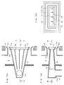
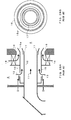
- FIG. 28 shows an example of a solid fuel (pulverized coal, biomass fuel, etc.) burner according to a conventional art.
- FIG. 28A is a side sectional view of the burner
- FIG. 28B is a front view of the burner as viewed from a furnace (4) side.
- the solid fuel burner includes a fuel-containing fluid supply nozzle (12), defining a fuel-containing fluid flow passage through which a fuel-containing fluid (11), containing a solid fuel and a conveying primary air, flows toward the furnace (4), and a combustion air sleeve (15) disposed at an outer periphery of the fuel-containing fluid supply nozzle (12), and air inside a windbox (3) is supplied as a secondary air (13) and a tertiary air (14) through a combustion air flow passage defined by the sleeve (15).
- a flame stabilizer (17) is disposed at a front end of the fuel-containing fluid supply nozzle (12), and ignition of the fuel from a vicinity of the burner is enabled by an effect of a circular vortex formed at a wake of the flame stabilizer (17).
- a front end of the combustion air sleeve (15) is disposed at a position facing a burner throat (16), a combustion air guide plate (15a), spreading outside the burner, is disposed at the front end of the sleeve (15), the tertiary air (14) is spread outward by the combustion air guide plate (15a) to delay mixing of air into a central part of a flame, and by promotion of combustion under a reducing atmosphere condition of insufficient air, generation of nitrogen oxides (NOx) in a combustion gas is suppressed.
- NOx nitrogen oxides
- FIG. 1C is a sectional view taken in a direction along an ejection flow of the fuel-containing fluid (11) at the fuel-containing fluid supply nozzle (12) in the burner of the conventional art, and as shown in FIG. 1D , which is a front view of an outlet part of the fuel-containing fluid supply nozzle (12) of the burner in FIG. 1C as viewed from the furnace (4) side, with the burner of the conventional art, a cross section of the outlet part of the fuel-containing fluid supply nozzle (12) has a shape close to a circular shape.
- FIG. 29A is a sectional view taken in a direction along the ejection flow of the fuel-containing fluid (11) at the fuel-containing fluid supply nozzle (12) in the burner of the conventional art, and an ignition position (33) of the fuel in the fuel-containing fluid ejected from the fuel-containing fluid supply nozzle (12) into the furnace (4) is formed as shown in FIG. 29B , which is a front view of the outlet part of the fuel-containing fluid supply nozzle (12) as viewed from the furnace (4) side.
- FIG. 29B is a front view of the outlet part of the fuel-containing fluid supply nozzle (12) as viewed from the furnace (4) side.
- FIG. 30 schematically shows a propagation behavior of the flame inside the furnace (4) in a cross-sectional direction along the ejection flow of the fuel-containing fluid (11) at the fuel-containing fluid supply nozzle (12) in the burner of the conventional art.
- An ignited region (32) is formed around an unignited region (31) of conical shape.
- the burner of circular cross section shown in FIGS. 28 to 30 , is frequently used in a so-called opposed firing configuration in which the burners is disposed at each of a pair of opposing furnace walls.
- so-called tangential firing in which the fuel is combusted while the fuel-containing fluid is ejected into the furnace (4) in directions of applying a rotation along a furnace wall surface from outlets of a plurality of fuel-containing fluid supply nozzles (12), an outlet shape of a transverse section (section orthogonal to the flow of the fuel-containing fluid) of each fuel-containing fluid supply nozzle (12) is made a square shape or a rectangular shape close to a square shape in many cases.
- Burners with which the outlet shape of the transverse section (section orthogonal to the flow of the fuel-containing fluid) of the fuel-containing fluid supply nozzle (12) is made a rectangular shape, an elliptical shape, or a substantially elliptical shape with major and minor axis parts, are disclosed in the following Patent Documents 1 to 3.
- a cross section of an outlet part of a fuel-containing fluid supply nozzle (12) of a burner has a shape close to a circular shape or a square shape, and there are cases where, as shown in FIG. 30 , a flame ignited at an outer side of a fuel-containing fluid ejection flow in a furnace (4) must propagate a considerable distance to reach a central part of the fuel-containing fluid ejection flow.
- a distance in a fuel-containing fluid (11) ejection flow direction from the fuel-containing fluid supply nozzle (12) that is required for the ignited flame to propagate to the central part of the fuel ejection flow in other words, an unignited distance L1' shown in FIG.
- an unignited region (31) is more expanded the larger a diameter or a peripheral part of the fuel-containing fluid supply nozzle (12).
- promotion of combustion in a reducing region in a vicinity of the burner is important for suppressing NOx generation in a combustion gas
- expansion of the unignited region (31) inhibits the NOx concentration suppression characteristic. Expansion of the unignited region (31) also means that a combustion time after ignition is short and causes lowering of combustion efficiency.
- An object of the present invention is to provide a solid fuel burner that is increased in capacity over the conventional art and yet is suppressed in expansion of an unignited region to prevent increase of NOx concentration in a combustion gas and prevent lowering of combustion efficiency, a combustion equipment and a boiler including the burner.
- a first aspect of the present invention provides a burner including: a fuel-containing fluid supply nozzle (12) supplying a fuel-containing fluid (11), containing a solid fuel and a medium for transfer of the solid fuel, to an outlet part disposed on a wall surface of a furnace (4) from a connecting part (10a) of a fuel-containing fluid transfer flow passage (10) that transfers the fluid (11); and one or more air supply nozzles (15) supplying combustion air and disposed at an outer peripheral part of the fuel-containing fluid supply nozzle (12); and where, from the connecting part (10a) of the fluid transfer flow passage (10) toward the outlet part disposed on the wall surface of the furnace (4), a cross section of the fuel-containing fluid supply nozzle (12) perpendicular to a flow of the fluid (11) has a rectangular, elliptical, or substantially elliptical shape with major and minor axis parts and, from the connecting part (10a) of the fluid transfer flow passage (10) toward the outlet part, a size of the major axis part of the cross
- a second aspect of the present invention provides the burner according to the first aspect where the fuel-containing fluid supply nozzle (12) has a configuration such that, from the connecting part (10a) of the fluid transfer flow passage (10) toward the outlet part, the size of the major axis part of the cross section perpendicular to the flow of the fluid (11) increases gradually along the direction of the flow of the fluid (11) and a size of the minor axis part is unchanged.
- a third aspect of the present invention provides the burner according to the first aspect where the fuel-containing fluid supply nozzle (12) has a configuration such that, from the connecting part (10a) of the fluid transfer flow passage (10) toward the outlet part, the size of the major axis part of the cross section perpendicular to the flow of the fluid (11) increases gradually along the direction of the flow of the fluid (11) and a size of the minor axis part decreases gradually along the direction of the flow of the fluid (11).
- a fourth aspect of the present invention provides the burner according to any of the first to third aspects where the fuel-containing fluid supply nozzle (12) has, in an interior thereof, fuel-containing fluid guide plates (19) plurally partitioning the flow of the fuel-containing fluid (11).
- a fifth aspect of the present invention provides the burner according to the fourth aspect where the fuel-containing fluid guide plates (19) are disposed at a plurality of different inclination angles with respect to a plane passing along a line extending a central axis in the direction of the flow of the fluid (11) in the fuel-containing fluid supply nozzle (12) toward the furnace (4) and parallel to a shortest axis of the minor axis part of the nozzle (12).
- a sixth aspect of the present invention provides the burner according to any of the first to fifth aspects where the fuel-containing fluid supply nozzle (12) has, in an interior of the outlet thereof, fuel-containing fluid direction changing guide plates (21) forcibly changing a direction of ejection flow of the fuel-containing fluid (11).
- a seventh aspect of the present invention provides the burner according to the sixth aspect where the fuel-containing fluid direction changing guide plates (21) are disposed in a plurality of mutually different directions with respect to a plane passing along the line extending the central axis of the fuel-containing fluid supply nozzle (12) toward the furnace (4) and parallel to a longest axis of the major axis part of the nozzle (12).
- An eighth aspect of the present invention provides the burner according to the sixth aspect where the fuel-containing fluid direction changing guide plates (21) for a portion of the fuel-containing fluid (11) are disposed parallel to the plane passing along the line extending the central axis of the fuel-containing fluid supply nozzle (12) toward the furnace (4) and parallel to the longest axis of the major axis part of the nozzle (12), and the fuel-containing fluid direction changing guide plates (21) for another portion of the fuel containing fluid (11) are disposed at an inclination angle with respect to the plane passing along the line extending the central axis of the fuel-containing fluid supply nozzle (12) toward the furnace (4) and parallel to the longest axis of the major axis part of the nozzle (12).
- a ninth aspect of the present invention provides the burner according to the fourth aspect where the fuel-containing fluid supply nozzle (12) is partitioned into a plurality of flow passages by the fuel-containing fluid guide plates (19), and central axes of the respective flow passages are disposed at the wall surface of the furnace (4) at a plurality of mutually different inclination angles with respect to the plane passing along the line extending the central axis of the fuel-containing fluid supply nozzle (12) toward the furnace (4) and parallel to the longest axis of the major axis part of the nozzle (12) outlet.
- a tenth aspect of the present invention provides the burner according to any of the first to ninth aspects where fuel-containing fluid partitioning plates (22), capable of plurally partitioning the outlet part of the fuel-containing fluid supply nozzle (12), are disposed at the outlet part.
- An eleventh aspect of the present invention provides the burner according to any of the first to tenth aspects where a flame stabilizer (17) with an L-shaped cross section is disposed at the outlet part of the fuel-containing fluid supply nozzle (12).
- a twelfth aspect of the present invention provides the burner according to the eleventh aspect where a guide plate (17a) outwardly changing an ejection direction of the combustion air in a periphery of the flame stabilizer (17) is disposed at a front end of the L-shaped flame stabilizer (17).
- a thirteenth aspect of the present invention provides the burner according to any of the first to twelfth aspects where a combustion air guide plate (15a), outwardly spreading the ejection direction of the combustion air at an outer side of the one or more combustion air supply nozzles (15) disposed at the outer peripheral part of the nozzle (12) with respect to a fuel ejection direction, is disposed at a front end of the fuel-containing fluid supply nozzle (12).
- a fourteenth aspect of the present invention provides the burner according to any one of the first to thirteenth aspects where a condenser (23), narrowing the flow passage of the fuel-containing fluid (11) once and then expanding the flow passage again, is disposed in an interior of the fuel-containing fluid supply nozzle (12).
- a fifteenth aspect of the present invention provides the burner according to any one of the first to fourteenth aspects where a fluid distribution plate (24) distributing the fuel uniformly inside the fuel-containing fluid supply nozzle (12) is disposed at an inlet part of the fuel-containing fluid supply nozzle (12).
- a sixteenth aspect of the present invention provides the burner according to any of the first to fifteenth aspects where a nozzle (41, 44), ejecting a liquid fuel or a gas fuel that is an auxiliary fuel to a vicinity of the fluid (11) ejected from the fuel-containing fluid supply nozzle (12), is disposed at the vicinity of the fuel-containing fluid supply nozzle (12).
- a seventeenth aspect of the present invention provides a combustion equipment where the burners according to any of the first to sixteenth aspects are disposed in a plurality of stages in an up/down direction at each of two opposing furnace walls, and a plurality of burners disposed at each stage are disposed respectively symmetrically in wall surface regions divided in two at a central part of width in a horizontal direction of the same furnace wall.
- An eighteenth aspect of the present invention provides a combustion equipment where the burners according to any of the first to sixteenth aspects are disposed in the plurality of stages in the up/down direction at each of the two opposing furnace walls, and burners, which, among the plurality of burners disposed in each stage of the same furnace wall, are adjacent each other in the horizontal direction, are burners of the same structure.
- a nineteenth aspect of the present invention provides a boiler including: a furnace wall formed by spirally winding a set of water wall tubes (25) inclined with respect to a horizontal direction; and where openings (26) of rectangular, elliptical, or substantially elliptical shape are disposed in the furnace wall along a longitudinal direction of the water wall tubes (25) and the burner according to any of the first to sixteenth aspects is mounted in each opening (26).
- a twentieth aspect of the present invention provides a boiler including: a furnace wall formed by a set of water wall tubes (25) extending in a vertical direction; and where openings (26) of rectangular, elliptical, or substantially elliptical shape are disposed in the furnace wall along a longitudinal direction of the water wall tubes (25) and the burner according to any of the first to sixteenth aspects is mounted in each opening (26).
- expansion of an unignited region can be suppressed even if a burner capacity is increased, an unignited distance can be reduced effectively in comparison with the conventional art because the fuel-containing fluid (11) spreads in the width direction even after the fuel-containing fluid (11) is loaded into the furnace (4) so that a cross-sectional area of the ejection flow of the fuel-containing fluid (11) increases and a flow velocity decreases, and also because the fuel-containing fluid (11) spreads inside the furnace (4), a combustion space can be utilized effectively and a practical furnace retention time is made long, thereby providing effects of reducing NOx concentration in a combustion gas and improving combustion efficiency.
- the size of the minor axis part is unchanged and this is effective for simplification of structure.
- the flow velocity at an upstream side of the fuel-containing fluid supply nozzle (12) can be made high and this is effective for preventing backfiring in a case of a readily ignitable fuel, etc.
- the increase of the flow velocity of the fuel-containing fluid (11) from the fuel-containing fluid connecting part (10a) toward the outlet part of the fuel-containing fluid supply nozzle (12) can be suppressed to minimize pressure loss and suppress wear of component parts inside the fuel-containing fluid supply nozzle (12).
- the fuel-containing fluid (11) is partitioned plurally by the fuel-containing fluid guide plates (19) in the interior of the fuel-containing fluid supply nozzle (12), the fuel-containing fluid (11) is supplied uniformly in the direction in which the fuel-containing fluid supply nozzle (12) expands from the fuel-containing fluid connecting part (10a) toward the outlet part of the nozzle (12), and the effects of NOx reduction, improvement in combustion efficiency, suppression of flow velocity increase, minimization of pressure loss, and suppression of wear of component parts are improved in comparison with other those of the third aspect of the present invention.
- the fuel-containing fluid guide plates (19) are respectively disposed in mutually opposing directions with respect to the plane passing along the line extending the central axis of the fuel-containing fluid supply nozzle (12) toward the furnace (4) and parallel to the longest axis of the major axis part of the nozzle (12), the fuel-containing fluid (11) can be ejected into the furnace (4) in two or more groups and the fuel-containing fluid ejection flow (20) can thereby be divided into groups by a simple structure to provide the effects of promoting the dispersion of the fuel-containing fluid ejection flow (20) inside the furnace (4) and promoting the combustion at the wake part of the furnace (4).
- the eighth aspect of the present invention by dividing four fuel-containing fluid ejection flows (20), formed by the fuel-containing fluid supply nozzle (12) and the fuel-containing fluid guide plates (19) into two groups (20a, 20b) and thereby making, for example, fuel-containing fluid ejection flows (20a), adjacent a furnace side wall, rectilinear flows and making fuel-containing fluid ejection flows (20b), not adjacent the furnace side wall, be ejected upon applying an inclination with respect to a horizontal direction, an effect of preventing ash deposition by suppressing flame inflow to a vicinity of the furnace side wall while maintaining promotion of combustion at the furnace wake part by dispersion of the fuel is provided.
- the fuel-containing fluid (11) can be ejected into the furnace (4) at mutually different angles with respect to the horizontal direction or the vertical direction from the fuel-containing fluid supply nozzle (12) and the fuel-containing fluid ejection flow (20) can be varied in direction without using parts inside the fuel-containing fluid supply nozzle (12) with which pulverized coal or other solid fuel collides directly, wear of parts can be suppressed effectively.
- the fuel-containing fluid ejection flow (20) is partitioned by the fuel-containing fluid partitioning plates (22) to be increased in surface area, and radiant heat inside the furnace (4) is thereby increased and a negative pressure region is formed at the wake side of the fluid partitioning plates (22), thereby making a high temperature gas in a periphery flow into the negative pressure region to contribute to early ignition of the fuel, promote combustion at a reducing region in the vicinity of the burner, and effectively contribute to the reduction of the NOx concentration in the combustion gas and the improvement in the combustion efficiency.
- the eleventh aspect of the present invention by disposing the flame stabilizer (17) with the L-shaped cross section at the outlet part of the fuel-containing fluid supply nozzle (12), a circular vortex is formed at the wake of the flame stabilizer (17) and draws back the high-temperature combustion gas to a vicinity of the flame stabilizer (17) to contribute to early ignition of the fuel, promote combustion at the reducing region in the vicinity of the burner, and effectively contribute to the reduction of the NOx concentration in the combustion gas and the improvement in the combustion efficiency in compassion with the eleventh aspect of the invention.
- the secondary air guide plate (17a) at the front end of the flame stabilizer (17) of L-shaped cross section by the secondary air guide plate (17a) at the front end of the flame stabilizer (17) of L-shaped cross section, the secondary air is spread outward and the circular vortex at the wake of the flame stabilizer (17) is enlarged, thereby increasing a recirculation amount of the high-temperature combustion gas to further quicken ignition of the fuel, promote combustion at the reducing region near the burner, and effectively contribute to the reduction of the NOx concentration in the combustion gas and the improvement in the combustion efficiency in comparison with the eleventh aspect of the invention.
- the combustion air guide plate (15a) that spreads the combustion air ejection direction at the outer side of the combustion air supply nozzles (15) outward with respect to the fuel-containing fluid ejection direction, the combustion air is spread outward, thereby enlarging the reducing region at a central part of the flame and effectively contributing to the reduction of the NOx concentration in the combustion gas and the improvement in the combustion efficiency.
- the fuel in the vicinity of the flame stabilizer (17) is condensed by the condenser (23) thereby contributing to early ignition of the fuel to promote combustion at a reducing region in the vicinity of the burner and effectively contributing to the reduction of the NOx concentration in the combustion gas and the improvement in the combustion efficiency.
- the fuel concentration at the inlet part of the fuel-containing fluid supply nozzle (12) is made uniform by the fluid distribution plate (24) to suppress imbalance of concentration of the fuel flowing into the respective flow passages partitioned by the fuel-containing fluid guide plates (19), and this is effective for NOx reduction and improvement in the combustion efficiency.
- the fuel-containing fluid (11) that contains the solid fuel can be ignited reliably.
- the burners according to any of the first to sixteenth aspects being disposed in the plurality of stages in the up/down direction at each of the opposing furnace walls of the opposed firing type furnace (4) and by disposing the plurality of burners of each stage respectively symmetrically at the wall surface regions divided in two at the central part of width in the horizontal direction of the same furnace wall, the directions of the fluid ejection flows (20a, 20b) can be made left/right symmetrical at a single furnace wall surface and good left/right balance of flow and combustion states can be maintained in the furnace (4).
- the burners according to any of the first to sixteenth aspects being disposed in the plurality of stages in the up/down direction at each of the two opposing furnace walls of the opposed firing type furnace (4) and by making the burners, which, among the plurality of burners disposed in each stage of the same furnace wall, are adjacent each other in the horizontal direction, burners of the same structure, collision of the fuel-containing fluid ejection flows (20a, 20b) can be avoided, especially in a furnace (4) of small capacity, to suppress localized concentration of fuel and provide the effects of reducing the NOx concentration in the combustion gas and improving the combustion efficiency.
- a number of the spiral water wall tubes (25) necessary for forming the openings (26) can be made small and an economical boiler can be constructed with few processed and bent parts in the water wall tubes (25).
- the number of the spiral water wall tubes (25) necessary for forming the openings (26) can be minimized to improve economy.
- the fuel-containing fluid (11) spreads in the horizontal (width) direction of the furnace (4), distribution of the fuel-containing fluid (11) in the horizontal (width) direction of the furnace (4) is made uniform, the practical furnace retention time is made longer, and the effects of reducing the NOx concentration in the combustion gas and improving the combustion efficiency are provided.
- the rectangular openings (26) are installed on the furnace wall along the arrangement of the water wall tubes (25) in the vertical direction, by aligning the longitudinal direction of the water wall tubes (25) with the longitudinal direction of the major axis parts of the openings (26), an economical boiler can be constructed with few processed and bent parts in the water wall tubes (25).
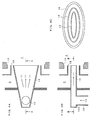
- FIG. 1 an ignition position (33) in a furnace (4) using a fuel-containing fluid supply nozzle (12) of a burner according to an embodiment shown in FIGS. 1A and 1B is compared with that in a conventional art shown in FIGS. 1C and 1D.
- FIG. 1A is a sectional view of the fuel-containing fluid supply nozzle (12) of the burner according to the present embodiment taken in an ejection flow direction of a fuel-containing fluid (11)
- FIG. 1B is a front view of an outlet part of the fuel-containing fluid supply nozzle (12) of FIG. 1A as viewed from the furnace (4) side
- FIG. 1C is a sectional view of the fuel-containing fluid supply nozzle (12) of the burner according to the conventional art taken in the ejection flow direction of the fuel-containing fluid
- FIG. 1D is a front view of the outlet part of the fuel-containing fluid supply nozzle (12) as viewed from the furnace (4) side.
- the ring-shaped ignition position (33) is present in a periphery of the ejection flow of circular cross section of the fuel-containing fluid (11) that is ejected from the fuel-containing fluid supply nozzle (12) of the burner.
- the ignition position (33) is present in a periphery of the ejection flow of rectangular cross section of the fuel-containing fluid (11) that is ejected from the fuel-containing fluid supply nozzle (12) of the burner as shown in FIG. 1B .
- a length L2 ( FIG. 1B ) from the ignition position (33) to a central part of the ejection flow of the fuel-containing fluid (11) inside the furnace (4) in a direction perpendicular to the ejection flow of rectangular cross section of the fuel-containing fluid (11) is reduced significantly in comparison with the length L2' ( FIG. 1D ) from the ignition position (33) to the central part of the ejection flow of the fuel-containing fluid (11) in the direction perpendicular to the ejection flow of circular cross section.
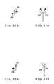
- FIG. 2 shows sectional views of the fuel-containing fluid supply nozzle (12) of the burner showing that a distance (unignited distance) L1 ( FIG. 2A ) that a flame propagates from the ignition position (33) to the central part of the fuel ejection flow in an ejection flow direction of the fuel-containing fluid (11) from the fuel-containing fluid supply nozzle (12) in the embodiment is reduced in comparison with the unignited distance L1' ( FIG. 2B ) in the conventional art.
- the unignited distance L1 is reduced significantly in comparison with the unignited distance L1' of the conventional art.
- FIG. 3 shows a structural example of a burner according to an embodiment of the present invention.
- FIG. 3A is a sectional view taken through a central axis of the burner in a direction parallel to a longest axis of a major axis part of an outlet part (sectional view taken on line B-B of FIG. 3B),
- FIG. 3B is a sectional view taken on line A-A of FIG. 3A, and
- FIG. 3C is a front view of the outlet part of the burner as viewed from the furnace (4) side.
- a cylindrical fuel-containing fluid flow passage (10) is connected via a connecting part (10a) of circular cross section to the fuel-containing fluid supply nozzle (12) having a rectangular cross section and has an adequate configuration for forming the ejection flow of rectangular cross section from the fuel-containing fluid supply nozzle (12) into the furnace (4). Even after the fuel-containing fluid (11) is loaded into the furnace (4), the fuel-containing fluid (11) spreads along the ejection flow directions and a cross-sectional area of the ejection flow of the fuel-containing fluid (11) expands while a flow velocity decreases, thereby effectively reducing the unignited distance L1 shown in FIG. 2 further.
- a combustion air sleeve (15) of rectangular cross section and a burner throat (16) of rectangular cross section are disposed in a periphery of the fuel-containing fluid supply nozzle (12).
- FIG. 4 shows a structural example of a burner according to an embodiment of the present invention.
- FIG. 4A is a sectional view taken through a central axis of the burner in a direction parallel to a longest axis of a major axis part of an outlet part (sectional view taken on line B-B of FIG. 4B),
- FIG. 4B is a sectional view taken on line A-A of FIG. 4A, and
- FIG. 4C is a front view of the outlet part of the burner as viewed from the furnace (4) side.
- the cross section of the burner in the direction perpendicular to the ejection flow of the fuel-containing fluid (11) has an elliptical shape, and configurations of other parts are the same as those of the burner shown in FIG. 3 .
- FIG. 5 shows a structural example of a burner according to an embodiment of the present invention.
- FIG. 5A is a sectional view taken through a central axis of the burner in a direction parallel to a longest axis of a major axis part of an outlet part (sectional view taken on line B-B of FIG. 5B),
- FIG. 5B is a sectional view taken on line A-A of FIG. 5A, and
- FIG. 5C is a front view of the outlet part of the burner as viewed from the furnace (4) side.
- a size of the major axis part gradually increases along the flow direction of the fuel-containing fluid (11) from the fuel-containing fluid connecting part (10a) of the fuel-containing fluid supply nozzle (12) toward the outlet part
- a size of a minor axis part gradually decreases along the direction of flow of the fuel-containing fluid (11)
- configurations of other parts are the same as those of the burner shown in FIG. 3 .
- a characteristic of the burner structure shown in FIG. 5 is that increase of the flow velocity of the fuel-containing fluid (11) from the fuel-containing fluid connecting part (10a) toward the outlet part of the fuel-containing fluid supply nozzle (12) can be suppressed to minimize pressure loss and suppress wear of component parts inside the fuel-containing fluid supply nozzle (12).
- FIG. 6 shows a structural example of a burner according to an embodiment of the present invention.
- FIG. 6A is a sectional view taken through a central axis of the burner in a direction parallel to a longest axis of a major axis part of an outlet part (sectional view taken on line B-B of FIG. 6B),
- FIG. 6B is a sectional view taken on line A-A of FIG. 6A, and
- FIG. 6C is a front view of the outlet part of the burner as viewed from the furnace (4) side.
- fuel-containing fluid guide plates (19) are disposed so that the fuel-containing fluid (11) flowing inside the fuel-containing fluid supply nozzle (12) is uniformly supplied in directions in which the fuel-containing fluid supply nozzle (12) expands along the ejection flow direction, and configurations of other parts are the same as those of the burner shown in FIG. 5 .
- a central guide plate (19) is disposed along the central axis and guide plates (19) at both sides that sandwich the central guide plate (19) are disposed at angles ⁇ and ⁇ with respect to a vertical section passing through the central axis.
- the fuel-containing fluid (11) flowing inside the fuel-containing fluid supply nozzle (12) is partitioned plurally by the fuel-containing fluid guide plates (19), the fuel-containing fluid (11) is spread uniformly according to the spreading of the fuel-containing fluid supply nozzle (12) from the fuel-containing fluid connecting part (10a) toward the outlet part of the fuel-containing fluid supply nozzle (12) and can be combusted without imbalance. Also, by the fuel-containing fluid (11) being spread uniformly, the effects of suppression of localized increase of flow velocity, minimization of pressure loss, and suppression of wear of component parts are improved over those of the configuration shown in FIG. 5 .
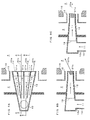
- FIG. 7 shows a structural example of a burner according to an embodiment of the present invention.
- FIG. 7A is a sectional view taken through a central axis of the burner in a direction parallel to a longest axis of a major axis part of an outlet part
- FIG. 7B is a sectional view taken on line B-B of FIG. 7A
- FIG. 7C is a sectional view taken on line A-A of FIG. 7A .
- the fuel-containing fluid guide plates (19) are disposed in the same manner as in the burner shown in FIG. 6 so that the fuel-containing fluid (11) flowing inside the fuel-containing fluid supply nozzle (12) is uniformly supplied in directions in which the fuel-containing fluid supply nozzle (12) expands along the flow direction, and in the section taken on line A-A of FIG.
- fuel-containing fluid direction changing guide plates (21a) that change the flow of the fluid (11) downward with respect to a plane along a line, passing through the central axis of the fuel-containing fluid supply nozzle (12) and extending toward the furnace (4), and parallel to the longest axis of the major axis part of the outlet part are installed at the burner outlet part, and in the section taken on line B-B of FIG. 7A , fuel-containing fluid direction changing guide plates (21b) that change the flow of the fluid (11) upward with respect to the abovementioned plane are installed at the burner outlet part.
- FIG. 8 shows a structural example of a burner according to an embodiment of the present invention.
- FIG. 8A is a sectional view taken through a central axis of the burner in a direction parallel to a longest axis of a major axis part of an outlet part
- FIG. 8B is a sectional view taken on line B-B of FIG. 8A
- FIG. 8C is a sectional view taken on line A-A of FIG. 8A .
- the fuel-containing fluid guide plates (19) are disposed in the same manner as in the burner shown in FIG. 7 so that the fuel-containing fluid (11) flowing inside the fuel-containing fluid supply nozzle (12) is uniformly supplied in directions in which the fuel-containing fluid supply nozzle (12) expands along the flow direction, and in the section taken on line A-A of FIG.
- fuel-containing fluid direction changing guide plates (21a) that rectify and make the flow of the fluid (11) rectilinear with respect to a plane along a line, passing through the central axis of the fuel-containing fluid supply nozzle (12) and extending toward the furnace (4), and parallel to the longest axis of the major axis part of the outlet part are installed at the burner outlet part, and in the section taken on line B-B of FIG. 8A , fuel-containing fluid direction changing guide plates (21b) that change the flow of the fluid (11) upward with respect to the abovementioned plane are installed at the burner outlet part.
- fuel-containing fluid ejection flows 20 (20a, 20b) formed by the fuel-containing fluid supply nozzle (12) and the fuel-containing fluid guide plates (19), are formed to fuel-containing fluid ejection flows (20a) in a rectilinear direction and fuel-containing fluid ejection flows (20b) that are upwardly directed ejection flows by installation of the above-mentioned fuel-containing fluid direction changing guide plates (21a, 21b).
- the dispersion of the fuel-containing fluid ejection flow (20) inside the furnace (4) is promoted to maintain the effect of promoting the combustion at the wake part of the furnace (4) and provide an effect of suppressing inflow of a flame to a vicinity of the side wall of the furnace (4) to prevent ash deposition.
- FIG. 9 shows a structural example of a burner according to an embodiment of the present invention.
- FIG. 9A is a sectional view taken through a central axis of the burner in a direction parallel to a longest axis of a major axis part of an outlet part
- FIG. 9B is perspective view of the burner
- FIG. 9C is a sectional view taken on line B-B of FIG. 9A
- FIG. 9D is a sectional view taken on line A-A of FIG. 9A .
- the fuel-containing fluid guide plates (19) are disposed in the same manner as in the burner shown in FIG. 7 so that the fuel-containing fluid (11) flowing inside the fuel-containing fluid supply nozzle (12) is uniformly supplied in directions in which the fuel-containing fluid supply nozzle (12) expands along the flow direction.
- a front side of an inlet part of the fuel-containing fluid supply nozzle (12) has a parallelepiped shape, one side surface (12a) of the fuel-containing fluid supply nozzle (12) leads to the outlet of the fuel-containing fluid supply nozzle (12) while being disposed obliquely downward along the flow direction and the other side surface (12b) leads to the outlet while being disposed obliquely upward along the flow direction.
- an obliquely downwardly directed fuel-containing fluid ejection flow (20a) is formed at a portion close to the side surface (12a) of the fuel-containing fluid supply nozzle (12) as shown in FIG. 9D
- an obliquely upwardly directed fuel-containing fluid ejection flow (20d) is formed at a portion close to the side surface (12b) of the fuel-containing fluid supply nozzle (12) as shown in FIG. 9C .
- a fuel-containing fluid ejection flow (20b) having an ejection flow direction intermediate the fuel-containing fluid ejection flow (20a) and the central line and a fuel-containing fluid ejection flow (20c) having an ejection flow direction intermediate the fuel-containing fluid ejection flow (20d) and the central line are formed.
- FIG. 10 shows a structural example of a burner according to an embodiment of the present invention.
- FIG. 10A is a sectional view taken through a central axis of the burner in a direction parallel to a longest axis of a major axis part of an outlet part (sectional view taken on line B-B of FIG. 10B),
- FIG. 10B is a sectional view taken on line A-A of FIG. 10A, and
- FIG. 10C is a front view of the outlet part of the burner as viewed from the furnace (4) side.
- the fuel-containing fluid ejection flow (20) is partitioned into four by the fuel-containing fluid partitioning plates (22) as shown in FIG. 11 .
- the fuel-containing fluid ejection flow (20) increases in surface area, the radiant heating inside the furnace (4) increases, negative pressure regions (22a) are formed at the wake side of the fuel-containing fluid partitioning plates (22), and high-temperature gas in the periphery flows into the negative pressure regions (22a) as indicated by arrows in the figure.
- FIG. 12 shows a structural example of a burner according to an embodiment of the present invention.
- FIG. 12A is a sectional view taken through a central axis of the burner in a direction parallel to a longest axis of a major axis part of an outlet part (sectional view taken on line B-B of FIG. 12B),
- FIG. 12B is a sectional view taken on line A-A of FIG. 12A, and
- FIG. 12C is a front view of the outlet part of the burner as viewed from the furnace (4) side.
- the fuel-containing fluid partitioning plates (22), perpendicular to the flow of the fuel-containing fluid (11) and partially blocking the flow, are disposed at the outlet parts of the fuel-containing fluid guide plates (19) at the outlet part of the fuel-containing fluid supply nozzle (12). Because the fuel-containing fluid (11) is supplied uniformly inside the fuel-containing fluid supply nozzle (12) by the fuel-containing fluid guide plates (19), the reduction of NOx and improvement in the combustion efficiency are realized more effectively.
- FIG. 13 shows a structural example of a burner according to an embodiment of the present invention.
- FIG. 13A is a sectional view taken through a central axis of the burner in a direction parallel to a longest axis of a major axis part of an outlet part (sectional view taken on line B-B of FIG. 13B),
- FIG. 13B is a sectional view taken on line A-A of FIG. 13A, and
- FIG. 13C is a front view of the outlet part of the burner as viewed from the furnace (4) side.
- a flame stabilizer (17) with an L-shaped cross section is installed at the outlet part of the fuel-containing fluid supply nozzle (12). Because a circular vortex (not shown) is formed at a wake of the flame stabilizer (17) and draws back the high-temperature combustion gas to the vicinity of the flame stabilizer (17), the configuration contributes to early ignition of the fuel and promotes combustion in the reducing region in the vicinity of the burner to effectively contribute to reduction of the NOx concentration in the combustion gas and improvement in the combustion efficiency.
- FIG. 14 shows a structural example of a burner according to an embodiment of the present invention.
- FIG. 14A is a sectional view taken through a central axis of the burner in a direction parallel to a longest axis of a major axis part of an outlet part (sectional view taken on line B-B of FIG. 14B),
- FIG. 14B is a sectional view taken on line A-A of FIG. 14A, and
- FIG. 14C is a front view of the outlet part of the burner as viewed from the furnace (4) side.
- a secondary air guide plate (17a) that outwardly spreads ejection directions of a secondary air is installed at a front end of the flame stabilizer (17) of L-shaped cross section shown in FIG. 14 .
- the vortex flow (not shown) at the wake of the flame stabilizer (17) is enlarged, a recirculation amount of the high-temperature gas is increased, ignition of the fuel is quickened further, and combustion in the reducing region in the vicinity of the burner is promoted to effectively contribute to reduction of the NOx concentration in the combustion gas and improvement in the combustion efficiency.
- FIG. 15 shows a structural example of a burner according to an embodiment of the present invention.
- FIG. 15A is a sectional view taken through a central axis of the burner in a direction parallel to a longest axis of a major axis part of an outlet part (sectional view taken on line B-B of FIG. 15B),
- FIG. 15B is a sectional view taken on line A-A of FIG. 15A, and
- FIG. 15C is a front view of the outlet part of the burner as viewed from the furnace (4) side.
- a tertiary air guide plate (15a) that outwardly spreads ejection directions of a tertiary air is installed at a front end of a secondary air sleeve (15) .
- a reducing region at a center part of the flame is enlarged to effectively contribute to reduction of the NOx concentration in the combustion gas and improvement in the combustion efficiency.
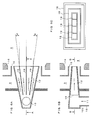
- FIG. 16 shows a structural example of a burner according to an embodiment of the present invention.
- FIG. 16A is a sectional view taken through a central axis of the burner in a direction parallel to a longest axis of a major axis part of an outlet part (sectional view taken on line B-B of FIG. 16B),
- FIG. 16B is a sectional view taken on line A-A of FIG. 16A, and
- FIG. 16C is a front view of the outlet part of the burner as viewed from the furnace (4) side.
- a fuel-containing fluid condenser (23) combining a triangular prism gradually increasing in cross-sectional area from an upstream side and an oppositely directed triangular prism gradually decreasing in cross-sectional area at a downstream side, is installed inside the fuel-containing fluid supply nozzle (12).
- the fuel in the vicinity of the flame stabilizer (17) is condensed by the fuel-containing fluid condenser (23) and this contributes to early ignition of the fuel, promotes combustion in the reducing region near the burner, and thereby effectively contributes to reduction of the NOx concentration in the combustion gas and improvement in the combustion efficiency.
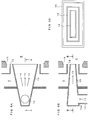
- FIG. 17 shows a structural example of a burner according to an embodiment of the present invention.
- FIG. 17A is a sectional view taken through a central axis of the burner in a direction parallel to a longest axis of a major axis part of an outlet part (sectional view taken on line B-B of FIG. 17B),
- FIG. 17B is a sectional view taken on line A-A of FIG. 17A, and
- FIG. 17C is a front view of the outlet part of the burner as viewed from the furnace (4) side.
- a fuel-containing fluid condenser (23') combining a triangular prism gradually increasing in cross-sectional area at an upstream side, a quadrangular prism at an intermediate part, and an oppositely directed triangular prism gradually decreasing in cross-sectional area at a downstream side, is installed inside the fuel-containing fluid supply nozzle (12) .
- delamination is suppressed by making an angular variation around the condenser (23') small and a fuel condensing effect is thereby promoted to heighten the NOx reducing effect and improve the combustion efficiency.
- FIG. 18 shows a structural example of a burner according to an embodiment of the present invention.
- FIG. 18A is a sectional view parallel to a fuel-containing fluid supply nozzle (12) surface formed through a long edge of an outlet part of the nozzle (12) (sectional view taken on line B-B of FIG. 18B),
- FIG. 18B is a sectional view taken on line A-A of FIG. 18A, and
- FIG. 18C is a front view of the outlet part of the burner as viewed from the furnace (4) side.
- a dam-like fluid distribution plate (24) is disposed at an inlet part of the fuel-containing fluid supply nozzle (12).
- the fuel-containing fluid (11) collides once with an upstream side of the dam-like fluid distribution plate (24) and, after being dispersed uniformly in the direction of a long edge of the fuel-containing fluid supply nozzle (12), is guided uniformly into the four flow passages partitioned by the fuel-containing fluid guide plates (19) inside the fuel-containing fluid supply nozzle (12) and supplied into the furnace (4) while being maintained in a uniform state.
- FIG. 19 shows an example where an oil supply nozzle (41) is installed at a central part of the fuel-containing fluid supply nozzle (12).
- FIG. 19A is a sectional view taken through a central axis of the burner in a direction parallel to a longest axis of a major axis part of an outlet part (sectional view taken on line B-B of FIG. 19B),
- FIG. 19B is a sectional view taken on line A-A of FIG. 19A, and
- FIG. 19C is a front view of the outlet part of the burner as viewed from the furnace (4) side.
- FIG. 20 shows an example where a gas ejection part, connected from a gas introduction tube (42) to gas supply nozzles (44) via a horizontal tube (43), is installed in a periphery of the flame stabilizer (17).
- FIG. 20A is a sectional view taken through a central axis of the burner in a direction parallel to a longest axis of a major axis part of an outlet part (sectional view taken on line B-B of FIG. 20B), FIG. 20B is a sectional view taken on line A-A of FIG. 20A, and FIG. 20C is a front view of the outlet part of the burner as viewed from the furnace (4) side.
- FIG. 21 shows, for a burner structure, a front view as viewed from the furnace (4) side ( FIG. 21A ) and a plan view ( FIG. 21B ) of the fuel-containing fluid supply nozzle (12), with which the cross-sectional shape perpendicular to the flow of the fuel-containing fluid (11) flowing inside the fuel-containing fluid supply nozzle (12) of the burner is rectangular, in a case where the fuel-containing fluid supply nozzle (12) is positioned with its long edge side directed in an up/down direction.
- the fuel-containing fluid ejection flows (20a, 20b) from the fuel-containing fluid supply nozzle (12) shown in FIG. 21 are formed obliquely toward mutually opposite sides in the horizontal direction to the left and right with respect to a plane perpendicular to the furnace wall surface in upper and lower directions of the long edge side of the nozzle (12).
- the forming of the present fuel-containing fluid ejection flows is achieved by applying the burner structure of FIG. 7 or FIG. 9 .
- FIG. 22 shows, for a burner structure, a front view as viewed from the furnace (4) side ( FIG. 22A ) and a plan view ( FIG. 22B ) of the fuel-containing fluid supply nozzle (12), with which the cross-sectional shape perpendicular to the flow of the fuel-containing fluid (11) flowing inside the fuel-containing fluid supply nozzle (12) of the burner is rectangular, in a case where the fuel-containing fluid supply nozzle (12) is positioned with its long edge side directed in an up/down direction.
- one fuel-containing fluid ejection flow (20b) from the fuel-containing fluid supply nozzle (12) shown in FIG. 22 is formed obliquely to the horizontal direction with respect to a plane perpendicular to the furnace wall surface in upper and lower directions of the long edge side of the nozzle (12) and the other fuel-containing fluid ejection flow (20c) is formed perpendicular to the furnace wall surface.
- the forming of the present fuel-containing fluid ejection flows is achieved by applying the burner structure of FIG. 8 .
- FIG. 23 shows an example where a plurality of the fuel-containing fluid supply nozzles (12), shown in FIG. 21 , are positioned in three stages in the up/down direction and four columns in the horizontal direction on a single furnace wall surface.
- Fuel-containing fluid supply nozzles (12) forming ejection flows (20a, 20b) in the same directions as the nozzles (12) shown in FIG. 21 are disposed at a right half of the single furnace wall, and fuel-containing fluid supply nozzles (12) forming ejection flows (20a, 20b) at mirror symmetric positions with respect to the fuel-containing fluid supply nozzles (12) shown in FIG. 21 are disposed at a left half of the furnace wall.
- the directions of the fuel-containing fluid ejection flows (20a, 20b) to be left/right symmetrical on the single furnace wall surface, a good left/right balance of flow and combustion states can be maintained in the furnace (4).
- FIG. 24 shows an example where a plurality of the fuel-containing fluid supply nozzles (12) are positioned in three stages in the up/down direction and four columns in the horizontal direction on a single furnace wall surface, with the fuel-containing fluid supply nozzles (12) shown in FIG. 22 being disposed mirror symmetrically at respective end columns at the left and right sides and the fuel-containing fluid supply nozzles (12) shown in FIG. 21 being disposed mirror symmetrically at two central columns.
- the dispersion within the furnace (4) is promoted to maintain the effect of promoting the combustion at the wake part of the furnace (4) while providing the effect of suppressing inflow of the flame to the vicinity of the side wall of the furnace (4) to prevent ash deposition.
- FIG. 25 shows an example where the fuel-containing fluid supply nozzles (12) that are all the same and form the fuel-containing fluid ejection flows (20a, 20b) shown in FIG. 21 are disposed as the fuel-containing fluid supply nozzles (12) of all of the burners on the single furnace wall.
- the present embodiment provides a configuration with which collision of the fuel-containing fluid ejection flows (20a, 20b) can be avoided, especially in a furnace (4) of small capacity, and localized concentration of fuel is suppressed to effectively reduce the NOx concentration in the combustion gas and improve the combustion efficiency.
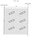
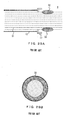
- FIG. 26 is a plan view of a furnace wall of a boiler in which burners according to an embodiment of the present invention are disposed.
- a boiler having spiral water wall tubes (25) on the furnace wall rectangular openings (26) are installed and the various burners described as the embodiments of the present invention are mounted along an arrangement of the water wall tubes (25) that is oblique with respect to the horizontal direction.
- a combustion equipment configured from the respective embodiments of the present invention has a characteristic of enabling the combustion space to be utilized effectively because the fuel-containing fluid ejection flows (20) spread inside the furnace (4), and with the configuration shown in FIG. 26 , because the fuel-containing fluid ejection flows (20a, 20b) spread in the horizontal (width) direction of the furnace (4), a distribution of the fuel-containing fluid (11) in the horizontal (width) direction of the furnace (4) is made uniform and the practical furnace retention time is made even longer, thereby effectively contributing to the reduction of NOx concentration in the combustion gas and improvement in combustion efficiency.
- FIG. 27 is a plan view of a furnace wall of a boiler in which burners according to an embodiment of the present invention are disposed.
- a boiler having water wall tubes (25) extending in the vertical direction on the furnace wall rectangular openings (26) are installed and the various burners described as the embodiments of the present invention are mounted along the arrangement of the water wall tubes (25).
- the openings (26) By disposing the openings (26) along the water wall tubes (25), the number of the water wall tubes (25) necessary for forming the openings (26) can be minimized to improve economy.
- An oil or a gas is generally used as an auxiliary fuel in a burner, and even when supply nozzles for such fuels are installed at a part of the burners according to the embodiments of the present invention, the characteristics and effects of the burners according to the embodiments of the present invention are maintained.
- the present invention is high in future industrial applicability.
Abstract


Description
- The present invention relates to a burner and a combustion equipment and a boiler including the burner, and particularly relates to a burner capable of performing low nitrogen oxide (NOx) combustion at high efficiency.
-
FIG. 28 shows an example of a solid fuel (pulverized coal, biomass fuel, etc.) burner according to a conventional art.FIG. 28A is a side sectional view of the burner, andFIG. 28B is a front view of the burner as viewed from a furnace (4) side. The solid fuel burner includes a fuel-containing fluid supply nozzle (12), defining a fuel-containing fluid flow passage through which a fuel-containing fluid (11), containing a solid fuel and a conveying primary air, flows toward the furnace (4), and a combustion air sleeve (15) disposed at an outer periphery of the fuel-containing fluid supply nozzle (12), and air inside a windbox (3) is supplied as a secondary air (13) and a tertiary air (14) through a combustion air flow passage defined by the sleeve (15). A flame stabilizer (17) is disposed at a front end of the fuel-containing fluid supply nozzle (12), and ignition of the fuel from a vicinity of the burner is enabled by an effect of a circular vortex formed at a wake of the flame stabilizer (17). - A front end of the combustion air sleeve (15) is disposed at a position facing a burner throat (16), a combustion air guide plate (15a), spreading outside the burner, is disposed at the front end of the sleeve (15), the tertiary air (14) is spread outward by the combustion air guide plate (15a) to delay mixing of air into a central part of a flame, and by promotion of combustion under a reducing atmosphere condition of insufficient air, generation of nitrogen oxides (NOx) in a combustion gas is suppressed.
-
FIG. 1C is a sectional view taken in a direction along an ejection flow of the fuel-containing fluid (11) at the fuel-containing fluid supply nozzle (12) in the burner of the conventional art, and as shown inFIG. 1D , which is a front view of an outlet part of the fuel-containing fluid supply nozzle (12) of the burner inFIG. 1C as viewed from the furnace (4) side, with the burner of the conventional art, a cross section of the outlet part of the fuel-containing fluid supply nozzle (12) has a shape close to a circular shape. When the fuel-containing fluid (11) is loaded into the furnace (4), the fuel is ignited near the outlet of the fuel-containing fluid supply nozzle (12) by heating due to radiation inside the furnace (4) and actions of the circular vortex at the wake of the flame stabilizer (17). -
FIG. 29A is a sectional view taken in a direction along the ejection flow of the fuel-containing fluid (11) at the fuel-containing fluid supply nozzle (12) in the burner of the conventional art, and an ignition position (33) of the fuel in the fuel-containing fluid ejected from the fuel-containing fluid supply nozzle (12) into the furnace (4) is formed as shown inFIG. 29B , which is a front view of the outlet part of the fuel-containing fluid supply nozzle (12) as viewed from the furnace (4) side. After the fuel is ignited at a surface of the ejection flow of the fuel containing fluid (11), a flame that is formed gradually propagates toward a central part of the ejection flow of the fuel-containing fluid (11).FIG. 30 schematically shows a propagation behavior of the flame inside the furnace (4) in a cross-sectional direction along the ejection flow of the fuel-containing fluid (11) at the fuel-containing fluid supply nozzle (12) in the burner of the conventional art. An ignited region (32) is formed around an unignited region (31) of conical shape. - The burner of circular cross section, shown in
FIGS. 28 to 30 , is frequently used in a so-called opposed firing configuration in which the burners is disposed at each of a pair of opposing furnace walls. Meanwhile, in so-called tangential firing in which the fuel is combusted while the fuel-containing fluid is ejected into the furnace (4) in directions of applying a rotation along a furnace wall surface from outlets of a plurality of fuel-containing fluid supply nozzles (12), an outlet shape of a transverse section (section orthogonal to the flow of the fuel-containing fluid) of each fuel-containing fluid supply nozzle (12) is made a square shape or a rectangular shape close to a square shape in many cases. - Burners, with which the outlet shape of the transverse section (section orthogonal to the flow of the fuel-containing fluid) of the fuel-containing fluid supply nozzle (12) is made a rectangular shape, an elliptical shape, or a substantially elliptical shape with major and minor axis parts, are disclosed in the following
Patent Documents 1 to 3. - Patent Document 1: Japanese Translation of International Application (Kohyo) No.
Sho 59-500981 - Patent Document 2: Japanese Published Patent Application No.
Hei 8-226615 - Patent Document 3: Japanese Published Patent Application No.
Hei 11-281009 - In general, a cross section of an outlet part of a fuel-containing fluid supply nozzle (12) of a burner has a shape close to a circular shape or a square shape, and there are cases where, as shown in
FIG. 30 , a flame ignited at an outer side of a fuel-containing fluid ejection flow in a furnace (4) must propagate a considerable distance to reach a central part of the fuel-containing fluid ejection flow. A distance in a fuel-containing fluid (11) ejection flow direction from the fuel-containing fluid supply nozzle (12) that is required for the ignited flame to propagate to the central part of the fuel ejection flow, in other words, an unignited distance L1' shown inFIG. 30 is longer and an unignited region (31) is more expanded the larger a diameter or a peripheral part of the fuel-containing fluid supply nozzle (12). Although promotion of combustion in a reducing region in a vicinity of the burner is important for suppressing NOx generation in a combustion gas, expansion of the unignited region (31) inhibits the NOx concentration suppression characteristic. Expansion of the unignited region (31) also means that a combustion time after ignition is short and causes lowering of combustion efficiency. - Although increasing a burner capacity (decreasing a number of burners) is an effective method for reducing cost and improving operability, with the conventional art, when the burner capacity is increased, a diameter or a length of an outer diameter part of the fuel-containing fluid supply nozzle (12) becomes long and the unignited region (31) expands, causing increase of NOx and lowering of the combustion efficiency. This problem was due to the distance from an ignited region (32) at a fuel-containing fluid ejection flow surface to the central part of the fuel-containing fluid ejection flow being large. Also, with the inventions described in
Patent Documents 1 to 3 where the outlet shape of the transverse section (section orthogonal to the flow of the fuel-containing fluid) of the fuel-containing fluid supply nozzle (12) is made a rectangular shape, etc. that combines major and minor axis parts, nothing is mentioned in regard to a countermeasure for the expansion of the unignited region (31) due to increase of the burner capacity and the resulting increase of NOx and lowering of the combustion efficiency. - An object of the present invention is to provide a solid fuel burner that is increased in capacity over the conventional art and yet is suppressed in expansion of an unignited region to prevent increase of NOx concentration in a combustion gas and prevent lowering of combustion efficiency, a combustion equipment and a boiler including the burner.
- The above object of the present invention is achieved by the following solutions.
- A first aspect of the present invention provides a burner including: a fuel-containing fluid supply nozzle (12) supplying a fuel-containing fluid (11), containing a solid fuel and a medium for transfer of the solid fuel, to an outlet part disposed on a wall surface of a furnace (4) from a connecting part (10a) of a fuel-containing fluid transfer flow passage (10) that transfers the fluid (11); and one or more air supply nozzles (15) supplying combustion air and disposed at an outer peripheral part of the fuel-containing fluid supply nozzle (12); and where, from the connecting part (10a) of the fluid transfer flow passage (10) toward the outlet part disposed on the wall surface of the furnace (4), a cross section of the fuel-containing fluid supply nozzle (12) perpendicular to a flow of the fluid (11) has a rectangular, elliptical, or substantially elliptical shape with major and minor axis parts and, from the connecting part (10a) of the fluid transfer flow passage (10) toward the outlet part, a size of the major axis part of the cross section perpendicular to the flow of the fluid (11) increases gradually along a direction of the flow of the fluid (11).
- A second aspect of the present invention provides the burner according to the first aspect where the fuel-containing fluid supply nozzle (12) has a configuration such that, from the connecting part (10a) of the fluid transfer flow passage (10) toward the outlet part, the size of the major axis part of the cross section perpendicular to the flow of the fluid (11) increases gradually along the direction of the flow of the fluid (11) and a size of the minor axis part is unchanged.
- A third aspect of the present invention provides the burner according to the first aspect where the fuel-containing fluid supply nozzle (12) has a configuration such that, from the connecting part (10a) of the fluid transfer flow passage (10) toward the outlet part, the size of the major axis part of the cross section perpendicular to the flow of the fluid (11) increases gradually along the direction of the flow of the fluid (11) and a size of the minor axis part decreases gradually along the direction of the flow of the fluid (11).
- A fourth aspect of the present invention provides the burner according to any of the first to third aspects where the fuel-containing fluid supply nozzle (12) has, in an interior thereof, fuel-containing fluid guide plates (19) plurally partitioning the flow of the fuel-containing fluid (11).
- A fifth aspect of the present invention provides the burner according to the fourth aspect where the fuel-containing fluid guide plates (19) are disposed at a plurality of different inclination angles with respect to a plane passing along a line extending a central axis in the direction of the flow of the fluid (11) in the fuel-containing fluid supply nozzle (12) toward the furnace (4) and parallel to a shortest axis of the minor axis part of the nozzle (12).
- A sixth aspect of the present invention provides the burner according to any of the first to fifth aspects where the fuel-containing fluid supply nozzle (12) has, in an interior of the outlet thereof, fuel-containing fluid direction changing guide plates (21) forcibly changing a direction of ejection flow of the fuel-containing fluid (11).
- A seventh aspect of the present invention provides the burner according to the sixth aspect where the fuel-containing fluid direction changing guide plates (21) are disposed in a plurality of mutually different directions with respect to a plane passing along the line extending the central axis of the fuel-containing fluid supply nozzle (12) toward the furnace (4) and parallel to a longest axis of the major axis part of the nozzle (12).
- An eighth aspect of the present invention provides the burner according to the sixth aspect where the fuel-containing fluid direction changing guide plates (21) for a portion of the fuel-containing fluid (11) are disposed parallel to the plane passing along the line extending the central axis of the fuel-containing fluid supply nozzle (12) toward the furnace (4) and parallel to the longest axis of the major axis part of the nozzle (12), and the fuel-containing fluid direction changing guide plates (21) for another portion of the fuel containing fluid (11) are disposed at an inclination angle with respect to the plane passing along the line extending the central axis of the fuel-containing fluid supply nozzle (12) toward the furnace (4) and parallel to the longest axis of the major axis part of the nozzle (12).
- A ninth aspect of the present invention provides the burner according to the fourth aspect where the fuel-containing fluid supply nozzle (12) is partitioned into a plurality of flow passages by the fuel-containing fluid guide plates (19), and central axes of the respective flow passages are disposed at the wall surface of the furnace (4) at a plurality of mutually different inclination angles with respect to the plane passing along the line extending the central axis of the fuel-containing fluid supply nozzle (12) toward the furnace (4) and parallel to the longest axis of the major axis part of the nozzle (12) outlet.
- A tenth aspect of the present invention provides the burner according to any of the first to ninth aspects where fuel-containing fluid partitioning plates (22), capable of plurally partitioning the outlet part of the fuel-containing fluid supply nozzle (12), are disposed at the outlet part.
- An eleventh aspect of the present invention provides the burner according to any of the first to tenth aspects where a flame stabilizer (17) with an L-shaped cross section is disposed at the outlet part of the fuel-containing fluid supply nozzle (12).
- A twelfth aspect of the present invention provides the burner according to the eleventh aspect where a guide plate (17a) outwardly changing an ejection direction of the combustion air in a periphery of the flame stabilizer (17) is disposed at a front end of the L-shaped flame stabilizer (17).
- A thirteenth aspect of the present invention provides the burner according to any of the first to twelfth aspects where a combustion air guide plate (15a), outwardly spreading the ejection direction of the combustion air at an outer side of the one or more combustion air supply nozzles (15) disposed at the outer peripheral part of the nozzle (12) with respect to a fuel ejection direction, is disposed at a front end of the fuel-containing fluid supply nozzle (12).
- A fourteenth aspect of the present invention provides the burner according to any one of the first to thirteenth aspects where a condenser (23), narrowing the flow passage of the fuel-containing fluid (11) once and then expanding the flow passage again, is disposed in an interior of the fuel-containing fluid supply nozzle (12).
- A fifteenth aspect of the present invention provides the burner according to any one of the first to fourteenth aspects where a fluid distribution plate (24) distributing the fuel uniformly inside the fuel-containing fluid supply nozzle (12) is disposed at an inlet part of the fuel-containing fluid supply nozzle (12).
- A sixteenth aspect of the present invention provides the burner according to any of the first to fifteenth aspects where a nozzle (41, 44), ejecting a liquid fuel or a gas fuel that is an auxiliary fuel to a vicinity of the fluid (11) ejected from the fuel-containing fluid supply nozzle (12), is disposed at the vicinity of the fuel-containing fluid supply nozzle (12).
- A seventeenth aspect of the present invention provides a combustion equipment where the burners according to any of the first to sixteenth aspects are disposed in a plurality of stages in an up/down direction at each of two opposing furnace walls, and a plurality of burners disposed at each stage are disposed respectively symmetrically in wall surface regions divided in two at a central part of width in a horizontal direction of the same furnace wall.
- An eighteenth aspect of the present invention provides a combustion equipment where the burners according to any of the first to sixteenth aspects are disposed in the plurality of stages in the up/down direction at each of the two opposing furnace walls, and burners, which, among the plurality of burners disposed in each stage of the same furnace wall, are adjacent each other in the horizontal direction, are burners of the same structure.
- A nineteenth aspect of the present invention provides a boiler including: a furnace wall formed by spirally winding a set of water wall tubes (25) inclined with respect to a horizontal direction; and where openings (26) of rectangular, elliptical, or substantially elliptical shape are disposed in the furnace wall along a longitudinal direction of the water wall tubes (25) and the burner according to any of the first to sixteenth aspects is mounted in each opening (26).
- A twentieth aspect of the present invention provides a boiler including: a furnace wall formed by a set of water wall tubes (25) extending in a vertical direction; and where openings (26) of rectangular, elliptical, or substantially elliptical shape are disposed in the furnace wall along a longitudinal direction of the water wall tubes (25) and the burner according to any of the first to sixteenth aspects is mounted in each opening (26).
- According to the first aspect of the present invention, expansion of an unignited region can be suppressed even if a burner capacity is increased, an unignited distance can be reduced effectively in comparison with the conventional art because the fuel-containing fluid (11) spreads in the width direction even after the fuel-containing fluid (11) is loaded into the furnace (4) so that a cross-sectional area of the ejection flow of the fuel-containing fluid (11) increases and a flow velocity decreases, and also because the fuel-containing fluid (11) spreads inside the furnace (4), a combustion space can be utilized effectively and a practical furnace retention time is made long, thereby providing effects of reducing NOx concentration in a combustion gas and improving combustion efficiency.
- According to the second aspect of the present invention, the size of the minor axis part is unchanged and this is effective for simplification of structure. Also, the flow velocity at an upstream side of the fuel-containing fluid supply nozzle (12) can be made high and this is effective for preventing backfiring in a case of a readily ignitable fuel, etc.
- According to the third aspect of the present invention, the increase of the flow velocity of the fuel-containing fluid (11) from the fuel-containing fluid connecting part (10a) toward the outlet part of the fuel-containing fluid supply nozzle (12) can be suppressed to minimize pressure loss and suppress wear of component parts inside the fuel-containing fluid supply nozzle (12).
- According to the fourth and fifth aspects of the present invention, because the flow of the fuel-containing fluid (11) is partitioned plurally by the fuel-containing fluid guide plates (19) in the interior of the fuel-containing fluid supply nozzle (12), the fuel-containing fluid (11) is supplied uniformly in the direction in which the fuel-containing fluid supply nozzle (12) expands from the fuel-containing fluid connecting part (10a) toward the outlet part of the nozzle (12), and the effects of NOx reduction, improvement in combustion efficiency, suppression of flow velocity increase, minimization of pressure loss, and suppression of wear of component parts are improved in comparison with other those of the third aspect of the present invention.
- According to the sixth aspect of the present invention, effects of promoting dispersion of the fuel-containing fluid ejection flow (20) inside the furnace (4) and promoting combustion at a wake part of the furnace (4) are provided.
- According to the seventh aspect of the present invention, because the fuel-containing fluid guide plates (19) are respectively disposed in mutually opposing directions with respect to the plane passing along the line extending the central axis of the fuel-containing fluid supply nozzle (12) toward the furnace (4) and parallel to the longest axis of the major axis part of the nozzle (12), the fuel-containing fluid (11) can be ejected into the furnace (4) in two or more groups and the fuel-containing fluid ejection flow (20) can thereby be divided into groups by a simple structure to provide the effects of promoting the dispersion of the fuel-containing fluid ejection flow (20) inside the furnace (4) and promoting the combustion at the wake part of the furnace (4).
- According to the eighth aspect of the present invention, by dividing four fuel-containing fluid ejection flows (20), formed by the fuel-containing fluid supply nozzle (12) and the fuel-containing fluid guide plates (19) into two groups (20a, 20b) and thereby making, for example, fuel-containing fluid ejection flows (20a), adjacent a furnace side wall, rectilinear flows and making fuel-containing fluid ejection flows (20b), not adjacent the furnace side wall, be ejected upon applying an inclination with respect to a horizontal direction, an effect of preventing ash deposition by suppressing flame inflow to a vicinity of the furnace side wall while maintaining promotion of combustion at the furnace wake part by dispersion of the fuel is provided.
- According to the ninth aspect of the present invention, because the fuel-containing fluid (11) can be ejected into the furnace (4) at mutually different angles with respect to the horizontal direction or the vertical direction from the fuel-containing fluid supply nozzle (12) and the fuel-containing fluid ejection flow (20) can be varied in direction without using parts inside the fuel-containing fluid supply nozzle (12) with which pulverized coal or other solid fuel collides directly, wear of parts can be suppressed effectively.
- According to the tenth aspect of the present invention, the fuel-containing fluid ejection flow (20) is partitioned by the fuel-containing fluid partitioning plates (22) to be increased in surface area, and radiant heat inside the furnace (4) is thereby increased and a negative pressure region is formed at the wake side of the fluid partitioning plates (22), thereby making a high temperature gas in a periphery flow into the negative pressure region to contribute to early ignition of the fuel, promote combustion at a reducing region in the vicinity of the burner, and effectively contribute to the reduction of the NOx concentration in the combustion gas and the improvement in the combustion efficiency.
- According to the eleventh aspect of the present invention, by disposing the flame stabilizer (17) with the L-shaped cross section at the outlet part of the fuel-containing fluid supply nozzle (12), a circular vortex is formed at the wake of the flame stabilizer (17) and draws back the high-temperature combustion gas to a vicinity of the flame stabilizer (17) to contribute to early ignition of the fuel, promote combustion at the reducing region in the vicinity of the burner, and effectively contribute to the reduction of the NOx concentration in the combustion gas and the improvement in the combustion efficiency in compassion with the eleventh aspect of the invention.
- According to the twelfth aspect of the present invention, by the secondary air guide plate (17a) at the front end of the flame stabilizer (17) of L-shaped cross section, the secondary air is spread outward and the circular vortex at the wake of the flame stabilizer (17) is enlarged, thereby increasing a recirculation amount of the high-temperature combustion gas to further quicken ignition of the fuel, promote combustion at the reducing region near the burner, and effectively contribute to the reduction of the NOx concentration in the combustion gas and the improvement in the combustion efficiency in comparison with the eleventh aspect of the invention.
- According to the thirteenth aspect of the present invention, by provision of the combustion air guide plate (15a) that spreads the combustion air ejection direction at the outer side of the combustion air supply nozzles (15) outward with respect to the fuel-containing fluid ejection direction, the combustion air is spread outward, thereby enlarging the reducing region at a central part of the flame and effectively contributing to the reduction of the NOx concentration in the combustion gas and the improvement in the combustion efficiency.
- According to the fourteenth aspect of the present invention, the fuel in the vicinity of the flame stabilizer (17) is condensed by the condenser (23) thereby contributing to early ignition of the fuel to promote combustion at a reducing region in the vicinity of the burner and effectively contributing to the reduction of the NOx concentration in the combustion gas and the improvement in the combustion efficiency.
- According to the fifteenth aspect of the present invention, the fuel concentration at the inlet part of the fuel-containing fluid supply nozzle (12) is made uniform by the fluid distribution plate (24) to suppress imbalance of concentration of the fuel flowing into the respective flow passages partitioned by the fuel-containing fluid guide plates (19), and this is effective for NOx reduction and improvement in the combustion efficiency.
- According to the sixteenth aspect of the present invention, because the liquid fuel or the gas fuel is ejected to the burner outlet, the fuel-containing fluid (11) that contains the solid fuel can be ignited reliably.
- According to the seventeenth aspect of the present invention, by the burners according to any of the first to sixteenth aspects being disposed in the plurality of stages in the up/down direction at each of the opposing furnace walls of the opposed firing type furnace (4) and by disposing the plurality of burners of each stage respectively symmetrically at the wall surface regions divided in two at the central part of width in the horizontal direction of the same furnace wall, the directions of the fluid ejection flows (20a, 20b) can be made left/right symmetrical at a single furnace wall surface and good left/right balance of flow and combustion states can be maintained in the furnace (4).
- According to the eighteenth aspect of the present invention, by the burners according to any of the first to sixteenth aspects being disposed in the plurality of stages in the up/down direction at each of the two opposing furnace walls of the opposed firing type furnace (4) and by making the burners, which, among the plurality of burners disposed in each stage of the same furnace wall, are adjacent each other in the horizontal direction, burners of the same structure, collision of the fuel-containing fluid ejection flows (20a, 20b) can be avoided, especially in a furnace (4) of small capacity, to suppress localized concentration of fuel and provide the effects of reducing the NOx concentration in the combustion gas and improving the combustion efficiency.
- According to the nineteenth aspect of the present invention, by aligning a longitudinal direction of the water wall tubes (25) with a longitudinal direction of the major axis parts of the openings (26), a number of the spiral water wall tubes (25) necessary for forming the openings (26) can be made small and an economical boiler can be constructed with few processed and bent parts in the water wall tubes (25). The number of the spiral water wall tubes (25) necessary for forming the openings (26) can be minimized to improve economy. Also, because the fuel-containing fluid (11) spreads in the horizontal (width) direction of the furnace (4), distribution of the fuel-containing fluid (11) in the horizontal (width) direction of the furnace (4) is made uniform, the practical furnace retention time is made longer, and the effects of reducing the NOx concentration in the combustion gas and improving the combustion efficiency are provided.
- According to the twentieth aspect of the present invention, because the rectangular openings (26) are installed on the furnace wall along the arrangement of the water wall tubes (25) in the vertical direction, by aligning the longitudinal direction of the water wall tubes (25) with the longitudinal direction of the major axis parts of the openings (26), an economical boiler can be constructed with few processed and bent parts in the water wall tubes (25).
-
-
FIG. 1 shows explanatory diagrams of ignited regions of burner outlets according to the present invention and a conventional art. -
FIG. 2 shows explanatory diagrams of unignited regions of the burner outlets according to the present invention and the conventional art. -
FIG. 3 shows a structural example of a burner according to an embodiment of the present invention (FIG. 3A is a sectional view taken through a central axis of the burner in a direction parallel to a longest axis of a major axis part of an outlet part,FIG. 3B is a sectional view taken on line A-A ofFIG. 3A, and FIG. 3C is a front view of the outlet part of the burner as viewed from the furnace side). -
FIG. 4 shows a structural example of a burner according to an embodiment of the present invention (FIG. 4A is a sectional view taken through a central axis of the burner in a direction parallel to a longest axis of a major axis part of an outlet part,FIG. 4B is a sectional view taken on line A-A ofFIG. 4A, and FIG. 4C is a front view of the outlet part of the burner as viewed from the furnace side). -
FIG. 5 shows a structural example of a burner according to an embodiment of the present invention (FIG. 5A is a sectional view taken through a central axis of the burner in a direction parallel to a longest axis of a major axis part of an outlet part,FIG. 5B is a sectional view taken on line A-A ofFIG. 5A, and FIG. 5C is a front view of the outlet part of the burner as viewed from the furnace side). -
FIG. 6 shows a structural example of a burner according to an embodiment of the present invention (FIG. 6A is a sectional view taken through a central axis of the burner in a direction parallel to a longest axis of a major axis part of an outlet part,FIG. 6B is a sectional view taken on line A-A ofFIG. 6A, and FIG. 6C is a front view of the outlet part of the burner as viewed from the furnace side). -
FIG. 7 shows a structural example of a burner according to an embodiment of the present invention (FIG. 7A is a sectional view taken through a central axis of the burner in a direction parallel to a longest axis of a major axis part of an outlet part,FIG. 7B is a sectional view taken on line B-B ofFIG. 7A, and FIG. 7C is a sectional view taken on line A-A ofFIG. 7A ). -
FIG. 8 shows a structural example of a burner according to an embodiment of the present invention (FIG. 8A is a sectional view taken through a central axis of the burner in a direction parallel to a longest axis of a major axis part of an outlet part,FIG. 8B is a sectional view taken on line B-B ofFIG. 8A, and FIG. 8C is a sectional view taken on line A-A ofFIG. 8A ). -
FIG. 9 shows a structural example of a burner according to an embodiment of the present invention (FIG. 9A is a sectional view taken through a central axis of the burner in a direction parallel to a longest axis of a major axis part of an outlet part,FIG. 9B is perspective view of the burner,FIG. 9C is a sectional view taken on line B-B ofFIG. 9A, and FIG. 9D is a sectional view taken on line A-A ofFIG. 9A ). -
FIG. 10 shows a structural example of a burner according to an embodiment of the present invention (FIG. 10A is a sectional view taken along a line, passing through a central axis of the burner and extending toward the furnace, in a direction parallel to a longest axis of a major axis part of an outlet part,FIG. 10B is a sectional view taken on line A-A ofFIG. 10A, and FIG. 10C is a front view of the outlet part of the burner as viewed from the furnace side). -
FIG. 11 is an explanatory diagram of effects of the invention shown inFIG. 10 . -
FIG. 12 shows a structural example of a burner according to an embodiment of the present invention shown inFIG. 10 (FIG. 12A is a sectional view taken along a line, passing through a central axis of the burner and extending toward the furnace, in a direction parallel to a longest axis of a major axis part of an outlet part,FIG. 12B is a sectional view taken on line A-A ofFIG. 12A, and FIG. 12C is a front view of the outlet part of the burner as viewed from the furnace side). -
FIG. 13 shows a structural example of a burner according to an embodiment of the present invention (FIG. 13A is a sectional view taken through a central axis of the burner in a direction parallel to a longest axis of a major axis part of an outlet part,FIG. 13B is a sectional view taken on line A-A ofFIG. 13A, and FIG. 13C is a front view of the outlet part of the burner as viewed from the furnace side). -
FIG. 14 shows a structural example of a burner according to an embodiment of the present invention (FIG. 14A is a sectional view taken through a central axis of the burner in a direction parallel to a longest axis of a major axis part of an outlet part,FIG. 14B is a sectional view taken on line A-A ofFIG. 14A, and FIG. 14C is a front view of the outlet part of the burner as viewed from the furnace side). -
FIG. 15 shows a structural example of a burner according to an embodiment of the present invention (FIG. 15A is a sectional view taken through a central axis of the burner in a direction parallel to a longest axis of a major axis part of an outlet part,FIG. 15B is a sectional view taken on line A-A ofFIG. 15A, and FIG. 15C is a front view of the outlet part of the burner as viewed from the furnace side). -
FIG. 16 shows a structural example of a burner according to an embodiment of the present invention (FIG. 16A is a sectional view taken through a central axis of the burner in a direction parallel to a longest axis of a major axis part of an outlet part,FIG. 16B is a sectional view taken on line A-A ofFIG. 16A, and FIG. 16C is a front view of the outlet part of the burner as viewed from the furnace side). -
FIG. 17 shows a structural example of a burner according to an embodiment of the present invention (FIG. 17A is a sectional view taken through a central axis of the burner in a direction parallel to a longest axis of a major axis part of an outlet part,FIG. 17B is a sectional view taken on line A-A ofFIG. 17A, and FIG. 17C is a front view of the outlet part of the burner as viewed from the furnace (4) side). -
FIG. 18 shows a structural example of a burner according to an embodiment of the present invention (FIG. 18A is a sectional view parallel to a fuel-containing fluid supply nozzle (12) surface formed through a long edge of an outlet part of the nozzle (12) (sectional view taken on line B-B ofFIG. 18B), FIG. 18B is a sectional view taken on line A-A ofFIG. 18A, and FIG. 18C is a front view of the outlet part of the burner as viewed from the furnace side). -
FIG. 19 shows an example where an oil supply nozzle is installed at a central part of a fuel-containing fluid supply nozzle. -
FIG. 20 shows an example where gas supply nozzles are installed in a periphery of a flame stabilizer. -
FIG. 21 shows a front view (FIG. 21A ) and a plan view (FIG. 21B ) of a fuel-containing fluid supply nozzle. -
FIG. 22 shows a front view (FIG. 22A ) and a plan view (FIG. 22B ) of a fuel-containing fluid supply nozzle of another configuration. -
FIG. 23 shows an example where a plurality of the fuel-containing fluid supply nozzles, shown inFIG. 21 , are positioned in three stages in an up/down direction and four columns in a horizontal direction on a single furnace wall surface. -
FIG. 24 shows an example where a plurality of the fuel-containing fluid supply nozzles, shown inFIGS. 21 and 22 , are positioned in three stages in an up/down direction and four columns in a horizontal direction on a single furnace wall surface. -
FIG. 25 shows another embodiment where a plurality of the fuel-containing fluid supply nozzles, shown inFIG. 21 , are positioned in three stages in an up/down direction and four columns in a horizontal direction on a single furnace wall surface. -
FIG. 26 is a plan view of a furnace wall of a boiler in which burners according to an embodiment of the present invention are disposed. -
FIG. 27 is a plan view of a furnace wall of a boiler in which burners according to an embodiment of the present invention are disposed. -
FIG. 28 shows an example of a solid fuel burner according to a conventional art (FIG. 28A is a side sectional view of the burner, andFIG. 28B is a front view of the burner as viewed from a furnace side). -
FIG. 29A is a sectional view taken in a direction along an ejection flow of a fuel-containing fluid at a fuel-containing fluid supply nozzle in the burner of the conventional art, andFIG. 29B is a front view of an outlet part of a fuel-containing fluid supply nozzle as viewed from the furnace side. -
FIG. 30 is schematic diagram of a flame propagation behavior inside the furnace in a cross-sectional direction along the ejection flow of the fuel-containing fluid at the fuel-containing fluid supply nozzle in the burner of the conventional art. - Embodiments of the present invention shall now be described along with the drawings.
- Basic concepts of the present invention shall now be described using
FIGS. 1 and2 . InFIG. 1 , an ignition position (33) in a furnace (4) using a fuel-containing fluid supply nozzle (12) of a burner according to an embodiment shown inFIGS. 1A and 1B is compared with that in a conventional art shown inFIGS. 1C and 1D. FIG. 1A is a sectional view of the fuel-containing fluid supply nozzle (12) of the burner according to the present embodiment taken in an ejection flow direction of a fuel-containing fluid (11),FIG. 1B is a front view of an outlet part of the fuel-containing fluid supply nozzle (12) ofFIG. 1A as viewed from the furnace (4) side,FIG. 1C is a sectional view of the fuel-containing fluid supply nozzle (12) of the burner according to the conventional art taken in the ejection flow direction of the fuel-containing fluid, andFIG. 1D is a front view of the outlet part of the fuel-containing fluid supply nozzle (12) as viewed from the furnace (4) side. - As shown in
FIG. 1D , in the conventional art, the ring-shaped ignition position (33) is present in a periphery of the ejection flow of circular cross section of the fuel-containing fluid (11) that is ejected from the fuel-containing fluid supply nozzle (12) of the burner. Meanwhile, in the present embodiment, the ignition position (33) is present in a periphery of the ejection flow of rectangular cross section of the fuel-containing fluid (11) that is ejected from the fuel-containing fluid supply nozzle (12) of the burner as shown inFIG. 1B . - In the present embodiment, by making the shape of the outlet part of the fuel-containing fluid supply nozzle (12) of the burner a rectangular shape and reducing a length of a short edge, a length L2 (
FIG. 1B ) from the ignition position (33) to a central part of the ejection flow of the fuel-containing fluid (11) inside the furnace (4) in a direction perpendicular to the ejection flow of rectangular cross section of the fuel-containing fluid (11) is reduced significantly in comparison with the length L2' (FIG. 1D ) from the ignition position (33) to the central part of the ejection flow of the fuel-containing fluid (11) in the direction perpendicular to the ejection flow of circular cross section. -
FIG. 2 shows sectional views of the fuel-containing fluid supply nozzle (12) of the burner showing that a distance (unignited distance) L1 (FIG. 2A ) that a flame propagates from the ignition position (33) to the central part of the fuel ejection flow in an ejection flow direction of the fuel-containing fluid (11) from the fuel-containing fluid supply nozzle (12) in the embodiment is reduced in comparison with the unignited distance L1' (FIG. 2B ) in the conventional art. In the present embodiment, in accordance with the reduction of the distance L2 from the ignition position (33) to the central part of the ejection flow of the fuel-containing fluid (11) in the direction perpendicular to the ejection flow of rectangular cross section in comparison with the distance L2' of the conventional art, the unignited distance L1 is reduced significantly in comparison with the unignited distance L1' of the conventional art. -
FIG. 3 shows a structural example of a burner according to an embodiment of the present invention.FIG. 3A is a sectional view taken through a central axis of the burner in a direction parallel to a longest axis of a major axis part of an outlet part (sectional view taken on line B-B ofFIG. 3B), FIG. 3B is a sectional view taken on line A-A ofFIG. 3A, and FIG. 3C is a front view of the outlet part of the burner as viewed from the furnace (4) side. - A cylindrical fuel-containing fluid flow passage (10) is connected via a connecting part (10a) of circular cross section to the fuel-containing fluid supply nozzle (12) having a rectangular cross section and has an adequate configuration for forming the ejection flow of rectangular cross section from the fuel-containing fluid supply nozzle (12) into the furnace (4). Even after the fuel-containing fluid (11) is loaded into the furnace (4), the fuel-containing fluid (11) spreads along the ejection flow directions and a cross-sectional area of the ejection flow of the fuel-containing fluid (11) expands while a flow velocity decreases, thereby effectively reducing the unignited distance L1 shown in
FIG. 2 further. Also, because the fuel-containing fluid (11) spreads inside the furnace (4), a combustion space can be utilized effectively and a practical furnace retention time is made long, thereby contributing effectively to reduction of NOx concentration in a combustion gas and improvement in combustion efficiency. A combustion air sleeve (15) of rectangular cross section and a burner throat (16) of rectangular cross section are disposed in a periphery of the fuel-containing fluid supply nozzle (12). -
FIG. 4 shows a structural example of a burner according to an embodiment of the present invention.FIG. 4A is a sectional view taken through a central axis of the burner in a direction parallel to a longest axis of a major axis part of an outlet part (sectional view taken on line B-B ofFIG. 4B), FIG. 4B is a sectional view taken on line A-A ofFIG. 4A, and FIG. 4C is a front view of the outlet part of the burner as viewed from the furnace (4) side. - In the burner shown in
FIG. 4 , the cross section of the burner in the direction perpendicular to the ejection flow of the fuel-containing fluid (11) has an elliptical shape, and configurations of other parts are the same as those of the burner shown inFIG. 3 . - Although as cross-sectional shapes in a vertical direction of the burner (direction perpendicular to the ejection flow of the fuel-containing fluid (11)), the representative shapes of rectangular and elliptical were shown in
FIGS. 3 and4 , respectively, the same effects as those mentioned above can be obtained even when a similar shape, such as a shape with which short sides of a rectangle have an arcuate shape, an expanded rhombus, etc., is employed. -
FIG. 5 shows a structural example of a burner according to an embodiment of the present invention.FIG. 5A is a sectional view taken through a central axis of the burner in a direction parallel to a longest axis of a major axis part of an outlet part (sectional view taken on line B-B ofFIG. 5B), FIG. 5B is a sectional view taken on line A-A ofFIG. 5A, and FIG. 5C is a front view of the outlet part of the burner as viewed from the furnace (4) side. - In the burner shown in
FIG. 5 , whereas a size of the major axis part gradually increases along the flow direction of the fuel-containing fluid (11) from the fuel-containing fluid connecting part (10a) of the fuel-containing fluid supply nozzle (12) toward the outlet part, a size of a minor axis part gradually decreases along the direction of flow of the fuel-containing fluid (11), and configurations of other parts are the same as those of the burner shown inFIG. 3 . - A characteristic of the burner structure shown in
FIG. 5 is that increase of the flow velocity of the fuel-containing fluid (11) from the fuel-containing fluid connecting part (10a) toward the outlet part of the fuel-containing fluid supply nozzle (12) can be suppressed to minimize pressure loss and suppress wear of component parts inside the fuel-containing fluid supply nozzle (12). -
FIG. 6 shows a structural example of a burner according to an embodiment of the present invention.FIG. 6A is a sectional view taken through a central axis of the burner in a direction parallel to a longest axis of a major axis part of an outlet part (sectional view taken on line B-B ofFIG. 6B), FIG. 6B is a sectional view taken on line A-A ofFIG. 6A, and FIG. 6C is a front view of the outlet part of the burner as viewed from the furnace (4) side. - In the burner shown in
FIG. 6 , fuel-containing fluid guide plates (19) are disposed so that the fuel-containing fluid (11) flowing inside the fuel-containing fluid supply nozzle (12) is uniformly supplied in directions in which the fuel-containing fluid supply nozzle (12) expands along the ejection flow direction, and configurations of other parts are the same as those of the burner shown inFIG. 5 . In the present example, three fuel-containing fluid guide plates (19) are installed, and to make the fuel-containing fluid (11) spread uniformly in accordance with the spreading of the fuel-containing fluid supply nozzle (12), a central guide plate (19) is disposed along the central axis and guide plates (19) at both sides that sandwich the central guide plate (19) are disposed at angles α and β with respect to a vertical section passing through the central axis. - Because the flow of the fuel-containing fluid (11) flowing inside the fuel-containing fluid supply nozzle (12) is partitioned plurally by the fuel-containing fluid guide plates (19), the fuel-containing fluid (11) is spread uniformly according to the spreading of the fuel-containing fluid supply nozzle (12) from the fuel-containing fluid connecting part (10a) toward the outlet part of the fuel-containing fluid supply nozzle (12) and can be combusted without imbalance. Also, by the fuel-containing fluid (11) being spread uniformly, the effects of suppression of localized increase of flow velocity, minimization of pressure loss, and suppression of wear of component parts are improved over those of the configuration shown in
FIG. 5 . -
FIG. 7 shows a structural example of a burner according to an embodiment of the present invention.FIG. 7A is a sectional view taken through a central axis of the burner in a direction parallel to a longest axis of a major axis part of an outlet part,FIG. 7B is a sectional view taken on line B-B ofFIG. 7A, and FIG. 7C is a sectional view taken on line A-A ofFIG. 7A . - In the burner shown in
FIG. 7 , the fuel-containing fluid guide plates (19) are disposed in the same manner as in the burner shown inFIG. 6 so that the fuel-containing fluid (11) flowing inside the fuel-containing fluid supply nozzle (12) is uniformly supplied in directions in which the fuel-containing fluid supply nozzle (12) expands along the flow direction, and in the section taken on line A-A ofFIG. 7A , fuel-containing fluid direction changing guide plates (21a) that change the flow of the fluid (11) downward with respect to a plane along a line, passing through the central axis of the fuel-containing fluid supply nozzle (12) and extending toward the furnace (4), and parallel to the longest axis of the major axis part of the outlet part are installed at the burner outlet part, and in the section taken on line B-B ofFIG. 7A , fuel-containing fluid direction changing guide plates (21b) that change the flow of the fluid (11) upward with respect to the abovementioned plane are installed at the burner outlet part. Four fuel-containing fluid ejection flows 20 (20a, 20b) formed by the fuel-containing fluid supply nozzle (12) and the fuel-containing fluid guide plates (19) are formed to downwardly inclining fuel-containing fluid ejection flows (20a) and upwardly inclining fuel-containing fluid ejection flows (20b) by the above-mentioned fuel-containing fluid direction changing guide plates (21a, 21b). By the burner configuration shown inFIG. 7 , dispersion of the fuel-containing fluid ejection flow (20) inside the furnace (4) is promoted to provide an effect of promoting combustion at a wake part of the furnace (4). -
FIG. 8 shows a structural example of a burner according to an embodiment of the present invention.FIG. 8A is a sectional view taken through a central axis of the burner in a direction parallel to a longest axis of a major axis part of an outlet part,FIG. 8B is a sectional view taken on line B-B ofFIG. 8A, and FIG. 8C is a sectional view taken on line A-A ofFIG. 8A . - In the burner shown in
FIG. 8 , the fuel-containing fluid guide plates (19) are disposed in the same manner as in the burner shown inFIG. 7 so that the fuel-containing fluid (11) flowing inside the fuel-containing fluid supply nozzle (12) is uniformly supplied in directions in which the fuel-containing fluid supply nozzle (12) expands along the flow direction, and in the section taken on line A-A ofFIG. 8A , fuel-containing fluid direction changing guide plates (21a) that rectify and make the flow of the fluid (11) rectilinear with respect to a plane along a line, passing through the central axis of the fuel-containing fluid supply nozzle (12) and extending toward the furnace (4), and parallel to the longest axis of the major axis part of the outlet part are installed at the burner outlet part, and in the section taken on line B-B ofFIG. 8A , fuel-containing fluid direction changing guide plates (21b) that change the flow of the fluid (11) upward with respect to the abovementioned plane are installed at the burner outlet part. Four fuel-containing fluid ejection flows 20 (20a, 20b) formed by the fuel-containing fluid supply nozzle (12) and the fuel-containing fluid guide plates (19), are formed to fuel-containing fluid ejection flows (20a) in a rectilinear direction and fuel-containing fluid ejection flows (20b) that are upwardly directed ejection flows by installation of the above-mentioned fuel-containing fluid direction changing guide plates (21a, 21b). - In a case where the fuel-containing fluid direction changing guide plates (21a) are not installed and only the guide plates (21b) that change the direction are installed, the same fuel-containing fluid ejection flows (20a, 20b) are formed.
- For example, by making fuel-containing fluid ejection flows, close to a water wall side at a side wall side of the furnace (4), rectilinear flows and making fuel-containing fluid that are not close to the water wall side at the side wall side of the furnace (4) flows that are oblique with respect to a central side of the furnace by the burner configuration shown in
FIG. 8 , the dispersion of the fuel-containing fluid ejection flow (20) inside the furnace (4) is promoted to maintain the effect of promoting the combustion at the wake part of the furnace (4) and provide an effect of suppressing inflow of a flame to a vicinity of the side wall of the furnace (4) to prevent ash deposition. -
FIG. 9 shows a structural example of a burner according to an embodiment of the present invention.FIG. 9A is a sectional view taken through a central axis of the burner in a direction parallel to a longest axis of a major axis part of an outlet part,FIG. 9B is perspective view of the burner,FIG. 9C is a sectional view taken on line B-B ofFIG. 9A, and FIG. 9D is a sectional view taken on line A-A ofFIG. 9A . - In the burner shown in
FIG. 9 , the fuel-containing fluid guide plates (19) are disposed in the same manner as in the burner shown inFIG. 7 so that the fuel-containing fluid (11) flowing inside the fuel-containing fluid supply nozzle (12) is uniformly supplied in directions in which the fuel-containing fluid supply nozzle (12) expands along the flow direction. A front side of an inlet part of the fuel-containing fluid supply nozzle (12) has a parallelepiped shape, one side surface (12a) of the fuel-containing fluid supply nozzle (12) leads to the outlet of the fuel-containing fluid supply nozzle (12) while being disposed obliquely downward along the flow direction and the other side surface (12b) leads to the outlet while being disposed obliquely upward along the flow direction. - By this configuration, an obliquely downwardly directed fuel-containing fluid ejection flow (20a) is formed at a portion close to the side surface (12a) of the fuel-containing fluid supply nozzle (12) as shown in
FIG. 9D , and an obliquely upwardly directed fuel-containing fluid ejection flow (20d) is formed at a portion close to the side surface (12b) of the fuel-containing fluid supply nozzle (12) as shown inFIG. 9C . From two central flow passages into which the fuel-containing fluid supply nozzle (12) is partitioned by the fuel-containing fluid guide plates (19), a fuel-containing fluid ejection flow (20b) having an ejection flow direction intermediate the fuel-containing fluid ejection flow (20a) and the central line and a fuel-containing fluid ejection flow (20c) having an ejection flow direction intermediate the fuel-containing fluid ejection flow (20d) and the central line are formed. - Although the effects of the burner configuration of
FIG. 9 are equivalent to those of the burner shown inFIG. 7 , because the fuel-containing fluid direction changing guide plates (21) are not used to change the ejection direction of the fuel-containing fluid (11), a problem of wear that is of concern with the guide plates (21) does not occur. -
FIG. 10 shows a structural example of a burner according to an embodiment of the present invention.FIG. 10A is a sectional view taken through a central axis of the burner in a direction parallel to a longest axis of a major axis part of an outlet part (sectional view taken on line B-B ofFIG. 10B), FIG. 10B is a sectional view taken on line A-A ofFIG. 10A, and FIG. 10C is a front view of the outlet part of the burner as viewed from the furnace (4) side. - Fuel-containing
fluid partitioning plates 22, perpendicular to the flow of the fuel-containing fluid (11) and partially blocking the flow, are disposed at the outlet part of the fuel-containing fluid supply nozzle (12). The fuel-containing fluid ejection flow (20) is partitioned into four by the fuel-containing fluid partitioning plates (22) as shown inFIG. 11 . By the partitioning, the fuel-containing fluid ejection flow (20) increases in surface area, the radiant heating inside the furnace (4) increases, negative pressure regions (22a) are formed at the wake side of the fuel-containing fluid partitioning plates (22), and high-temperature gas in the periphery flows into the negative pressure regions (22a) as indicated by arrows in the figure. Increase of the radiant heating and inflow of the high-temperature gas into the negative pressure regions (22a) both contribute to early ignition of the fuel, and combustion in a reducing region in a vicinity of the burner is promoted to contribute effectively to reduction of the NOx concentration of the combustion gas and improvement in the combustion efficiency. -
FIG. 12 shows a structural example of a burner according to an embodiment of the present invention.FIG. 12A is a sectional view taken through a central axis of the burner in a direction parallel to a longest axis of a major axis part of an outlet part (sectional view taken on line B-B ofFIG. 12B), FIG. 12B is a sectional view taken on line A-A ofFIG. 12A, and FIG. 12C is a front view of the outlet part of the burner as viewed from the furnace (4) side. - The fuel-containing fluid partitioning plates (22), perpendicular to the flow of the fuel-containing fluid (11) and partially blocking the flow, are disposed at the outlet parts of the fuel-containing fluid guide plates (19) at the outlet part of the fuel-containing fluid supply nozzle (12). Because the fuel-containing fluid (11) is supplied uniformly inside the fuel-containing fluid supply nozzle (12) by the fuel-containing fluid guide plates (19), the reduction of NOx and improvement in the combustion efficiency are realized more effectively.
-
FIG. 13 shows a structural example of a burner according to an embodiment of the present invention.FIG. 13A is a sectional view taken through a central axis of the burner in a direction parallel to a longest axis of a major axis part of an outlet part (sectional view taken on line B-B ofFIG. 13B), FIG. 13B is a sectional view taken on line A-A ofFIG. 13A, and FIG. 13C is a front view of the outlet part of the burner as viewed from the furnace (4) side. - A flame stabilizer (17) with an L-shaped cross section is installed at the outlet part of the fuel-containing fluid supply nozzle (12). Because a circular vortex (not shown) is formed at a wake of the flame stabilizer (17) and draws back the high-temperature combustion gas to the vicinity of the flame stabilizer (17), the configuration contributes to early ignition of the fuel and promotes combustion in the reducing region in the vicinity of the burner to effectively contribute to reduction of the NOx concentration in the combustion gas and improvement in the combustion efficiency.
-
FIG. 14 shows a structural example of a burner according to an embodiment of the present invention.FIG. 14A is a sectional view taken through a central axis of the burner in a direction parallel to a longest axis of a major axis part of an outlet part (sectional view taken on line B-B ofFIG. 14B), FIG. 14B is a sectional view taken on line A-A ofFIG. 14A, and FIG. 14C is a front view of the outlet part of the burner as viewed from the furnace (4) side. - A secondary air guide plate (17a) that outwardly spreads ejection directions of a secondary air is installed at a front end of the flame stabilizer (17) of L-shaped cross section shown in
FIG. 14 . By the secondary air being spread outward by the guide plate (17a), the vortex flow (not shown) at the wake of the flame stabilizer (17) is enlarged, a recirculation amount of the high-temperature gas is increased, ignition of the fuel is quickened further, and combustion in the reducing region in the vicinity of the burner is promoted to effectively contribute to reduction of the NOx concentration in the combustion gas and improvement in the combustion efficiency. -
FIG. 15 shows a structural example of a burner according to an embodiment of the present invention.FIG. 15A is a sectional view taken through a central axis of the burner in a direction parallel to a longest axis of a major axis part of an outlet part (sectional view taken on line B-B ofFIG. 15B), FIG. 15B is a sectional view taken on line A-A ofFIG. 15A, and FIG. 15C is a front view of the outlet part of the burner as viewed from the furnace (4) side. - In the burner shown in
FIG. 15 , a tertiary air guide plate (15a) that outwardly spreads ejection directions of a tertiary air is installed at a front end of a secondary air sleeve (15) . By the tertiary air being spread outward, a reducing region at a center part of the flame is enlarged to effectively contribute to reduction of the NOx concentration in the combustion gas and improvement in the combustion efficiency. -
FIG. 16 shows a structural example of a burner according to an embodiment of the present invention.FIG. 16A is a sectional view taken through a central axis of the burner in a direction parallel to a longest axis of a major axis part of an outlet part (sectional view taken on line B-B ofFIG. 16B), FIG. 16B is a sectional view taken on line A-A ofFIG. 16A, and FIG. 16C is a front view of the outlet part of the burner as viewed from the furnace (4) side. - In the burner shown in
FIG. 16 , a fuel-containing fluid condenser (23), combining a triangular prism gradually increasing in cross-sectional area from an upstream side and an oppositely directed triangular prism gradually decreasing in cross-sectional area at a downstream side, is installed inside the fuel-containing fluid supply nozzle (12). The fuel in the vicinity of the flame stabilizer (17) is condensed by the fuel-containing fluid condenser (23) and this contributes to early ignition of the fuel, promotes combustion in the reducing region near the burner, and thereby effectively contributes to reduction of the NOx concentration in the combustion gas and improvement in the combustion efficiency. -
FIG. 17 shows a structural example of a burner according to an embodiment of the present invention.FIG. 17A is a sectional view taken through a central axis of the burner in a direction parallel to a longest axis of a major axis part of an outlet part (sectional view taken on line B-B ofFIG. 17B), FIG. 17B is a sectional view taken on line A-A ofFIG. 17A, and FIG. 17C is a front view of the outlet part of the burner as viewed from the furnace (4) side. - A fuel-containing fluid condenser (23') combining a triangular prism gradually increasing in cross-sectional area at an upstream side, a quadrangular prism at an intermediate part, and an oppositely directed triangular prism gradually decreasing in cross-sectional area at a downstream side, is installed inside the fuel-containing fluid supply nozzle (12) . In the present configuration, delamination is suppressed by making an angular variation around the condenser (23') small and a fuel condensing effect is thereby promoted to heighten the NOx reducing effect and improve the combustion efficiency.
- Although effective configuration examples of the condenser (23, 23') are shown in
FIGS. 16 and17 , the same effects are obtained even when a condenser with a similar structure, such as a triangular prism, etc., is employed. -
FIG. 18 shows a structural example of a burner according to an embodiment of the present invention.FIG. 18A is a sectional view parallel to a fuel-containing fluid supply nozzle (12) surface formed through a long edge of an outlet part of the nozzle (12) (sectional view taken on line B-B ofFIG. 18B), FIG. 18B is a sectional view taken on line A-A ofFIG. 18A, and FIG. 18C is a front view of the outlet part of the burner as viewed from the furnace (4) side. - In
FIG. 18 , a dam-like fluid distribution plate (24) is disposed at an inlet part of the fuel-containing fluid supply nozzle (12). The fuel-containing fluid (11) collides once with an upstream side of the dam-like fluid distribution plate (24) and, after being dispersed uniformly in the direction of a long edge of the fuel-containing fluid supply nozzle (12), is guided uniformly into the four flow passages partitioned by the fuel-containing fluid guide plates (19) inside the fuel-containing fluid supply nozzle (12) and supplied into the furnace (4) while being maintained in a uniform state. -
FIG. 19 shows an example where an oil supply nozzle (41) is installed at a central part of the fuel-containing fluid supply nozzle (12).FIG. 19A is a sectional view taken through a central axis of the burner in a direction parallel to a longest axis of a major axis part of an outlet part (sectional view taken on line B-B ofFIG. 19B), FIG. 19B is a sectional view taken on line A-A ofFIG. 19A, and FIG. 19C is a front view of the outlet part of the burner as viewed from the furnace (4) side. -
FIG. 20 shows an example where a gas ejection part, connected from a gas introduction tube (42) to gas supply nozzles (44) via a horizontal tube (43), is installed in a periphery of the flame stabilizer (17). -
FIG. 20A is a sectional view taken through a central axis of the burner in a direction parallel to a longest axis of a major axis part of an outlet part (sectional view taken on line B-B ofFIG. 20B), FIG. 20B is a sectional view taken on line A-A ofFIG. 20A, and FIG. 20C is a front view of the outlet part of the burner as viewed from the furnace (4) side. -
FIG. 21 shows, for a burner structure, a front view as viewed from the furnace (4) side (FIG. 21A ) and a plan view (FIG. 21B ) of the fuel-containing fluid supply nozzle (12), with which the cross-sectional shape perpendicular to the flow of the fuel-containing fluid (11) flowing inside the fuel-containing fluid supply nozzle (12) of the burner is rectangular, in a case where the fuel-containing fluid supply nozzle (12) is positioned with its long edge side directed in an up/down direction. - As viewed from the furnace (4) front side, the fuel-containing fluid ejection flows (20a, 20b) from the fuel-containing fluid supply nozzle (12) shown in
FIG. 21 are formed obliquely toward mutually opposite sides in the horizontal direction to the left and right with respect to a plane perpendicular to the furnace wall surface in upper and lower directions of the long edge side of the nozzle (12). The forming of the present fuel-containing fluid ejection flows is achieved by applying the burner structure ofFIG. 7 orFIG. 9 . -
FIG. 22 shows, for a burner structure, a front view as viewed from the furnace (4) side (FIG. 22A ) and a plan view (FIG. 22B ) of the fuel-containing fluid supply nozzle (12), with which the cross-sectional shape perpendicular to the flow of the fuel-containing fluid (11) flowing inside the fuel-containing fluid supply nozzle (12) of the burner is rectangular, in a case where the fuel-containing fluid supply nozzle (12) is positioned with its long edge side directed in an up/down direction. - As viewed from the furnace (4) front side, one fuel-containing fluid ejection flow (20b) from the fuel-containing fluid supply nozzle (12) shown in
FIG. 22 is formed obliquely to the horizontal direction with respect to a plane perpendicular to the furnace wall surface in upper and lower directions of the long edge side of the nozzle (12) and the other fuel-containing fluid ejection flow (20c) is formed perpendicular to the furnace wall surface. The forming of the present fuel-containing fluid ejection flows is achieved by applying the burner structure ofFIG. 8 . -
FIG. 23 shows an example where a plurality of the fuel-containing fluid supply nozzles (12), shown inFIG. 21 , are positioned in three stages in the up/down direction and four columns in the horizontal direction on a single furnace wall surface. Fuel-containing fluid supply nozzles (12) forming ejection flows (20a, 20b) in the same directions as the nozzles (12) shown inFIG. 21 are disposed at a right half of the single furnace wall, and fuel-containing fluid supply nozzles (12) forming ejection flows (20a, 20b) at mirror symmetric positions with respect to the fuel-containing fluid supply nozzles (12) shown inFIG. 21 are disposed at a left half of the furnace wall. By configuring the directions of the fuel-containing fluid ejection flows (20a, 20b) to be left/right symmetrical on the single furnace wall surface, a good left/right balance of flow and combustion states can be maintained in the furnace (4). - As long as the ejection flows (20a, 20b) from the fuel-containing fluid supply nozzles (12), disposed distributedly at left and right halves of a single furnace wall, are formed at mirror symmetrical positions, the directions of the fuel-containing fluid ejection flows (20a, 20b) from the nozzles (12) do not necessary have to be as illustrated.
-
FIG. 24 shows an example where a plurality of the fuel-containing fluid supply nozzles (12) are positioned in three stages in the up/down direction and four columns in the horizontal direction on a single furnace wall surface, with the fuel-containing fluid supply nozzles (12) shown inFIG. 22 being disposed mirror symmetrically at respective end columns at the left and right sides and the fuel-containing fluid supply nozzles (12) shown inFIG. 21 being disposed mirror symmetrically at two central columns. By aligning the burners with the rectilinear fuel-containing fluid ejection flows (20c) and the oblique fuel-containing fluid ejection flows (20b) along and adjacent the water walls of the side wall of the furnace (4), and aligning the fuel-containing fluid ejection flows (20a, 20b), which are inclined obliquely to the respective sides, along and adjacent the center, the dispersion within the furnace (4) is promoted to maintain the effect of promoting the combustion at the wake part of the furnace (4) while providing the effect of suppressing inflow of the flame to the vicinity of the side wall of the furnace (4) to prevent ash deposition. -
FIG. 25 shows an example where the fuel-containing fluid supply nozzles (12) that are all the same and form the fuel-containing fluid ejection flows (20a, 20b) shown inFIG. 21 are disposed as the fuel-containing fluid supply nozzles (12) of all of the burners on the single furnace wall. The present embodiment provides a configuration with which collision of the fuel-containing fluid ejection flows (20a, 20b) can be avoided, especially in a furnace (4) of small capacity, and localized concentration of fuel is suppressed to effectively reduce the NOx concentration in the combustion gas and improve the combustion efficiency. - By selecting appropriately from the burner structures of
FIGS. 21 to 25 in accordance with furnace dimensions, burner configurations, and other conditions, optimal combustion characteristics can be realized. -
FIG. 26 is a plan view of a furnace wall of a boiler in which burners according to an embodiment of the present invention are disposed. InFIG. 26 , in a boiler having spiral water wall tubes (25) on the furnace wall, rectangular openings (26) are installed and the various burners described as the embodiments of the present invention are mounted along an arrangement of the water wall tubes (25) that is oblique with respect to the horizontal direction. By disposing the openings (26) along the spiral water wall tubes (25), a number of the water wall tubes (25) necessary for forming the openings (26) can be minimized to improve economy. - As described above, a combustion equipment configured from the respective embodiments of the present invention has a characteristic of enabling the combustion space to be utilized effectively because the fuel-containing fluid ejection flows (20) spread inside the furnace (4), and with the configuration shown in
FIG. 26 , because the fuel-containing fluid ejection flows (20a, 20b) spread in the horizontal (width) direction of the furnace (4), a distribution of the fuel-containing fluid (11) in the horizontal (width) direction of the furnace (4) is made uniform and the practical furnace retention time is made even longer, thereby effectively contributing to the reduction of NOx concentration in the combustion gas and improvement in combustion efficiency. -
FIG. 27 is a plan view of a furnace wall of a boiler in which burners according to an embodiment of the present invention are disposed. InFIG. 27 , in a boiler having water wall tubes (25) extending in the vertical direction on the furnace wall, rectangular openings (26) are installed and the various burners described as the embodiments of the present invention are mounted along the arrangement of the water wall tubes (25). By disposing the openings (26) along the water wall tubes (25), the number of the water wall tubes (25) necessary for forming the openings (26) can be minimized to improve economy. - In the present configuration, by using the burners shown in
FIGS. 7 to 9 so that the directions of the fuel-containing fluid ejection flows (20a, 20b) are directed in mutually different directions to promote the dispersion of the fuel-containing fluid (11) even in the horizontal (width) direction of the furnace (4), the dispersion of the fuel-containing fluid (11) in the entirety of the furnace is promoted, thereby effectively contributing to NOx reduction and improvement in combustion efficiency. - An oil or a gas is generally used as an auxiliary fuel in a burner, and even when supply nozzles for such fuels are installed at a part of the burners according to the embodiments of the present invention, the characteristics and effects of the burners according to the embodiments of the present invention are maintained.
- As a burner structure capable of following a trend toward burners of large capacity while reducing cost without lowering combustion performance, the present invention is high in future industrial applicability.
- 3 windbox, 4 furnace, 10 fuel-containing fluid flowpassage, 10a fuel-containing fluid connecting part, 11 fuel-containing fluid, 12 fuel-containing
fluid supply nozzle 13 secondary air, 14 tertiary air, 15 combustion air sleeve, 15a tertiary air guide plate, 16 burner throat, 17 flame stabilizer, 17a secondary air guide plate, 19 fuel-containing fluid guide plate, 20, 20a, 20b, 20c, 20d fuel-containing fluid ejection flow, 21a, 21b fuel-containing fluid direction changing guide plate, 22 fuel-containing fluid partitioning plate, 22a negative pressure region, 23, 23' condenser, 24 fluid distribution plate, 25 water wall tube, 26 opening, 31 unignited region, 32 ignited region, 33 ignition position, 41 oil supply nozzle, 42 gas introduction tube, 43 horizontal tube, 44 gas supply nozzle, L1 unignited distance, L2 distance from ignition position to central part of fuel-containing fluid ejection flow
Claims (20)
- A burner including: a fuel-containing fluid supply nozzle (12) supplying a fuel-containing fluid (11), containing a solid fuel and a medium for transfer of the solid fuel, to an outlet part disposed on a wall surface of a furnace (4) from a connecting part (10a) of a fuel-containing fluid transfer flow passage (10) that transfers the fluid (11); and one or more air supply nozzles (15) supplying combustion air and disposed at an outer peripheral part of the fuel-containing fluid supply nozzle (12); wherein,
from the connecting part (10a) of the fluid transfer flow passage (10) toward the outlet part disposed on the wall surface of the furnace (4), a cross section of the fuel-containing fluid supply nozzle (12) perpendicular to a flow of the fluid (11) has a rectangular, elliptical, or substantially elliptical shape with major and minor axis parts and, from the connecting part (10a) of the fluid transfer flow passage (10) toward the outlet part, a size of the major axis part of the cross section perpendicular to the flow of the fluid (11) increases gradually along a direction of the flow of the fluid (11). - The burner according to Claim 1, wherein
the fuel-containing fluid supply nozzle (12) has a configuration such that, from the connecting part (10a) of the fluid transfer flow passage (10) toward the outlet part, the size of the major axis part of the cross section perpendicular to the flow of the fluid (11) increases gradually along the direction of the flow of the fluid (11) and a size of the minor axis part is unchanged. - The burner according to Claim 1, wherein
the fuel-containing fluid supply nozzle (12) has a configuration such that, from the connecting part (10a) of the fluid transfer flow passage (10) toward the outlet part, the size of the major axis part of the cross section perpendicular to the flow of the fluid (11) increases gradually along the direction of the flow of the fluid (11) and a size of the minor axis part decreases gradually along the direction of the flow of the fluid (11). - The burner according to any of Claims 1 to 3, wherein
the fuel-containing fluid supply nozzle (12) has, in an interior thereof, fuel-containing fluid guide plates (19) plurally partitioning the flow of the fuel-containing fluid (11). - The burner according to Claim 4, wherein
the fuel-containing fluid guide plates (19) are disposed at a plurality of different inclination angles with respect to a plane passing along a line extending a central axis in the direction of the flow of the fluid (11) in the fuel-containing fluid supply nozzle (12) toward the furnace (4) and parallel to a shortest axis of the minor axis part of the nozzle (12). - The burner according to any of Claims 1 to 5, wherein
the fuel-containing fluid supply nozzle (12) has, in an interior of the outlet thereof, fuel-containing fluid direction changing guide plates (21) forcibly changing a direction of ejection flow of the fuel-containing fluid (11). - The burner according to Claim 6, wherein
the fuel-containing fluid direction changing guide plates (21) are disposed in a plurality of mutually different directions with respect to a plane passing along a line extending the central axis of the fuel-containing fluid supply nozzle (12) toward the furnace (4) and parallel to a longest axis of the major axis part of the nozzle (12). - The burner according to Claim 6, wherein
the fuel-containing fluid direction changing guide plates (21) for a portion of the fuel-containing fluid (11) are disposed parallel to a plane passing along a line extending the central axis of the fuel-containing fluid supply nozzle (12) toward the furnace (4) and parallel to a longest axis of the major axis part of the nozzle (12), and the fuel-containing fluid direction changing guide plates (21) for another portion of the fuel containing fluid (11) are disposed at an inclination angle with respect to the plane passing along the line extending the central axis of the fuel-containing fluid supply nozzle (12) toward the furnace (4) and parallel to the longest axis of the major axis part of the nozzle (12). - The burner according to Claim 4, wherein
the fuel-containing fluid supply nozzle (12) is partitioned into a plurality of flow passages by the fuel-containing fluid guide plates (19), and central axes of the respective flow passages are disposed at the wall surface of the furnace (4) at a plurality of mutually different inclination angles with respect to a plane passing along a line extending the central axis of the fuel-containing fluid supply nozzle (12) toward the furnace (4) and parallel to a longest axis of the major axis part of the nozzle (12) outlet. - The burner according to any of Claims 1 to 9, wherein
fuel-containing fluid partitioning plates (22), capable of plurally partitioning the outlet part of the fuel-containing fluid supply nozzle (12), are disposed at the outlet part. - The burner according to any of Claims 1 to 10, wherein
a flame stabilizer (17) with an L-shaped cross section is disposed at the outlet part of the fuel-containing fluid supply nozzle (12). - The burner according to Claim 11, wherein
a guide plate (17a) outwardly changing an ejection direction of the combustion air in a periphery of the flame stabilizer (17) is disposed at a front end of the L-shaped flame stabilizer (17). - The burner according to any of Claims 1 to 12, wherein
a combustion air guide plate (15a), outwardly spreading an ejection direction of the combustion air at an outer side of the one or more combustion air supply nozzles (15) disposed at the outer peripheral part of the nozzle (12) with respect to a fuel ejection direction, is disposed at a front end of the fuel-containing fluid supply nozzle (12). - The burner according to any of Claims 1 to 13, wherein
a condenser (23), narrowing the flow passage of the fuel-containing fluid (11) once and then expanding the flow passage again, is disposed in an interior of the fuel-containing fluid supply nozzle (12). - The burner according to any of Claims 1 to 14, wherein
a fluid distribution plate (24), distributing the fuel uniformly inside the fuel-containing fluid supply nozzle (12) is disposed at an inlet part of the fuel-containing fluid supply nozzle (12). - The burner according to any of Claims 1 to 15, wherein
a nozzle (41, 44), ejecting a liquid fuel or a gas fuel that is an auxiliary fuel to a vicinity of the fluid (11) ejected from the fuel-containing fluid supply nozzle (12), is disposed at a vicinity of the fuel-containing fluid supply nozzle (12). - A combustion equipment wherein
the burners according to any of Claims 1 to 16 are disposed in a plurality of stages in an up/down direction at each of two opposing furnace walls, and a plurality of burners disposed at each stage are disposed respectively symmetrically in wall surface regions divided in two at a central part of width in a horizontal direction of the same furnace wall. - A combustion equipment wherein
the burners according to any of Claims 1 to 16 are disposed in a plurality of stages in an up/down direction at each of two opposing furnace walls, and burners, which, among the plurality of burners disposed in each stage of the same furnace wall, are adjacent each other in a horizontal direction, are burners of the same structure. - A boiler including: a furnace wall formed by spirally winding a set of water wall tubes (25) inclined with respect to a horizontal direction; wherein
openings (26) of rectangular, elliptical, or substantially elliptical shape are disposed in the furnace wall along a longitudinal direction of the water wall tubes (25) and the burner according to any of Claims 1 to 16 is mounted in each opening (26). - A boiler including: a furnace wall formed by a set of water wall tubes (25) extending in a vertical direction; wherein
openings (26) of rectangular, elliptical, or substantially elliptical shape are disposed in the furnace wall along a longitudinal direction of the water wall tubes (25) and the burner according to any of Claims 1 to 16 is mounted in each opening (26).
Applications Claiming Priority (2)
| Application Number | Priority Date | Filing Date | Title |
|---|---|---|---|
| JP2006263336 | 2006-09-27 | ||
| PCT/JP2007/056311 WO2008038426A1 (en) | 2006-09-27 | 2007-03-27 | Burner, and combustion equipment and boiler comprising burner |
Publications (2)
| Publication Number | Publication Date |
|---|---|
| EP2068077A1 true EP2068077A1 (en) | 2009-06-10 |
| EP2068077A4 EP2068077A4 (en) | 2016-10-12 |
Family
ID=39229869
Family Applications (1)
| Application Number | Title | Priority Date | Filing Date |
|---|---|---|---|
| EP07739749.5A Withdrawn EP2068077A4 (en) | 2006-09-27 | 2007-03-27 | Burner, and combustion equipment and boiler comprising burner |
Country Status (8)
| Country | Link |
|---|---|
| US (2) | US20100064986A1 (en) |
| EP (1) | EP2068077A4 (en) |
| JP (1) | JP4896143B2 (en) |
| KR (1) | KR101285447B1 (en) |
| CN (1) | CN101542202B (en) |
| AU (1) | AU2007301377B2 (en) |
| CA (1) | CA2664769C (en) |
| WO (1) | WO2008038426A1 (en) |
Cited By (2)
| Publication number | Priority date | Publication date | Assignee | Title |
|---|---|---|---|---|
| EP2886956A4 (en) * | 2012-08-14 | 2016-03-30 | Mitsubishi Hitachi Power Sys | Solid-fuel burner |
| EP3438533A1 (en) * | 2017-07-31 | 2019-02-06 | General Electric Technology GmbH | Coal nozzle assembly for a steam generation apparatus |
Families Citing this family (24)
| Publication number | Priority date | Publication date | Assignee | Title |
|---|---|---|---|---|
| JP2009079794A (en) * | 2007-09-25 | 2009-04-16 | Babcock Hitachi Kk | Solid fuel burner, combustion device using the same, and its operation method |
| JP5190509B2 (en) * | 2008-04-10 | 2013-04-24 | バブコック日立株式会社 | Solid fuel burner, combustion apparatus using solid fuel burner, and operation method thereof |
| JP5268093B2 (en) * | 2008-07-04 | 2013-08-21 | 一般財団法人電力中央研究所 | Powder airflow conveying device and gasification equipment having the same |
| JP2011127836A (en) * | 2009-12-17 | 2011-06-30 | Mitsubishi Heavy Ind Ltd | Solid fuel burning burner and solid fuel burning boiler |
| JP5374404B2 (en) | 2009-12-22 | 2013-12-25 | 三菱重工業株式会社 | Combustion burner and boiler equipped with this combustion burner |
| EP2667094A1 (en) | 2011-01-21 | 2013-11-27 | Babcock-Hitachi Kabushiki Kaisha | Solid fuel burner and combustion device using same |
| CN102221199A (en) * | 2011-03-11 | 2011-10-19 | 中国电力企业联合会科技开发服务中心 | Low wind pressure improved and operation method of recirculating fluidized bed boiler |
| JP5768433B2 (en) * | 2011-03-25 | 2015-08-26 | 宇部興産株式会社 | Cement burning burner |
| MX354826B (en) * | 2011-04-01 | 2018-03-21 | Mitsubishi Heavy Ind Ltd | Combustion burner, solid-fuel-fired burner, solid-fuel-fired boiler, boiler, and method for operating boiler. |
| JP5886031B2 (en) * | 2011-12-26 | 2016-03-16 | 川崎重工業株式会社 | Biomass fuel combustion method |
| JP5908091B2 (en) * | 2012-08-14 | 2016-04-26 | 三菱日立パワーシステムズ株式会社 | Solid fuel burner and method of operating combustion apparatus equipped with the solid fuel burner |
| HUE041948T2 (en) * | 2013-04-11 | 2019-06-28 | Babcock & Wilcox Co | Dual phase fuel feeder for boilers |
| JP5797238B2 (en) * | 2013-08-05 | 2015-10-21 | 三菱日立パワーシステムズ株式会社 | Fuel burner and swirl combustion boiler |
| MX2017009761A (en) * | 2015-03-31 | 2017-12-11 | Mitsubishi Hitachi Power Sys | Combustion burner and boiler. |
| EP3279563B1 (en) | 2015-03-31 | 2019-05-01 | Mitsubishi Hitachi Power Systems, Ltd. | Combustion burner and boiler provided therewith |
| JP6642912B2 (en) | 2015-09-11 | 2020-02-12 | 三菱日立パワーシステムズ株式会社 | Combustion burner and boiler provided with the same |
| US20190113225A1 (en) * | 2016-05-11 | 2019-04-18 | Dynamis Engenharia E Comércio Ltda. | Method to Enhance Burner Efficiency and Burner |
| JP7139095B2 (en) * | 2017-02-17 | 2022-09-20 | 三菱重工業株式会社 | boiler |
| JP6879771B2 (en) * | 2017-02-17 | 2021-06-02 | 三菱パワー株式会社 | Combustion burner and boiler equipped with it |
| EP3438529B1 (en) * | 2017-07-31 | 2020-04-22 | General Electric Technology GmbH | Coal nozzle assembly comprising two flow channels |
| CN109405276B (en) * | 2018-09-30 | 2021-07-27 | 农业部规划设计研究院 | Clean heating system of straw bundle burning boiler |
| DE102019103659B4 (en) * | 2019-02-13 | 2023-11-30 | Bystronic Laser Ag | Gas guide, laser cutting head and laser cutting machine |
| WO2021029032A1 (en) * | 2019-08-14 | 2021-02-18 | 太平洋セメント株式会社 | Combustible waste blowing device and operation method therefor |
| US11608981B1 (en) * | 2021-08-31 | 2023-03-21 | R-V Industries, Inc. | Nozzle for feeding combustion media into a furnace |
Family Cites Families (20)
| Publication number | Priority date | Publication date | Assignee | Title |
|---|---|---|---|---|
| WO1984000314A1 (en) * | 1982-07-12 | 1984-02-02 | Combustion Eng | Improved nozzle tip for pulverized coal burner |
| US4634054A (en) * | 1983-04-22 | 1987-01-06 | Combustion Engineering, Inc. | Split nozzle tip for pulverized coal burner |
| JP2740201B2 (en) | 1988-09-05 | 1998-04-15 | バブコツク日立株式会社 | Pulverized coal burner |
| US5240409A (en) * | 1992-04-10 | 1993-08-31 | Institute Of Gas Technology | Premixed fuel/air burners |
| GB9322016D0 (en) * | 1993-10-26 | 1993-12-15 | Rolls Royce Power Eng | Improvements in or relating to solid fuel burners |
| US5392720A (en) * | 1994-06-07 | 1995-02-28 | Riley Stoker Corporation | Flame retaining nozzle tip |
| CA2151308C (en) * | 1994-06-17 | 1999-06-08 | Hideaki Ohta | Pulverized fuel combustion burner |
| JP3021305B2 (en) * | 1995-01-30 | 2000-03-15 | 三菱重工業株式会社 | Pulverized fuel combustion burner |
| US5545031A (en) * | 1994-12-30 | 1996-08-13 | Combustion Tec, Inc. | Method and apparatus for injecting fuel and oxidant into a combustion burner |
| JPH08226615A (en) | 1995-02-22 | 1996-09-03 | Mitsubishi Heavy Ind Ltd | Pulverized coal fired burner |
| CN2253800Y (en) * | 1995-08-18 | 1997-05-07 | 哈尔滨锅炉有限责任公司 | Concentration type self-stabilizing coal powder burner |
| JP3344694B2 (en) * | 1997-07-24 | 2002-11-11 | 株式会社日立製作所 | Pulverized coal combustion burner |
| CN2319694Y (en) * | 1997-10-17 | 1999-05-19 | 清华大学 | Adjusting thick/thin powdered coal burner |
| JP3686250B2 (en) | 1998-03-26 | 2005-08-24 | 三菱重工業株式会社 | Pulverized coal burner |
| JP3716096B2 (en) * | 1998-04-02 | 2005-11-16 | 三菱重工業株式会社 | Pulverized coal separator |
| JP3986182B2 (en) * | 1998-10-27 | 2007-10-03 | 株式会社日立製作所 | Pulverized coal combustion burner and combustion apparatus provided with the same |
| JP2000234704A (en) * | 1999-02-16 | 2000-08-29 | Babcock Hitachi Kk | Pulverized coal combustion device |
| JP3924089B2 (en) * | 1999-04-28 | 2007-06-06 | 株式会社日立製作所 | Pulverized coal burner and combustion apparatus using pulverized coal burner |
| CA2410725C (en) * | 2001-11-16 | 2008-07-22 | Hitachi, Ltd. | Solid fuel burner, burning method using the same, combustion apparatus and method of operating the combustion apparatus |
| US20060000467A1 (en) * | 2004-06-30 | 2006-01-05 | Hibshman Joell R Ii | Gas cooking burner with enhanced air entrainment and system and method incorporating same |
-
2007
- 2007-03-27 AU AU2007301377A patent/AU2007301377B2/en active Active
- 2007-03-27 EP EP07739749.5A patent/EP2068077A4/en not_active Withdrawn
- 2007-03-27 US US12/442,745 patent/US20100064986A1/en not_active Abandoned
- 2007-03-27 CN CN2007800437454A patent/CN101542202B/en active Active
- 2007-03-27 CA CA2664769A patent/CA2664769C/en active Active
- 2007-03-27 WO PCT/JP2007/056311 patent/WO2008038426A1/en active Search and Examination
- 2007-03-27 JP JP2008536284A patent/JP4896143B2/en active Active
- 2007-03-27 KR KR1020097008407A patent/KR101285447B1/en active IP Right Grant
-
2013
- 2013-12-24 US US14/139,975 patent/US20140116359A1/en not_active Abandoned
Non-Patent Citations (1)
| Title |
|---|
| See references of WO2008038426A1 * |
Cited By (4)
| Publication number | Priority date | Publication date | Assignee | Title |
|---|---|---|---|---|
| EP2886956A4 (en) * | 2012-08-14 | 2016-03-30 | Mitsubishi Hitachi Power Sys | Solid-fuel burner |
| EP3438533A1 (en) * | 2017-07-31 | 2019-02-06 | General Electric Technology GmbH | Coal nozzle assembly for a steam generation apparatus |
| WO2019025289A1 (en) * | 2017-07-31 | 2019-02-07 | General Electric Technology Gmbh | Coal nozzle assembly for a steam generation apparatus |
| US11248785B2 (en) | 2017-07-31 | 2022-02-15 | General Electric Technology Gmbh | Coal nozzle assembly for a steam generation apparatus |
Also Published As
| Publication number | Publication date |
|---|---|
| CA2664769A1 (en) | 2008-04-03 |
| JP4896143B2 (en) | 2012-03-14 |
| CN101542202A (en) | 2009-09-23 |
| AU2007301377B2 (en) | 2011-02-03 |
| CN101542202B (en) | 2011-05-04 |
| JPWO2008038426A1 (en) | 2010-01-28 |
| KR101285447B1 (en) | 2013-07-12 |
| CA2664769C (en) | 2013-03-19 |
| EP2068077A4 (en) | 2016-10-12 |
| AU2007301377A1 (en) | 2008-04-03 |
| US20140116359A1 (en) | 2014-05-01 |
| KR20090080506A (en) | 2009-07-24 |
| WO2008038426A1 (en) | 2008-04-03 |
| US20100064986A1 (en) | 2010-03-18 |
Similar Documents
| Publication | Publication Date | Title |
|---|---|---|
| CA2664769C (en) | Burner, and combustion equipment and boiler comprising burner | |
| CA2151308C (en) | Pulverized fuel combustion burner | |
| KR101494989B1 (en) | Spray nozzle, and combustion device having spray nozzle | |
| WO2014027610A1 (en) | Combustion device provided with solid fuel burner | |
| US20060177784A1 (en) | Boiler and low-NOx combustion method | |
| JP5386230B2 (en) | Fuel burner and swirl combustion boiler | |
| JP2013040728A (en) | Gas burner | |
| EP2781834B1 (en) | Oil-fired burner, solid fuel-fired burner unit and solid fuel-fired boiler | |
| EP2224166A1 (en) | Boiler structure for vessel | |
| JP6168875B2 (en) | Fuel two-stage combustion burner apparatus and fuel two-stage combustion method | |
| EP2677238B1 (en) | Solid fuel burner | |
| JP6632841B2 (en) | Combustion burner and boiler provided with the same | |
| CN107709881B (en) | Burner and boiler provided with same | |
| JP7075287B2 (en) | Oil-fired burner and multi-tube once-through boiler | |
| JPH08200616A (en) | Pulverized fuel combustion burner | |
| JP5344898B2 (en) | Swirl combustion boiler | |
| JP4022421B2 (en) | Combustor | |
| WO2023120395A1 (en) | Ammonia combustion burner and boiler | |
| JP2004278838A (en) | Fine powder fuel burner and fine powder fuel combustion system | |
| JP2013160470A (en) | Spray nozzle and combustion device with spray nozzle | |
| JP2009180422A (en) | Boiler | |
| JP2019090571A (en) | Solid fuel burner | |
| JP2017142041A (en) | Combustion burner, combustor, and boiler | |
| JP2013190161A (en) | Spray nozzle, burner, and combustion device |
Legal Events
| Date | Code | Title | Description |
|---|---|---|---|
| PUAI | Public reference made under article 153(3) epc to a published international application that has entered the european phase |
Free format text: ORIGINAL CODE: 0009012 |
|
| 17P | Request for examination filed |
Effective date: 20090327 |
|
| AK | Designated contracting states |
Kind code of ref document: A1 Designated state(s): AT BE BG CH CY CZ DE DK EE ES FI FR GB GR HU IE IS IT LI LT LU LV MC MT NL PL PT RO SE SI SK TR |
|
| AX | Request for extension of the european patent |
Extension state: AL BA HR MK RS |
|
| DAX | Request for extension of the european patent (deleted) | ||
| RAP1 | Party data changed (applicant data changed or rights of an application transferred) |
Owner name: MITSUBISHI HITACHI POWER SYSTEMS, LTD. |
|
| RAP1 | Party data changed (applicant data changed or rights of an application transferred) |
Owner name: MITSUBISHI HITACHI POWER SYSTEMS, LTD. |
|
| RA4 | Supplementary search report drawn up and despatched (corrected) |
Effective date: 20160914 |
|
| RIC1 | Information provided on ipc code assigned before grant |
Ipc: F22B 1/18 20060101ALI20160908BHEP Ipc: F22B 21/26 20060101ALI20160908BHEP Ipc: F23D 1/00 20060101AFI20160908BHEP |
|
| STAA | Information on the status of an ep patent application or granted ep patent |
Free format text: STATUS: THE APPLICATION IS DEEMED TO BE WITHDRAWN |
|
| 18D | Application deemed to be withdrawn |
Effective date: 20170411 |