JP3986182B2 - Pulverized coal combustion burner and combustion apparatus provided with the same - Google Patents
Pulverized coal combustion burner and combustion apparatus provided with the same Download PDFInfo
- Publication number
- JP3986182B2 JP3986182B2 JP30551498A JP30551498A JP3986182B2 JP 3986182 B2 JP3986182 B2 JP 3986182B2 JP 30551498 A JP30551498 A JP 30551498A JP 30551498 A JP30551498 A JP 30551498A JP 3986182 B2 JP3986182 B2 JP 3986182B2
- Authority
- JP
- Japan
- Prior art keywords
- pulverized coal
- secondary air
- nozzle
- flow
- burner
- Prior art date
- Legal status (The legal status is an assumption and is not a legal conclusion. Google has not performed a legal analysis and makes no representation as to the accuracy of the status listed.)
- Expired - Lifetime
Links
Images


Description
【0001】
【発明の属する技術分野】
本発明は、微粉炭を気流搬送して燃焼させるバーナに係わり、特に、窒素酸化物(以下NOxと記す)濃度を低減するのに好適な微粉炭燃焼バーナに関する。
【0002】
【従来の技術】
一般に燃焼バーナにおいて、燃焼時に発生するNOxの抑制が課題となる。特に石炭は窒素含有量が気体燃料や液体燃料に比べて多い。このため、微粉炭燃焼バーナの燃焼時に発生するNOxを減少させることは、気体燃料や液体燃料の場合以上に重要である。
【0003】
微粉炭の燃焼時に発生するNOxはほとんどが石炭中に含まれる窒素が酸化されて発生するNOx、いわゆるフューエルNOxである。このNOxを減らすため、従来より種々のバーナ構造や燃焼方法が検討されてきた。
【0004】
その燃焼方法の1つとして、火炎内に酸素濃度の低い領域を形成して、NOxを還元する方法がある。例えば、特開平1−305306号公報(USP4930430)、特開平3−211304号公報、特開平3−110308号公報、USP5231937、USP5680823等には、低酸素濃度雰囲気の火炎を形成し、かつ石炭を完全燃焼させる方法、さらには、微粉炭を気流搬送する燃料ノズルを中心とし、その外側に空気を噴出する空気ノズルを備える構造が開示されている。これらの従来技術によれば、火炎の内部に酸素濃度の低い還元炎領域を形成しており、還元炎領域でNOxの還元反応を進行させ、火炎内で発生するNOx量を少なくしている。また、特開平3−211304号公報および特開平3−110308号公報、USP5231937には、微粉炭ノズルの先端に保炎リングを設けて火炎を安定化させることが記載されている。これらの従来技術によれば、微粉炭ノズルの先端部に保炎リングあるいは障害物を設けることにより、微粉炭ノズルの先端部下流側に循環流が形成され、この循環流内には高温のガスが滞留するため、微粉炭の着火が進み、火炎の安定性を高めることができる。
【0005】
【発明が解決しようとする課題】
しかし、上記従来技術では、未だ、NOx発生の抑制に対しては未だ十分ではない。
【0006】
本発明の目的は、上記従来技術の問題点を改善して、NOx発生量をより一層低減できる微粉炭燃焼バーナを提供することにある。
【0007】
【課題を解決するための手段】
本発明は、上記の課題を解決するために、次のような手段を採用した。
【0008】
微粉炭と一次空気との混合物を噴出する微粉炭ノズルの外周に二次空気を噴出する二次空気ノズルが同心円状に設けられるとともに、該二次空気ノズルの外周に三次空気を噴出する三次空気ノズルが同心円状に設けられ、前記二次空気ノズルの外周壁の先端に拡管部が設けられている微粉炭燃焼バーナにおいて、
前記微粉炭ノズルと前記二次空気ノズルを隔てる隔壁先端部に一次空気の流れに対し略垂直な平面を有する障害物と二次空気の流れに対し略垂直な平面を有する案内板を設け、
前記障害物の平面は、前記案内板の平面より前記微粉炭ノズルの軸方向の上流側に位置し、
前記案内板の平面は、前記拡管部の先端よりも前記微粉炭ノズルの軸方向の下流側に突出させて設けたことを特徴とする。
【0009】
このように、微粉炭ノズルの外周に二次空気ノズルおよび三次空気ノズルを同心円状に配置したので、一次空気によって酸素濃度の低い還元炎領域を形成してNOx発生を抑制し、二次空気および三次空気を還元炎領域の後流側で混合して酸化炎を形成し、完全燃焼が図られ、二次空気および三次空気の混合を遅くして還元炎領域を大きく形成し、NOxの発生を抑制する効果を高めることができる。
【0010】
また、微粉炭はそれ自体の着火性は悪く、火炎を安定して形成するためには、火炎の下流側の高温の燃焼ガスを微粉炭ノズルの噴出口近くまで引き寄せることが望ましいが、微粉炭ノズルと二次空気ノズルとを隔てる隔壁の先端下流側に低圧部が形成されて循環流が形成されるので、高温の燃焼ガスが引き戻されるようになる。
【0011】
また、二次空気が二次空気ノズルの外周側先端の拡管部に沿って外周に流れるようになるので、微粉炭ノズルと二次空気ノズルを隔てる隔壁の下流側に形成される循環流は大きくなり、このため、二次空気と微粉炭との混合を遅らせることができる。さらに、循環流が大きくなるので、循環流内に高温の燃焼ガスが流入し、微粉炭の着火性が向上する。
【0012】
また、二次空気の流れを外周側に寄せる案内板を設けたので、二次空気と三次空気と微粉炭との混合を遅らせて、還元炎領域を大きくすることが可能となり、さらに、微粉炭ノズルと二次空気ノズルを隔てる隔壁下流の循環流は大きくなるので、微粉炭の着火性が良くなり、酸素の消費が早まることで還元炎領域が大きくすることができる。
【0013】
また、案内板に二次空気の流れに対し略垂直な平面を設けることにより、二次空気を外側に向ける効果が大きくなり、二次空気と微粉炭との混合を遅らせるのに有効である。
また、微粉炭ノズルと二次空気ノズルを隔てる隔壁先端部に一次空気の流れに対し略垂直な平面を有する障害物と二次空気の流れに対し略垂直な平面を有する案内板を設け、前記障害物の平面を前記案内板の平面より微粉炭ノズルの軸方向の上流側に配置することにより、障害物と案内板の後にそれぞれ循環流が形成され、この循環流はバーナ軸方向へ伸びる。このため下流側から高温の燃焼ガスが流入するので、循環流の温度は上昇し、微粉炭の着火性は向上する。
【0017】
また、請求項1に記載の微粉炭燃焼バーナにおいて、前記案内板にスリットが設けられていることを特徴とする。
【0018】
このように案内板にスリットを設けることにより、案内板の熱変形を抑制することができる。
【0021】
また、請求項1に記載の微粉炭燃焼バーナにおいて、前記障害物と案内板の少なくとも一方の先端に周方向に沿って切り欠きを設けたことを特徴とする。
【0022】
このように障害物、案内板の先端に周方向に沿って切り欠きを設けることにより、障害物、案内板の熱変形を緩和できる。また、障害物、案内板の下流側の乱れが増大し、循環流が発達しやすくなる。
【0035】
【発明の実施の形態】
以下に、本発明の第1の実施形態を図1および図2を用いて説明する。
【0036】
図1(a)は本実施形態に係わる微粉炭燃焼バーナの概略図、図1(b)、(c)は、図1(a)に示すノズル先端域の空気流を説明するための拡大図である。
【0037】
これらの図において、10は、上流側で図示されていない搬送管に接続され、1次空気と共に微粉炭を供給搬送する微粉炭ノズル、11は二次空気を噴出する二次空気ノズルであり、微粉炭ノズル10の外周に同心円状に流路が形成されている。12は三次空気を噴出する三次空気ノズルであり、二次空気ノズル11の外周に同心円状に流路が形成されている。一次空気と二次空気と三次空気の流量配分比は、例えば、1〜2:1:3〜7である。13は流入する微粉炭および一次空気、14は流入する二次空気、15は流入する三次空気を示している。16は微粉炭ノズル10を貫通して設けられたオイルガンであり、バーナ起動時または低負荷燃焼時に助燃のために使用される。17は微粉炭の逆火を防止するための微粉炭ノズル10のノズル内径を狭める絞り部、18は微粉炭ノズルと二次空気ノズルを隔てる隔壁28先端に設けられ一次空気と二次空気とを分離し循環流31を拡大するための保炎リング、19は火炉壁を構成するバーナスロートであり、三次空気ノズルの外周壁を兼ねる。20は二次空気ノズルと三次空気ノズルを隔てる隔壁21の先端に設けられたガイドスリーブであり、本発明でいう拡管部である。22は三次空気を二次空気ノズルの円周に沿って旋回させるための旋回器であり、この実施形態では通常レジスタ羽根と呼ばれる空気旋回羽根が用いられる。23は二次空気を流入する側板、24は火炉壁19に設けられる水管、25は二次空気が導入されるウインドボックス、26は二次空気を調節するダンパ、27は二次空気を微粉炭ノズルの円周に沿って旋回させるための旋回器であり、本実施例では通常ベーンと呼ばれる空気旋回羽根を用いている。28は微粉炭ノズル10と二次空気ノズル11の間の隔壁、30は二次空気ノズル11の内周壁先端部に設けられ、二次空気を外周側方向に噴出するための案内板、31は一次空気ノズル10と二次空気ノズル11の噴出域間に形成される循環流、32は一次空気ノズル10内に設けられる障害物である。52は二次空気ノズル11から噴出される二次空気流、53は三次空気ノズル12から噴出される三次空気流である。65aは保炎リング18に付属して、二次空気ノズルの内周部に設けられる障害物である。
【0038】
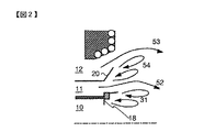
図2は、図1(b)に示す微粉炭燃焼バーナと対比するために示した従来の微粉炭燃焼バーナのノズル先端域の空気流を説明するための拡大図である。
【0039】
なお、図2に示す構成は、図1(a)に示すものと、案内板30が設けられていない点で相違する。
【0040】
次に本実施形態の燃焼動作を図1(a)と図1(b)に基いて説明する。
【0041】
微粉炭燃焼バーナの燃焼が始まると、微粉炭ノズル10と二次空気ノズル11を隔てる隔壁28の下流の空気はそれぞれのノズルから噴出する空気に巻き込まれるために、隔壁28の下流は圧力が低下し、下流から上流に向かって流れる循環流が形成される。隔壁28の先端部には保炎リング18を設けているので、一次空気と二次空気は分離され、循環流は拡大する。この循環流内には高温のガスが滞留するため、微粉炭の着火は進み、火炎の安定性は高まる。障害物32の下流では微粉炭は慣性力により、隔壁28近くに集まる。このため、循環流近くは微粉炭の濃度が高まり、微粉炭ノズルの出口近傍に微粉炭と一次空気による火炎が安定して形成される。さらにこの火炎内で酸素の消費が進むため、火炎内には酸素濃度の低い還元炎領域が広がり、NOx発生量を少なくすることがきる。また、着火が早まるため石炭の燃焼は進み、燃焼灰中の未燃焼分(以下、未燃分と記す)も減少する。さらに空気旋回羽根22、27を設けているので、二次空気と三次空気が旋回流として噴出し、その遠心力により保炎リング18下流の負圧は高まり、循環流はさらに拡大する。これによりバーナ近傍での二次空気や三次空気と微粉炭との混合が遅れ、火炎内の酸素濃度が減少するため、還元炎領域は広がる。
【0042】
本実施形態では、さらに、二次空気ノズル11から噴出する二次空気流52を二次空気ノズル11の外周側に偏向させる手段として、二次空気ノズル11の内周壁の先端部に案内板30を設けるようにした。二次空気は外周側方向に噴出し、二次空気や三次空気と微粉炭流との混合はいっそう遅れ、保炎リング18下流の循環流31は拡大する。この循環流域には下流から戻る高温ガス量が増えるので、微粉炭の着火が促進されて還元炎領域が広がる。このため、NOxや未燃分の発生をさらに減少させることができる。
【0043】
このときの燃焼状態の様子を、案内板30が設けられていない図2と対比して説明する。図2において、三次空気53は、テーパ状の円筒に形成されたガイドスリーブ20によって流路が曲げられ、外周側に噴出される。一方、二次空気ノズル11はガイドスリーブ20によりノズル出口部で流路が外周側に広がっている。空気は慣性により直進するため、二次空気52はバーナ軸方向に沿って流されやすい。このとき、ガイドスリーブ20に沿う領域の空気は二次空気52の流れに巻き込まれるため、二次空気の噴出方向とは逆方向に圧力の低下(以下、逆圧勾配と記す)が生じ、ガイドスリーブ20の下流には循環流54が形成される。この循環流54により三次空気53に中心に向かう流れが誘起され、三次空気53と微粉炭との混合が早まるので、還元炎領域が狭まる。
【0044】
それに対して、本実施形態では、図1(b)に示すように、案内板30により二次空気52は外周方向へ噴出する。このため、二次空気ノズル11と三次空気ノズル12を隔てるガイドスリーブ20の下流での循環流54の形成が阻止あるいは抑制される。また、外周方向へ噴出する二次空気52の運動量により、特に、二次空気52は三次空気53より外周側に向けて噴出するように構成したので、三次空気53はよりいっそう外周へ向かって流れる。このため、バーナ近傍での二次空気や三次空気と微粉炭との混合が遅れ、火炎内の還元炎領域が広がり、火炎内で発生するNOxを低減することができる。また、案内板30の先端はガイドスリーブ20の先端よりもバーナ軸方向に対し下流側に位置しているため、二次空気の流れは外周に流れやすくなり、ガイドスリーブ20の下流に循環流54ができにくい。
【0045】
なお、本実施形態では保炎リング18に付属する障害物65aによって二次空気ノズルの噴出口近傍の流路が狭められている。二次空気の噴出速度は高められるため、三次空気53と微粉炭との混合は遅らせることができる。
【0046】
このように、本実施形態によれば、二次空気ノズルに設けた案内板30によりに二次空気52は外周方向へ噴出する。また、二次空気ノズルと三次空気ノズルの間の隔壁下流での逆圧勾配が小さくなるため、二次空気ノズルの外周側にある三次空気ノズルから噴出する三次空気53も外周方向へ噴出する。このため、バーナ近傍での微粉炭と燃焼用空気との混合が抑制され、微粉炭はバーナ近傍では低酸素濃度雰囲気の状態で燃焼し、NOxの発生量を減少させることができる。一例として、図1に示すバーナ(ガイドスリーブ20と案内板30の先端とのバーナ軸方向の間隔10mm)と図2に示すバーナにおいて石炭供給量500kg/hで燃焼試験した結果を表1に示す。
【0047】
【表1】

このとき、図1に示すバーナの燃焼炉出口でのNOx濃度は103ppm(6%酸素濃度換算)であったのに対し、図2に示すバーナのNOx濃度は未燃分同一ベースで111ppm(6%酸素濃度換算)となり、本発明によるNOx発生量の低減効果が認められた。
【0049】
また、図1(c)は、図1(c)の案内板30を図1(b)のものより上流側に移動した場合の空気流を説明するノズル先端域の拡大図である。図1(c)に示すバーナのように、案内板30をガイドスリーブ20の先端よりもバーナ軸方向の上流側に移動した場合、二次空気52は図1(c)に示すように流れる。すなわち、二次空気52は案内板30により流れの向きを外周方向に変えられるが、外周方向への流れはガイドスリーブ20により妨げられる。このため、バーナから噴出する二次空気は図1(b)に示すように案内板30をガイドスリーブ20の先端よりもバーナ軸方向に下流側に設置した場合よりも軸方向に向かって流れる。このため、図1(c)に示すように、ガイドスリーブ20の下流には循環流54が形成されやすい。そのため、この循環流54により、三次空気53には中心軸方向への流れが誘起されるため、三次空気53と微粉炭との混合が早まり、還元炎領域が狭まる。一例として、図1(c)に示すバーナ(案内板30の先端がガイドスリーブ20の先端よりもバーナ軸方向に10mm上流に位置する)において石炭供給量500kg/hで燃焼試験した結果を表1に示す。このとき、図1(b)に示すバーナの燃焼炉出口でのNOx濃度は103ppm(6%酸素濃度換算)であったのに対し、図1(c)に示すバーナのNOx濃度は未燃分同一ベースで107ppm(6%酸素濃度換算)となり、案内板30をガイドスリーブ先端よりもバーナ軸方向に下流側に位置させた場合よりもNOx発生量が高まる。
【0050】
次に、本発明の第2の実施形態を図3を用いて説明する。
【0051】
図3は、本実施形態に係わる微粉炭燃焼バーナのノズル先端部の概略図である。
【0052】
本実施形態は、図1(a)と図1(b)に示す第1の実施形態と比べて、案内板30の角度55とガイドスリーブ20の角度56とを調整可能とした点が相違し、その他の構成は同一である。
【0053】
本実施形態によれば、案内板30の角度55とガイドスリーブ20の角度56とを調整することにより、供給される微粉炭、一次空気量や燃焼用空気量に応じて、第1の実施形態に比べてさらに最適な循環流域を形成し、効果的にNOxや未燃分を減少させることができる。
【0054】
このとき、案内板30の角度55は60度〜90度、より好ましくは80度〜90度にすることが望ましい。案内板30により二次空気52を外周方向へ噴出する。このため、二次空気ノズル11と三次空気ノズル12を隔てるガイドスリーブ20の下流での循環流54の形成が阻止あるいは抑制される。また、外周方向へ噴出する二次空気52の運動量により、特に、二次空気52は三次空気53より外周側に向けて噴出するように構成したので、三次空気53はよりいっそう外周へ向かって流れる。このため、バーナ近傍での二次空気や三次空気と微粉炭との混合が遅れ、火炎内の還元炎領域が広がることにより、火炎内で発生するNOxを低減することができる。
【0055】
次に、本発明の第3の実施形態を図4を用いて説明する。
【0056】
図4は、本実施形態に係わる微粉炭燃焼バーナのノズル先端部の概略図である。
【0057】
本実施形態は、同図に示すように、二次空気ノズル11から噴出する二次空気流を二次空気ノズルの外周側に誘導させる誘導部材として、二次空気ノズル11の出口域にテーパ状のリング61を設けたことを特徴とする。その他の構成は第1の実施形態と略同一構成である。
【0058】
本実施形態によれば、リング61はバーナ軸方向へ流れる二次空気52に対して障害物となる。リング61のテーパ部に沿って二次空気52が流れることにより、二次空気52に外周方向への流れが誘起され、一部はガイドスリーブ20に沿って流れる。このため、二次空気ノズル11と三次空気ノズル12を隔てるガイドスリーブ20の下流には二次空気52が流れる。ガイドスリーブ20の下流での逆圧勾配は生じにくくなるので、先に説明した循環流54の形成が阻止あるいは抑制される。また、外周方向へ噴出する二次空気52の運動量により、三次空気53はよりいっそう外周へ向かって流れる。このため、バーナ近傍での二次空気や三次空気と微粉炭との混合が遅れ、火炎内の酸素濃度が減少する。還元炎領域が広がることにより、火炎内で発生するNOxを低減することができる。
【0059】
次に、本発明の第4の実施形態を図5を用いて説明する。
【0060】
図5は、本実施形態に係わる微粉炭燃焼バーナのノズル先端部の概略図である。
【0061】
本実施形態は、同図に示すように、二次空気ノズル11から噴出する二次空気流を二次空気ノズルの外周側に誘導させる誘導部材として、二次空気ノズル11内またはノズル出口域に気体を外周に向かって噴出する気体噴出ノズル63を設けたことを特徴とする。気体には空気、燃焼排ガス、窒素などの不活性ガス、および水蒸気などを用いることができる。その他の構成は第1の実施形態と略同一構成である。
【0062】
本実施形態によれば、気体噴出ノズル63から噴出する気体の持つ運動量により、二次空気ノズル11から噴出する二次空気流に外周方向への流れが誘起され、一部はガイドスリーブ20に沿って流れる。運動量を高めるために、気体噴出ノズル63から噴出する気体の流速は二次空気ノズルから噴出する空気の流速よりも速いことが望ましい。この構成のバーナにおいて、二次空気52がガイドスリーブ20に沿って流れることにより、ガイドスリーブ20の下流での逆圧勾配は生じにくくなる。このため、ガイドスリーブ20の下流での先に説明した循環流54の形成が阻止あるいは抑制される。また、外周方向へ噴出する二次空気52の運動量により、三次空気53はよりいっそう外周へ向かって流れる。このため、バーナ近傍での二次空気や三次空気と微粉炭との混合が遅れ、火炎内の酸素濃度が減少する。還元炎領域が広がることにより、火炎内で発生するNOxを低減することができる。
【0063】
次に、本発明の第5の実施形態を図6を用いて説明する。
【0064】
図6は、本実施形態に係わる微粉炭燃焼バーナのノズル先端部の概略図である。
【0065】
本実施形態は、同図に示すように、二次空気ノズル11から噴出する二次空気流を二次空気ノズルの外周側に誘導させる手段として、二次空気ノズルの噴出口に二次空気旋回器としての旋回羽根64を設けたことを特徴とする。その他の構成は第1の実施形態と略同一構成である。
【0066】
本実施形態によれば、二次空気52は旋回羽根64により旋回流となり、遠心力により外周側に偏って流れる。このため、二次空気52はガイドスリーブ20に沿って流れることにより、ガイドスリーブ20の下流での逆圧勾配は生じにくくなる。このため、ガイドスリーブ20の下流での先に説明した循環流54の形成が阻止あるいは抑制される。また、外周方向へ噴出する二次空気52の運動量により、三次空気53はよりいっそう外周へ向かって流れる。このため、バーナ近傍での二次空気や三次空気と微粉炭との混合が遅れ、火炎内の酸素濃度が減少する。還元炎領域が広がることにより、火炎内で発生するNOxを低減することができる。
【0067】
以上のごとく、上記の各実施形態の微粉炭燃焼バーナによれば、二次空気ノズルから噴出する二次空気流を二次空気ノズルの外周側へ偏向させる手段を設けたので、二次空気ノズルとその外周側に位置する三次空気ノズルとの隔壁の下流側には循環流が形成されにくくなる。循環流の領域では流れの噴出方向とは逆方向の圧力降下(逆圧勾配)があり、循環流に沿って流れる空気は逆圧勾配により流れの方向が変わる。微粉炭燃焼バーナの流れでは、二次空気ノズルと三次空気ノズルとの隔壁下流に循環流が形成されると、三次空気の流れは循環流により微粉炭流側へと流れやすくなる。ところが、上記各実施形態のものでは、二次空気を外周方向へ噴出することで、二次空気ノズルと三次空気ノズルとの隔壁下流に循環流が形成しにくくしているため、バーナ近くでは三次空気は微粉炭流と離れて流れる。
【0068】
また、二次空気を外周に噴出することにより、一次空気と二次空気がバーナ近くで離れて流れる。このため、微粉炭ノズルと二次空気ノズルの隔壁下流に二次空気ノズルから噴出する二次空気が流入しにくくなるので逆圧勾配が強まり、循環流は広がる。この一次空気と二次空気流との間に形成される循環流内には高温の気体が滞留し、微粉炭の着火や火炎の安定化に寄与する。循環流が広がることにより、二次空気による循環流内の冷却が弱まり、温度は上昇する。このため、微粉炭の着火は促進される。着火により酸素の消費が進むため、火炎内に形成される酸素濃度の低い領域は拡大し、NOxの発生量は減少すると共に、燃焼灰中の未燃分は減少する。
【0069】
さらにまた、微粉炭の着火や火炎の安定性が向上することで、燃焼に必要な距離は短くなり、燃焼装置本体を小型化できる効果も得られる。さらに、低負荷での燃焼時のように微粉炭の濃度が減少する場合でも火炎が安定なため、微粉炭燃焼バーナでの微粉炭専焼の可能範囲は広がる。
【0070】
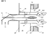
次に、本発明の第6の実施形態を図7を用いて説明する。
【0071】
図7は、本実施形態に係わる微粉炭燃焼バーナの概略図である。
【0072】
本実施形態は、同図に示すように、二次空気ノズル11から噴出する二次空気流を二次空気ノズル11の外周側に偏向させると共に、隔壁28の先端部に、一次空気と二次空気の流れに対し垂直な平面を有するリング30を設けることを特徴とする。その他の構成は第1の実施形態と略同一構成である。
【0073】
同図において、リング30は、微粉炭ノズル10側に形成される内部リング301と二次空気ノズル11側に形成される外部リング302から形成される。リング30により一次空気と二次空気には乱れが生じ、リング30の下流に形成される循環流は発達する。本実施形態では、内部リング301と外部リング302の位置をバーナ軸方向に離して設ける。その結果、リング30の下流に形成される循環流は微粉炭流側と二次空気流側でバーナ軸方向にずれて形成される。軸方向に同位置に循環流が2つ形成される場合に比べ、循環流は軸方向へ長くなる。このため、循環流31には下流側から気体が環流する。
【0074】
また、外部リング302により二次空気を外周に噴出する。このため、一次空気と二次空気がバーナ近くで離れて流れる。このため、微粉炭ノズルと二次空気ノズルの隔壁下流に二次空気ノズルから噴出する二次空気が流入しにくくなるので逆圧勾配が強まり、循環流は広がる。この一次空気と二次空気流との間に形成される循環流内には高温の気体が滞留し、微粉炭の着火や火炎の安定化に寄与する。循環流が広がることで、二次空気による循環流内の冷却が弱まり、温度は上昇する。このため、微粉炭の着火は促進される。着火により酸素の消費が進むため、火炎内に形成される酸素濃度の低い領域は拡大し、NOxの発生量は減少すると共に、燃焼灰中の未燃分は減少する。また、微粉炭の着火や火炎の安定性が向上することで、燃焼に必要な距離は短くなり、燃焼装置本体を小型化できる効果も得られる。さらに、低負荷での燃焼時のように微粉炭の濃度が減少する場合でも火炎が安定なため、微粉炭燃焼バーナでの微粉炭専焼の可能範囲は広がる。
【0075】
さらに、外部リング302により二次空気を外周に噴出することで、二次空気ノズルとその外周側に位置する三次空気ノズルとの隔壁の下流側には循環流が形成されにくくなる。循環流の領域では流れの噴出方向とは逆方向の圧力降下(逆圧勾配)があり、循環流に沿って流れる空気は逆圧勾配により流れの方向が変わる。微粉炭燃焼バーナの流れでは、二次空気ノズルと三次空気ノズルとの隔壁下流に循環流が形成されると、三次空気の流れは循環流により微粉炭流側へと流れやすくなる。ところが、本発明では二次空気を外周方向へ噴出することで、二次空気ノズルと三次空気ノズルとの隔壁下流に循環流が形成しにくくしているため、バーナ近くでは三次空気は微粉炭流と離れて流れる。
【0076】
次に、本発明の第7の実施形態を図8を用いて説明する。
【0077】
図8は、本実施形態に係わる微粉炭燃焼バーナの概略図である。
【0078】
本実施形態は、同図に示すように、二次空気ノズル11から噴出する二次空気流を二次空気ノズル11の外周側に偏向させると共に、隔壁28の下流に循環流を形成する手段として、隔壁28の先端部に設けられ、リング30の二次空気ノズル11内周壁側にリング30の肉厚部(例えば10mm厚)303を設けることを特徴とする。また、一次空気ノズル10内に障害物32を有さない。微粉炭の着火性が良好な場合は、図8に示すように障害物32を有さなくても良い。その他の構成は第6の実施形態と略同一構成である。
【0079】
本実施形態によれば、肉厚部303によって二次空気ノズルの流路が狭められ、二次空気はこの肉厚部303を通過するときに流速を速められる。流速が高まった状態で二次空気は外部リング302に衝突するため、衝突により二次空気に誘起される外周方向への流速は高い。その結果、第6の実施形態のときよりも二次空気の外周方向の流速は強まる。このため、微粉炭ノズルと二次空気ノズルの隔壁下流の循環流は広がり、この循環流内の温度上昇により微粉炭の着火は促進される。また、二次空気を外周方向へ噴出することで、二次空気ノズルと三次空気ノズルとの隔壁下流に循環流が形成しにくくしているため、バーナ近くでは三次空気は微粉炭流と離れて流れる。このため、火炎内に形成される酸素濃度の低い領域は拡大し、NOxの発生量は減少すると共に、燃焼灰中の未燃分は減少する。
【0080】
なお、第6および第7の各実施形態において、リング30の外部リング302をバーナの周方向に一様なリングとしたが、必要に応じて、外部リング302の先端を周方向に沿って凹凸状に切り欠きを形成してもよい。切り欠きをつけることにより、リングの熱変形を緩和できる。また、外部リング302の下流側の乱れが増大し、循環流が発達しやすくなる。また、この凹凸状の切り欠きは外部リング302だけでなく、内部リング301に設けてもよい。
【0081】
次に本発明の第8の実施形態を図9を用いて説明する。
【0082】
図9は、本実施形態に係わる微粉炭燃焼バーナの概略図である。
【0083】
本実施形態は、同図に示すように、二次空気ノズル11から噴出する二次空気流を二次空気ノズル11の外周側に偏向させると共に、隔壁28の下流に循環流を形成する手段としてリング30を設ける。また、二次空気ノズル11の出口近傍の流路を狭める手段として、障害物65bを二次空気ノズルの外周壁の周方向に設けることを特徴とする。また、一次空気ノズル10内の障害物32は絞り部17近くに設けられる。図1に対し図9に示すように、障害物32を上流側に設けても隔壁28近くに集められる。その他の構成は第6の実施形態と略同一構成である。
【0084】
本実施形態によれば、二次空気は障害物65bで流速が速められると共に障害物65bの下流側の流路拡大部で空気流が乱され、一定の乱れを発生させることができる。このため、微粉炭ノズルと二次空気ノズルの隔壁下流の循環流は広がり、この循環流内の温度上昇により微粉炭の着火は促進される。また、障害物65bで流速の増した二次空気は外部リング302に衝突し、外周方向へ噴出することで、二次空気ノズルと三次空気ノズルとの隔壁下流に循環流が形成しにくくなる。このため、三次空気は循環流により流れの方向が変えられることがなくなり、バーナ近くでは三次空気は微粉炭流と離れて流れる。このため、火炎内に形成される酸素濃度の低い領域は拡大し、NOxの発生量は減少すると共に、燃焼灰中の未燃分は減少する。
【0085】
【発明の効果】
上記のごとく、本発明によれば、二次空気ノズルから噴出する二次空気流を二次空気ノズルの外周側に偏向させる手段を設けたので、二次空気は外周方向へ流れる。二次空気ノズルと三次空気ノズルとの隔壁下流に循環流が形成しにくくなる。このため、三次空気は循環流により流れの方向が変えられることがなくなり、バーナ近くでは三次空気は微粉炭流と離れて流れる。また、二次空気が外周方向へ流れることで、微粉炭ノズルと二次空気ノズルの隔壁の下流側に形成される循環流に二次空気ノズルから直接二次空気が流入しにくくなるので、逆圧勾配は強まり、この循環流は広がる。その結果、バーナ近傍では微粉炭と三次空気との混合が抑制され、また、微粉炭の着火が促進される。このため、微粉炭はバーナ近傍で低い酸素濃度の状態で燃焼し、NOxの発生量を低減できる。また、微粉炭の着火が促進されるので、燃焼灰中の未燃分が低減することができる。
【図面の簡単な説明】
【図1】本発明の第1の実施形態に係わる微粉炭燃焼バーナの概略図である。
【図2】第1の実施形態と対比するために示した従来技術に係わる微粉炭燃焼バーナのノズル先端部の概略図である。
【図3】本発明の第2の実施形態に係わる微粉炭燃焼バーナの概略図である。
【図4】本発明の第3の実施形態に係わる微粉炭燃焼バーナのノズル先端部の概略図である。
【図5】本発明の第4の実施形態に係わる微粉炭燃焼バーナのノズル先端部の概略図である。
【図6】本発明の第5の実施形態に係わる微粉炭燃焼バーナのノズル先端部の概略図である。
【図7】本発明の第6の実施形態に係わる微粉炭燃焼バーナの概略図である。
【図8】本発明の第7の実施形態に係わる微粉炭燃焼バーナの概略図である。
【図9】本発明の第8の実施形態に係わる微粉炭燃焼バーナの概略図である。
【符号の説明】
10 微粉炭ノズル
11 二次空気ノズル
12 三次空気ノズル
30 案内板
301 内部リング
302 外部リング
303 肉厚部
31 循環流
61 リング
63 気体放出ノズル
64 旋回羽根
65a,65b 障害物[0001]
BACKGROUND OF THE INVENTION
The present invention relates to a burner that burns pulverized coal by airflow conveyance, and particularly relates to a pulverized coal combustion burner suitable for reducing the concentration of nitrogen oxides (hereinafter referred to as NOx).
[0002]
[Prior art]
In general, in a combustion burner, suppression of NOx generated during combustion becomes a problem. In particular, coal has a higher nitrogen content than gaseous and liquid fuels. For this reason, it is more important to reduce NOx generated during combustion of the pulverized coal combustion burner than in the case of gaseous fuel or liquid fuel.
[0003]
Most of the NOx generated during combustion of pulverized coal is NOx generated by oxidation of nitrogen contained in coal, so-called fuel NOx. In order to reduce this NOx, various burner structures and combustion methods have been studied conventionally.
[0004]
As one of the combustion methods, there is a method of reducing NOx by forming a low oxygen concentration region in the flame. For example, in JP-A-1-305306 (USP 4930430), JP-A-3-211304, JP-A-3-110308, USP 5231937, USP 5680823, etc., a flame in a low oxygen concentration atmosphere is formed and coal is completely used. A combustion method and a structure including an air nozzle that ejects air to the outside centered on a fuel nozzle that conveys pulverized coal in an airflow are disclosed. According to these prior arts, a reducing flame region having a low oxygen concentration is formed inside the flame, and the NOx reduction reaction proceeds in the reducing flame region to reduce the amount of NOx generated in the flame. JP-A-3-211304, JP-A-3-110308, and USP 5231937 describe that a flame holding ring is provided at the tip of a pulverized coal nozzle to stabilize the flame. According to these conventional techniques, by providing a flame holding ring or an obstacle at the tip of the pulverized coal nozzle, a circulation flow is formed on the downstream side of the tip of the pulverized coal nozzle. Since stagnation occurs, the pulverized coal is ignited and the stability of the flame can be improved.
[0005]
[Problems to be solved by the invention]
However, the above prior art is still not sufficient for suppressing NOx generation.
[0006]
An object of the present invention is to provide a pulverized coal combustion burner that can improve the above-mentioned problems of the prior art and further reduce the amount of NOx generated.
[0007]
[Means for Solving the Problems]
The present invention employs the following means in order to solve the above problems.
[0008]
A secondary air nozzle for ejecting secondary air is provided concentrically on the outer periphery of the pulverized coal nozzle for ejecting a mixture of pulverized coal and primary air, and tertiary air for ejecting tertiary air to the outer periphery of the secondary air nozzle. In the pulverized coal combustion burner in which the nozzles are provided concentrically, and the expanded portion is provided at the tip of the outer peripheral wall of the secondary air nozzle,
An obstacle having a plane substantially perpendicular to the flow of primary air and a guide plate having a plane substantially perpendicular to the flow of secondary air are provided at the tip of the partition wall separating the pulverized coal nozzle and the secondary air nozzle,
The plane of the obstacle is located on the upstream side in the axial direction of the pulverized coal nozzle from the plane of the guide plate,
The flat surface of the guide plate is provided so as to protrude further downstream in the axial direction of the pulverized coal nozzle than the tip of the expanded pipe portion.It is characterized by that.
[0009]
Thus, since the secondary air nozzle and the tertiary air nozzle are arranged concentrically on the outer periphery of the pulverized coal nozzle, a reduction flame region having a low oxygen concentration is formed by the primary air to suppress the generation of NOx, Tertiary air is mixed on the downstream side of the reducing flame region to form an oxidizing flame, complete combustion is achieved, the mixing of secondary air and tertiary air is slowed down to form a reducing flame region, and NOx is generated. The suppression effect can be enhanced.
[0010]
In addition, pulverized coal itself has poor ignitability, and in order to form a stable flame, it is desirable to draw the high-temperature combustion gas downstream of the flame close to the outlet of the pulverized coal nozzle. Since a low-pressure part is formed on the downstream side of the front end of the partition wall separating the nozzle and the secondary air nozzle to form a circulating flow, the high-temperature combustion gas is drawn back.
[0011]
Further, since the secondary air flows to the outer periphery along the expanded pipe portion at the outer peripheral end of the secondary air nozzle, the circulation flow formed on the downstream side of the partition wall separating the pulverized coal nozzle and the secondary air nozzle is large. Therefore, mixing of secondary air and pulverized coal can be delayed. Furthermore, since the circulation flow becomes large, high-temperature combustion gas flows into the circulation flow, and the ignitability of pulverized coal is improved.
[0012]
Also, move the secondary air flow toward the outer periphery.Guide plateTherefore, it is possible to delay the mixing of the secondary air, tertiary air and pulverized coal to enlarge the reduction flame region, and the circulation flow downstream of the partition wall separating the pulverized coal nozzle and the secondary air nozzle is Since it becomes large, the ignitability of pulverized coal is improved, and oxygen consumption is accelerated, so that the reducing flame region can be enlarged.
[0013]
Also,By providing a plane that is substantially perpendicular to the flow of secondary air on the guide plateThe effect of directing the secondary air to the outside increases, and is effective in delaying the mixing of the secondary air and pulverized coal.
Further, an obstacle having a plane substantially perpendicular to the flow of primary air and a guide plate having a plane substantially perpendicular to the flow of secondary air are provided at the tip of the partition wall separating the pulverized coal nozzle and the secondary air nozzle, By arranging the obstacle plane on the upstream side in the axial direction of the pulverized coal nozzle from the plane of the guide plate, a circulation flow is formed after the obstacle and the guide plate, respectively, and this circulation flow extends in the burner axial direction. For this reason, since high-temperature combustion gas flows in from the downstream side, the temperature of the circulating flow rises and the ignitability of pulverized coal is improved.
[0017]
Moreover, in the pulverized coal combustion burner according to
[0018]
Thus, by providing a slit in the guide plate, thermal deformation of the guide plate can be suppressed.
[0021]
Claims1In the pulverized coal combustion burner according to
[0022]
Obstacles like thisOf the signboardObstacles by providing notches along the circumferential direction at the tip,Guide plateCan alleviate thermal deformation. Also obstacles,Guide plateThe turbulence on the downstream side increases, and the circulation flow easily develops.
[0035]
DETAILED DESCRIPTION OF THE INVENTION
In the following, a first embodiment of the present invention will be described with reference to FIGS.
[0036]
FIG. 1A is a schematic view of a pulverized coal combustion burner according to the present embodiment, and FIGS. 1B and 1C are enlarged views for explaining the air flow in the nozzle tip region shown in FIG. It is.
[0037]
In these drawings, 10 is a pulverized coal nozzle connected to a conveyance pipe (not shown) on the upstream side and supplying and conveying pulverized coal together with primary air, 11 is a secondary air nozzle for ejecting secondary air, A flow path is formed concentrically on the outer periphery of the pulverized
[0038]
FIG. 2 is an enlarged view for explaining the air flow in the nozzle tip region of the conventional pulverized coal combustion burner shown for comparison with the pulverized coal combustion burner shown in FIG.
[0039]
2 differs from that shown in FIG. 1A in that the
[0040]
Next, the combustion operation of the present embodiment will be described with reference to FIGS. 1 (a) and 1 (b).
[0041]
When the combustion of the pulverized coal combustion burner starts, the air downstream of the
[0042]
In the present embodiment, as a means for deflecting the
[0043]
The state of the combustion state at this time will be described in comparison with FIG. 2 in which the
[0044]
On the other hand, in this embodiment, as shown in FIG.1 (b), the
[0045]
In the present embodiment, the flow path near the outlet of the secondary air nozzle is narrowed by the
[0046]
Thus, according to the present embodiment, the
[0047]
[Table 1]
At this time, the NOx concentration at the burner outlet of the burner shown in FIG. 1 was 103 ppm (6% oxygen concentration conversion), whereas the NOx concentration of the burner shown in FIG. % Oxygen concentration conversion), and the NOx generation amount reducing effect according to the present invention was recognized.
[0049]
FIG. 1 (c) is an enlarged view of the nozzle tip region for explaining the air flow when the
[0050]
Next, a second embodiment of the present invention will be described with reference to FIG.
[0051]
FIG. 3 is a schematic view of the nozzle tip of the pulverized coal combustion burner according to the present embodiment.
[0052]
This embodiment is different from the first embodiment shown in FIGS. 1A and 1B in that the
[0053]
According to the present embodiment, by adjusting the
[0054]
At this time, the
[0055]
Next, a third embodiment of the present invention will be described with reference to FIG.
[0056]
FIG. 4 is a schematic view of the nozzle tip of the pulverized coal combustion burner according to this embodiment.
[0057]
In the present embodiment, as shown in the figure, the outlet region of the
[0058]
According to the present embodiment, the
[0059]
Next, a fourth embodiment of the present invention will be described with reference to FIG.
[0060]
FIG. 5 is a schematic view of the nozzle tip of the pulverized coal combustion burner according to this embodiment.
[0061]
In this embodiment, as shown in the figure, as a guide member for guiding the secondary air flow ejected from the
[0062]
According to the present embodiment, due to the momentum of the gas ejected from the
[0063]
Next, a fifth embodiment of the present invention will be described with reference to FIG.
[0064]
FIG. 6 is a schematic view of the nozzle tip of the pulverized coal combustion burner according to this embodiment.
[0065]
In the present embodiment, as shown in the figure, as a means for guiding the secondary air flow ejected from the
[0066]
According to the present embodiment, the
[0067]
As described above, according to the pulverized coal combustion burner of each of the above embodiments, since the means for deflecting the secondary air flow ejected from the secondary air nozzle to the outer peripheral side of the secondary air nozzle is provided, the secondary air nozzle In addition, a circulating flow is less likely to be formed on the downstream side of the partition wall with the tertiary air nozzle located on the outer peripheral side thereof. In the region of the circulation flow, there is a pressure drop (counterpressure gradient) opposite to the flow ejection direction, and the flow direction of the air flowing along the circulation flow is changed by the counter pressure gradient. In the flow of the pulverized coal combustion burner, when a circulation flow is formed downstream of the partition wall between the secondary air nozzle and the tertiary air nozzle, the flow of the tertiary air is likely to flow to the pulverized coal flow side by the circulation flow. However, in the above embodiments, the secondary air is ejected in the outer circumferential direction, so that it is difficult to form a circulation flow downstream of the partition wall between the secondary air nozzle and the tertiary air nozzle. Air flows away from the pulverized coal stream.
[0068]
Further, by ejecting the secondary air to the outer periphery, the primary air and the secondary air flow away from each other near the burner. For this reason, since the secondary air ejected from the secondary air nozzle is less likely to flow downstream from the partition wall between the pulverized coal nozzle and the secondary air nozzle, the reverse pressure gradient is increased and the circulation flow is expanded. High-temperature gas stays in the circulating flow formed between the primary air and the secondary air flow, and contributes to the ignition of pulverized coal and the stabilization of the flame. By spreading the circulation flow, the cooling in the circulation flow by the secondary air is weakened, and the temperature rises. For this reason, the ignition of pulverized coal is promoted. Since the consumption of oxygen proceeds due to ignition, the region of low oxygen concentration formed in the flame expands, the amount of NOx generated decreases, and the unburned content in the combustion ash decreases.
[0069]
Furthermore, since the ignition of the pulverized coal and the stability of the flame are improved, the distance required for the combustion is shortened, and the effect of reducing the size of the combustion apparatus main body can be obtained. Furthermore, since the flame is stable even when the concentration of pulverized coal is reduced as in the case of combustion at a low load, the possible range of pulverized coal combustion in the pulverized coal combustion burner is expanded.
[0070]
Next, a sixth embodiment of the present invention will be described with reference to FIG.
[0071]
FIG. 7 is a schematic view of a pulverized coal combustion burner according to this embodiment.
[0072]
In this embodiment, as shown in the figure, the secondary air flow ejected from the
[0073]
In the figure, the
[0074]
Further, secondary air is ejected to the outer periphery by the
[0075]
Further, by ejecting the secondary air to the outer periphery by the
[0076]
Next, a seventh embodiment of the present invention will be described with reference to FIG.
[0077]
FIG. 8 is a schematic view of a pulverized coal combustion burner according to the present embodiment.
[0078]
In this embodiment, as shown in the figure, as a means for deflecting the secondary air flow ejected from the
[0079]
According to this embodiment, the flow path of the secondary air nozzle is narrowed by the
[0080]
In each of the sixth and seventh embodiments, the
[0081]
Next, an eighth embodiment of the present invention will be described with reference to FIG.
[0082]
FIG. 9 is a schematic view of a pulverized coal combustion burner according to this embodiment.
[0083]
In this embodiment, as shown in the figure, as a means for deflecting the secondary air flow ejected from the
[0084]
According to the present embodiment, the flow rate of the secondary air is increased by the
[0085]
【The invention's effect】
As described above, according to the present invention, since the means for deflecting the secondary air flow ejected from the secondary air nozzle toward the outer peripheral side of the secondary air nozzle is provided, the secondary air flows in the outer peripheral direction. It becomes difficult to form a circulation flow downstream of the partition wall between the secondary air nozzle and the tertiary air nozzle. For this reason, the flow direction of the tertiary air is not changed by the circulation flow, and the tertiary air flows away from the pulverized coal flow near the burner. Also, since the secondary air flows in the outer circumferential direction, the secondary air is less likely to flow directly from the secondary air nozzle into the circulation flow formed on the downstream side of the partition wall between the pulverized coal nozzle and the secondary air nozzle. The pressure gradient becomes stronger, and this circulation flow spreads. As a result, mixing of pulverized coal and tertiary air is suppressed in the vicinity of the burner, and ignition of the pulverized coal is promoted. For this reason, pulverized coal burns in the state of a low oxygen concentration near the burner, and the amount of NOx generated can be reduced. Moreover, since the ignition of pulverized coal is promoted, the unburned content in the combustion ash can be reduced.
[Brief description of the drawings]
FIG. 1 is a schematic view of a pulverized coal combustion burner according to a first embodiment of the present invention.
FIG. 2 is a schematic view of the nozzle tip of a pulverized coal combustion burner according to the prior art shown for comparison with the first embodiment.
FIG. 3 is a schematic view of a pulverized coal combustion burner according to a second embodiment of the present invention.
FIG. 4 is a schematic view of a nozzle tip portion of a pulverized coal combustion burner according to a third embodiment of the present invention.
FIG. 5 is a schematic view of a nozzle tip of a pulverized coal combustion burner according to a fourth embodiment of the present invention.
FIG. 6 is a schematic view of a nozzle tip portion of a pulverized coal combustion burner according to a fifth embodiment of the present invention.
FIG. 7 is a schematic view of a pulverized coal combustion burner according to a sixth embodiment of the present invention.
FIG. 8 is a schematic view of a pulverized coal combustion burner according to a seventh embodiment of the present invention.
FIG. 9 is a schematic view of a pulverized coal combustion burner according to an eighth embodiment of the present invention.
[Explanation of symbols]
10 Pulverized coal nozzle
11 Secondary air nozzle
12 Tertiary air nozzle
30 Information board
301 inner ring
302 outer ring
303 Thick part
31 Circulating flow
61 ring
63 Gas discharge nozzle
64 Swivel blade
65a, 65b Obstacle
Claims (4)
前記微粉炭ノズルと前記二次空気ノズルを隔てる隔壁先端部に一次空気の流れに対し略垂直な平面を有する障害物と二次空気の流れに対し略垂直な平面を有する案内板を設け、
前記障害物の平面は、前記案内板の平面より前記微粉炭ノズルの軸方向の上流側に位置し、
前記案内板の平面は、前記拡管部の先端よりも前記微粉炭ノズルの軸方向の下流側に突出させて設けたことを特徴とする微粉炭燃焼バーナ。A secondary air nozzle for ejecting secondary air is provided concentrically on the outer periphery of the pulverized coal nozzle for ejecting a mixture of pulverized coal and primary air, and tertiary air for ejecting tertiary air to the outer periphery of the secondary air nozzle. In the pulverized coal combustion burner in which the nozzles are provided concentrically, and the expanded portion is provided at the tip of the outer peripheral wall of the secondary air nozzle,
An obstacle having a plane substantially perpendicular to the flow of primary air and a guide plate having a plane substantially perpendicular to the flow of secondary air are provided at the tip of the partition wall separating the pulverized coal nozzle and the secondary air nozzle,
The plane of the obstacle is located on the upstream side in the axial direction of the pulverized coal nozzle from the plane of the guide plate,
The pulverized coal combustion burner is characterized in that a flat surface of the guide plate is provided so as to protrude downstream in the axial direction of the pulverized coal nozzle from the tip of the expanded pipe portion .
Priority Applications (1)
| Application Number | Priority Date | Filing Date | Title |
|---|---|---|---|
| JP30551498A JP3986182B2 (en) | 1998-10-27 | 1998-10-27 | Pulverized coal combustion burner and combustion apparatus provided with the same |
Applications Claiming Priority (1)
| Application Number | Priority Date | Filing Date | Title |
|---|---|---|---|
| JP30551498A JP3986182B2 (en) | 1998-10-27 | 1998-10-27 | Pulverized coal combustion burner and combustion apparatus provided with the same |
Publications (3)
| Publication Number | Publication Date |
|---|---|
| JP2000130710A JP2000130710A (en) | 2000-05-12 |
| JP2000130710A5 JP2000130710A5 (en) | 2005-03-10 |
| JP3986182B2 true JP3986182B2 (en) | 2007-10-03 |
Family
ID=17946081
Family Applications (1)
| Application Number | Title | Priority Date | Filing Date |
|---|---|---|---|
| JP30551498A Expired - Lifetime JP3986182B2 (en) | 1998-10-27 | 1998-10-27 | Pulverized coal combustion burner and combustion apparatus provided with the same |
Country Status (1)
| Country | Link |
|---|---|
| JP (1) | JP3986182B2 (en) |
Cited By (4)
| Publication number | Priority date | Publication date | Assignee | Title |
|---|---|---|---|---|
| CN101949542A (en) * | 2010-04-14 | 2011-01-19 | 华中科技大学 | Three-layered secondary air low nitrogen oxide swirl burner |
| CN101639217B (en) * | 2008-08-01 | 2011-09-21 | 北京光耀能源技术股份有限公司 | Two-stage speed-down pulverized coal burner |
| KR20190132349A (en) | 2018-05-17 | 2019-11-27 | 미츠비시 히타치 파워 시스템즈 가부시키가이샤 | Support sleeve protection member and solid fuel burner having the same |
| US11692705B2 (en) | 2019-05-13 | 2023-07-04 | Mitsubishi Heavy Industries, Ltd. | Solid fuel burner, boiler equipment, nozzle unit for solid fuel burner, and guide vane unit |
Families Citing this family (13)
| Publication number | Priority date | Publication date | Assignee | Title |
|---|---|---|---|---|
| KR100376619B1 (en) * | 2000-09-25 | 2003-03-19 | 두산중공업 주식회사 | Low Nitrogen Oxide Coal Firing Burner |
| JP4309853B2 (en) | 2005-01-05 | 2009-08-05 | バブコック日立株式会社 | Solid fuel burner and combustion method |
| AU2007301377B2 (en) * | 2006-09-27 | 2011-02-03 | Mitsubishi Power, Ltd. | Burner, and combustion equipment and boiler comprising burner |
| JP4946406B2 (en) * | 2006-12-07 | 2012-06-06 | 株式会社Ihi | Burner for pulverized coal combustion |
| JP5535522B2 (en) * | 2009-05-22 | 2014-07-02 | 三菱重工業株式会社 | Coal fired boiler |
| JP5386230B2 (en) * | 2009-05-22 | 2014-01-15 | 三菱重工業株式会社 | Fuel burner and swirl combustion boiler |
| JP5535521B2 (en) * | 2009-05-22 | 2014-07-02 | 三菱重工業株式会社 | Coal fired boiler |
| CN102500551A (en) * | 2011-09-29 | 2012-06-20 | 华中科技大学 | Device for separating rough and fine coal powder in pipeline |
| JP5443525B2 (en) * | 2012-02-16 | 2014-03-19 | ザ・バブコック・アンド・ウイルコックス・カンパニー | NOx emission reduction method for central air jet burner |
| WO2019022059A1 (en) * | 2017-07-25 | 2019-01-31 | 株式会社Ihi | Powder fuel burner |
| WO2019131335A1 (en) * | 2017-12-26 | 2019-07-04 | 三菱日立パワーシステムズ株式会社 | Solid fuel burner and flame stabilizer for solid fuel burner |
| WO2020234965A1 (en) * | 2019-05-20 | 2020-11-26 | 三菱日立パワーシステムズ株式会社 | Solid fuel burner |
| WO2022180735A1 (en) * | 2021-02-25 | 2022-09-01 | 太平洋セメント株式会社 | Cement kiln burner and method for operating same |
-
1998
- 1998-10-27 JP JP30551498A patent/JP3986182B2/en not_active Expired - Lifetime
Cited By (4)
| Publication number | Priority date | Publication date | Assignee | Title |
|---|---|---|---|---|
| CN101639217B (en) * | 2008-08-01 | 2011-09-21 | 北京光耀能源技术股份有限公司 | Two-stage speed-down pulverized coal burner |
| CN101949542A (en) * | 2010-04-14 | 2011-01-19 | 华中科技大学 | Three-layered secondary air low nitrogen oxide swirl burner |
| KR20190132349A (en) | 2018-05-17 | 2019-11-27 | 미츠비시 히타치 파워 시스템즈 가부시키가이샤 | Support sleeve protection member and solid fuel burner having the same |
| US11692705B2 (en) | 2019-05-13 | 2023-07-04 | Mitsubishi Heavy Industries, Ltd. | Solid fuel burner, boiler equipment, nozzle unit for solid fuel burner, and guide vane unit |
Also Published As
| Publication number | Publication date |
|---|---|
| JP2000130710A (en) | 2000-05-12 |
Similar Documents
| Publication | Publication Date | Title |
|---|---|---|
| JP3344694B2 (en) | Pulverized coal combustion burner | |
| JP3986182B2 (en) | Pulverized coal combustion burner and combustion apparatus provided with the same | |
| JP3099109B2 (en) | Pulverized coal burner | |
| JP3343855B2 (en) | Pulverized coal combustion burner and combustion method of pulverized coal combustion burner | |
| JPH0820047B2 (en) | Low NOx short flame burner | |
| JP3924089B2 (en) | Pulverized coal burner and combustion apparatus using pulverized coal burner | |
| JP4309853B2 (en) | Solid fuel burner and combustion method | |
| JP3643461B2 (en) | Pulverized coal combustion burner and combustion method thereof | |
| JP3073396B2 (en) | Pulverized coal burner | |
| JP3888619B2 (en) | Gas turbine combustor premixing device | |
| JP2001355832A (en) | Air port structure | |
| JP3338599B2 (en) | Pulverized coal combustion method, pulverized coal combustion apparatus, and pulverized coal combustion burner | |
| WO2023127121A1 (en) | Cyclone burner, cyclone burner unit, and modification method for cyclone burner | |
| JP2003343817A (en) | SWIRL TYPE LOW NOx COMBUSTOR | |
| JP2943887B2 (en) | Burner with low nitrogen oxide generation | |
| JPH09318014A (en) | Pulverized coal combustion burner | |
| JP2943886B2 (en) | Burner with low nitrogen oxide generation | |
| JPH0771715A (en) | Low nox combustion device | |
| JP2019132560A (en) | Combustion burner | |
| JPS6086311A (en) | Low nox boiler | |
| JPS62288406A (en) | Fine coal burner | |
| JP2006057961A (en) | Burner for combustion, and combustion apparatus having burner for combustion | |
| JPS63140208A (en) | Pulverized coal burner | |
| JPH0719426A (en) | Burner device | |
| JPH06313523A (en) | Burner reduced in generation of nitrogen oxide |
Legal Events
| Date | Code | Title | Description |
|---|---|---|---|
| A521 | Written amendment |
Free format text: JAPANESE INTERMEDIATE CODE: A523 Effective date: 20040406 |
|
| A621 | Written request for application examination |
Free format text: JAPANESE INTERMEDIATE CODE: A621 Effective date: 20040406 |
|
| A131 | Notification of reasons for refusal |
Free format text: JAPANESE INTERMEDIATE CODE: A131 Effective date: 20060620 |
|
| A521 | Written amendment |
Free format text: JAPANESE INTERMEDIATE CODE: A523 Effective date: 20060821 |
|
| A131 | Notification of reasons for refusal |
Free format text: JAPANESE INTERMEDIATE CODE: A131 Effective date: 20070213 |
|
| A521 | Written amendment |
Free format text: JAPANESE INTERMEDIATE CODE: A523 Effective date: 20070416 |
|
| TRDD | Decision of grant or rejection written | ||
| A01 | Written decision to grant a patent or to grant a registration (utility model) |
Free format text: JAPANESE INTERMEDIATE CODE: A01 Effective date: 20070703 |
|
| A61 | First payment of annual fees (during grant procedure) |
Free format text: JAPANESE INTERMEDIATE CODE: A61 Effective date: 20070710 |
|
| R150 | Certificate of patent or registration of utility model |
Free format text: JAPANESE INTERMEDIATE CODE: R150 |
|
| FPAY | Renewal fee payment (event date is renewal date of database) |
Free format text: PAYMENT UNTIL: 20100720 Year of fee payment: 3 |
|
| FPAY | Renewal fee payment (event date is renewal date of database) |
Free format text: PAYMENT UNTIL: 20100720 Year of fee payment: 3 |
|
| S111 | Request for change of ownership or part of ownership |
Free format text: JAPANESE INTERMEDIATE CODE: R313117 |
|
| FPAY | Renewal fee payment (event date is renewal date of database) |
Free format text: PAYMENT UNTIL: 20100720 Year of fee payment: 3 |
|
| R350 | Written notification of registration of transfer |
Free format text: JAPANESE INTERMEDIATE CODE: R350 |
|
| FPAY | Renewal fee payment (event date is renewal date of database) |
Free format text: PAYMENT UNTIL: 20100720 Year of fee payment: 3 |
|
| FPAY | Renewal fee payment (event date is renewal date of database) |
Free format text: PAYMENT UNTIL: 20110720 Year of fee payment: 4 |
|
| FPAY | Renewal fee payment (event date is renewal date of database) |
Free format text: PAYMENT UNTIL: 20110720 Year of fee payment: 4 |
|
| FPAY | Renewal fee payment (event date is renewal date of database) |
Free format text: PAYMENT UNTIL: 20120720 Year of fee payment: 5 |
|
| FPAY | Renewal fee payment (event date is renewal date of database) |
Free format text: PAYMENT UNTIL: 20120720 Year of fee payment: 5 |
|
| FPAY | Renewal fee payment (event date is renewal date of database) |
Free format text: PAYMENT UNTIL: 20130720 Year of fee payment: 6 |
|
| R250 | Receipt of annual fees |
Free format text: JAPANESE INTERMEDIATE CODE: R250 |
|
| R250 | Receipt of annual fees |
Free format text: JAPANESE INTERMEDIATE CODE: R250 |
|
| S111 | Request for change of ownership or part of ownership |
Free format text: JAPANESE INTERMEDIATE CODE: R313111 |
|
| R350 | Written notification of registration of transfer |
Free format text: JAPANESE INTERMEDIATE CODE: R350 |
|
| R250 | Receipt of annual fees |
Free format text: JAPANESE INTERMEDIATE CODE: R250 |
|
| EXPY | Cancellation because of completion of term |